
You also want an ePaper? Increase the reach of your titles
YUMPU automatically turns print PDFs into web optimized ePapers that Google loves.
F.C.E is a proactive supplier in the Oil, Gas and Industrial sectors.Thanks to its expertise F.C.E provides upgraded products in accordance with international standards (PED,ASME, API, ATEX, etc.).Under ISO 9001-2008 certification, F.C.E performs different activities where Quality managementand proficiency are essentially dictated by severe and specific use of pressurized equipment.As a guarantee to the end user, F.C.E fully controls the designand manufacturing processes of its own products.Distributed products are also selected from reliableand certified partners.Warehouse stock of valves and fittingsWorldwide shipment & international market experienceDistribution of recognized trade marks (FMC, CORTEC, etc.)Consult your F.C.E contact for updated list of products and applicable territories.
Manufacturing to European & International standardsExpertise in design, manufacturing methods,inspection & traceabilityQuality Management per ISO 9001-2008PED 97/23/EC Module H CertificationEngineering capability and «problem solving» abilityAlways an accurate solution to your requirementsKnow-how in manufacturing to Oil & Gas standardsWell documented products, technical supportand After Sales services
ContentsA- INTEGRATED EQUIPMENT5PUMPING UNITSWELL SERVICE MANIFOLDSSOLIDS REMOVAL EQUIPMENTWELLTESTING EQUIPMENTPRODUCTION EQUIPMENTB- INTERCONNECTING COMPONENTS25PIPING COMPONENTSINTERCONNECTING COMPONENTSSPECIAL FABRICATIONSC- DISTRIBUTED PRODUCTS43FMC Technologies - Fluid Control - FlowlineFMC Technologies - Fluid Control - InvalcoFMC Technologies - Measurement SolutionsFMC Technologies - Loading SystemsCORTEC & CMSD- ENGINEERING DATA49FLOW OF FLUIDSFLUID PROPERTIESSYSTEM POWERHYDRAULICMECHANICALGENERAL DATAE- AFTER SALES SERVICES67GLOSSARYNOTES:1- Particular attention is required where the safety alert logo is shown:2- All photographs are shown for illustration purposes and are not contractual.3- Weights & dimensions are given for information only and are not contractual.
SECTION ATHE SPECIALIST FOR FLUID CONTROL,INDUSTRIAL & OILFIELD EQUIPMENT5INTEGRATED EQUIPMENTPUMPING UNITS- GENERAL SPECIFICATIONS- EXAMPLES- QUESTIONNAIREWELL SERVICE MANIFOLDS- WELLTEST CHOKE MANIFOLDS- WELLTEST DIVERTER MANIFOLDS- DRILLING CHOKE MANIFOLDS- MISCELLANEOUS MANIFOLDSSOLIDS REMOVAL EQUIPMENT- FILTER PUPS- 2-STAGE DUAL POT SAND FILTERSWELLTESTING EQUIPMENT- FLOWHEADS- ESDV’S & CONTROL SYSTEMS- TEST SEPARATORS- INDIRECT HEATERS- SURGE TANKS- GAUGE TANKS- MISCELLANEOUS TANKS- TRANSFER PUMPS- CABS & ANALYSIS DEVICES- DATA ACQUISITION SYSTEMS- PACKAGED SOLUTIONSPRODUCTION EQUIPMENT- SEPARATION- WATER FILTRATION- MANIFOLDING
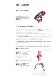
PUMPING UNITSGENERAL SPECIFICATIONSSCOPE OF SUPPLYThe <strong>FCE</strong> scope of supply focuses on Medium and HighPressure pumping units required in the Oil & Gas andIndustrial sectors.Thanks to its expertise, <strong>FCE</strong> provides pumping units toclient specifications. The packaging can be designed formobile services or fixed installation and suitable for variousoperating and environmental conditions.<strong>FCE</strong> units are mainly packaged with positive displacementpumps (reciprocating and progressive cavity pumps). Gearpumps or even centrifugal pumps can also be unitised.7MARKETS SERVED- Oil & Gas (Largest market).- Horizontal Drilling / Core Drilling.- Sewer Cleaning / Industrial Jetting.- Agriculture Spraying.- Reverse Osmosis.- General Industrial.OIL & GAS APPLICATIONSThere are various applications where an <strong>FCE</strong> pump unitcan be used such as:- Pipeline transfer(crude oil, condensate, kerosene, water, etc.).- Salt water disposal.- Waste water injection.- Methanol injection.- Glycol circulation into dehydration units.- Amine circulation into sweetening units.- Hydraulic oil circulation into BOP control units.- Lean oil circulation into LNG recovery absorbers.- Slop oil recycling.- Pipeline and well pressure test.- Pipeline and well cleaning(water and additives).- Brine injection (well killing).- Drilling Mud circulation.- Welltesting(crude oil transfer, chemical injection).- Etc.
PUMPING UNITSGENERAL SPECIFICATIONS8PACKAGING DESIGN CRITERIA<strong>FCE</strong> can provide pumping units per client specifications.However it is essential to specify several parameters:Process Conditions:- Required flow rates (Min. & Max.).- Required discharge pressure (Min. & Max.).- Available suction pressure.- Fluid characteristics and temperature.Environmental Conditions:- Climate.- Environmental regulations.- Classified area (explosion risks with flammable fluid).Operating conditions:- Type and frequency of operations.- Fixed or mobile service.- Available or supplied power.- Operating modes (ergonomic, maintenance, etc.).- Lifting modes and available lifting devices.- External connections (process, power, ground, etc.).Applicable norms:- International standards.- Client and project specifications.Scope of supply:- Equipment (safety devices, prime movers, instruments,miscellaneous options, spare parts, etc.).- Required test & inspection levels.- Required documentation.- Site commissioning, start-up assistance, training.- Extended guarantee.- Contract Incoterm (EXW, FOB, CFR, etc.).- Packing and shipment conditions.<strong>FCE</strong> EXPERTISEAs a warranty, <strong>FCE</strong> fully controls the design, fabricationprocess and product traceability of its pumping units.Each pumping unit is fully tested prior to shipment includingsafety device function test and recorded performancetest.Each pumping unit is serialised and fully documentedincluding a customised operating & maintenance manualand a quality book c/w all certificates.Site commissioning, training and start-up assistance by an<strong>FCE</strong> engineer are recommended.HOW TO MAKE A CHOICEReciprocating Pumps:Reciprocating pumps are used when it is impracticalor impossible to use a centrifugal pump. Application ismedium and high pressure.Properly equipped, these pumps are suitable for corrosive,abrasive, viscous, flammable & extremely hot or coldfluids.Advantages:- Capable of extremely high pressure up to 10000 PSI.- High mechanical efficiency (85-90%).- Flow capacity proportional to pump speed.- Simple field maintenance procedure.Disadvantages:- Requires a pressure safety device.- Higher NPSHr (may require a booster pump).- Pulsating flow creates vibrations.- Minor leakage is part of normal operation.Progressive Cavity Pumps:These pumps are suitable for abrasive, corrosive, viscous,flammable and even multiphase fluids.Advantages:- Low NPSHr.- Few pulsations.- Bi-directional.Disadvantages:- Limited discharge pressure.- Overall efficiency is affected by the pump speed.- Horizontal lenght can make installation problematic.Gear Pumps:These pumps are suitable for corrosive and viscous fluids.Advantages:- Low NPSHr.- Few pulsations.- Compact.Disadvantages:- Discharge pressure and flow capacity limits.- Not suitable for water and non lubricating fluids.Centrifugal Pumps:Centrifugal pumps are less costly and the more commonlyused. These pumps are suitable for various fluids, evencontaining solid particles.Advantages:- Low NPSHr.- Discharge pressure is automatically adjusteddepending on the flow rate.Disadvantages:- Limited discharge pressure.- Poor efficiency.- Not really suitable for viscous fluids.
PUMPING UNITSEXAMPLESINDUSTRIAL APPLICATIONS(Bare pump supply only)OIL & GAS APPLICATIONS(Fixed pumping unit supply)9Bare pumps for several applicationsCrude Oil Transfer into pipelineReciprocating pump & Centrifugal booster pump unit32 m 3 /h x 76 bars (4800 bbl/d x 1100 PSI)Zone-2 90 kW electric prime moverSewer CleaningCrude Oil Transfer into pipelineReciprocating pump unit (2 x 100% capacity)33 m 3 /h x 70 bars (5000 bbl/d x 1000 PSI)Zone-2 90 kW electric prime moverLight Duty Drilling(water well and civil works)Glycol Injection into gas pipelineReciprocating pump unit4.5 m 3 /h x 150 bars (670 bbl/d x 2170 PSI)Zone-2 37 kW electric prime mover
PUMPING UNITSEXAMPLESOIL & GAS APPLICATIONS(Mobile pumping unit supply)OIL & GAS APPLICATIONS(Mobile pumping unit supply)10Crude Oil Transfer into pipelineReciprocating pump & Centrifugal booster pump unit3800 bbl/d x 600 PSINon-Zoned 90 hp diesel engine prime moverMulti Service Mobile Pumping UnitReciprocating pump & Centrifugal booster pump unitHydraulic transmission2500 bbl/d x 1500 PSI or 600 bbl/d x 3000 PSIZone 2 107 hp or 85 hp diesel engine prime moverCrude Oil Transfer into pipelineReciprocating pump & Centrifugal booster pump unit2100 bbl/d x 5000 PSI up to 17300 bbl/d x 1500 PSINon-Zoned 440 hp diesel engine prime moverMulti Service Mobile Pumping UnitReciprocating pump & Centrifugal booster pump unitHydraulic transmission - 630 bbl/d x 3000 PSINon-Zoned 85 hp diesel engine prime moverAcidized Water Well Cleaning Unit3-pack light reciprocating pump & booster pump unit1600 bbl/d x 2000 PSIZone-2 85 hp diesel engine prime moverMulti Service Mobile Pumping UnitReciprocating pump & Centrifugal booster pump unitHydraulic transmission4500 bbl/d x 850 PSINon-Zoned 115 hp diesel engine prime mover
PUMPING UNITSQUESTIONNAIREQUESTIONNAIRERECIPROCATING PUMPSales manPhone No.Faxe-mail11123CompanyAddressPost codeCityDateCountry4567PhoneContactRequest No.Service:FaxContinuous (>8h/day)Web sitee-mailExpected due dateIntermittent (
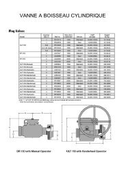
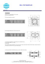
WELL SERVICE MANIFOLDSWELLTEST CHOKE MANIFOLDS12DESCRIPTIONThe Choke Manifold is used to control the well flow ratethrough a calibrated choke bean or adjustable choke.It also reduces the pressure before the flow enters theprocessing equipment. Dual flow paths allow fast chokechanges without flow interruption.The basic features include 4 API gate valves (5 with by-passline) and ½” ports for fluid sampling and well flow monitoring.Both rectangular and diamond shapes are available.Unionised plug valve models for both standard and sour gasservice are also available in 2” nominal size (1” max orifice)and 3” nominal size (2” max orifice).Each manifold is skid mounted with 4 lift points and 2 forkliftpockets.PROCESS & DESIGN DATA- API6A and NACE MR01-75 for sour gas service.- Nominal line size................ : 3” (with 2” max orifice).- Standard rating................. : 5000 / 10000 / 15000 PSI.- Temperature rating........... : -29°C to 121°C.- Inspection level per API.... : PSL2.5-Valve 3” rectangular choke manifoldOPTIONS- 2” and 4” nominal line size on customer request.- Wide variety of chokes.- Low temperature service (up to -40°C).- High temperature service (up to +190°C).- Specific inspection level on customer request(PSL3, PED certification & CE marking, etc.).- DNV 2.7.3 or 2.7.1 certified skid.Specific layouts such as vertical manifolds and otherintegrated functions can be supplied on request.WEIGHTS & DIMENSIONSRectangular type CM with API 6A gate valves - Model RGVSize & Rating 3 1/8 ” 5000 psi 3 1/16 ” 10000 psi 3 1/16 ” 15000 psiLength in mm 2200 2500 2500Width in mm 1900 2000 2000Height in mm 1100 1100 1200Weight in kg 2550 3000 42004-Valve 3” diamond choke manifoldDiamond type CM with API 6A gate valves - Model DGVSize & Rating 3 1/8 ” 5000 psi 3 1/16 ” 10000 psi 3 1/16 ” 15000 psiLength in mm 1900 2100 2100Width in mm 1900 2100 2100Height in mm 1000 1100 1200Weight in kg 1800 2500 3400Rectangular type CM with plug valves - Model RPVSize & Rating 2” 10000 psi 3” 10000 psiLength in mm 1650 1750Width in mm 1400 1500Height in mm 600 600Weight in kg 360 6854-Valve 2” rectangular choke manifold with plug valves
WELL SERVICE MANIFOLDSWELLTEST DIVERTER MANIFOLDSDESCRIPTIONDiverter manifolds are generally used downstream ofseparators, surge and gauge tanks.Oil diverters consist of 5 ball valves, 2 inlets and 3 outlets.Gas diverters consist of 2 ball valves, 1 inlet and 2 outlets.Each manifold is skid mounted with 4 lift points and 2 forkliftpockets.PROCESS & DESIGN DATA- ANSI B31.3 / NACE MR01- 75 for sour gas service.- Standard nominal size.................. : 3”.- Pressure rating............................... : 1440 PSI at 38 °C.- Temperature rating: ..................... : -29 °C to 121 °C.OPTIONS- Other sizes on request (2”, 4”, 6” etc.).- Other pressure ratings on request.- Other configurations and layouts on request.- Double block and bleed valves.- Additional check valve.- Low temperature service (up to -40 °C).- High temperature service (up to +190 °C).- PED certification (CE marking).- DNV 2.7.3 or 2.7.1 certified skid.WEIGHTS & DIMENSIONS2-Valve x 3” gas diverter manifold with check valve5-Valve x 3” oil diverter manifold with check valveDouble-block & bleed x 6” gas diverter manifold13Model Length in mm Width in mm Height in mm Weight in kg2-valve 3’’ gas manifold 1500 500 550 4502-valve 4’’ gas manifold 1900 600 560 5505-valve 3’’ oil manifold 2150 800 550 6505-valve 4’’ oil manifold 2765 900 560 1240WELL SERVICE MANIFOLDSDRILLING CHOKE MANIFOLDSDESCRIPTIONThe Drilling Choke Manifold is used to control the drillingfluid from the well whilst drilling. Each manifold is built tothe customers required layout and generally allows flowthrough 2 or 3 adjustable Chokes. These are all equippedwith heavy duty and wear resistant trims operated from aremote hydraulic control panel.OPTIONS- Low temperature service (up to -40 °C).- High temperature service (up to +190 °C).- Specific inspection level on customer request(PSL3, PED certification & CE marking, etc.).- DNV 2.7.3 or 2.7.1 certified skid.The basic features include API gate valves and necessaryports with instruments for flow monitoring.PROCESS & DESIGN DATAAPI6A and NACE MR01-75 for sour gas service.Nominal line size................... : 3” & 4”.Standard rating.................... : 5000 / 10000 / 15000 PSI.Temperature rating.............. : -29 °C to 121 °C.Inspection level per API....... : PSL2.4” 1/16 5000 PSI Drilling Choke Manifoldwith solid buffer chamber
WELL SERVICE MANIFOLDSMISCELLANEOUS MANIFOLDS14Configurations can be built to customer requirements andaccording to specific applications such as:- Welltest vertical choke manifolds with ESDV and dataheader.- Welltest by-pass manifolds.- Welltest BS&W manifolds.- Drilling Stand pipe manifolds.- Frac Flowback manifolds.- Gravel Pack / Squeeze manifolds.- Etc.SOLIDS REMOVAL EQUIPMENTFILTER PUPSDESCRIPTIONThe filter pup consists of an inline removable screen andouter ”casing”, allowing solid particles removal from the welleffluent with fluid flow from outside the screen to the inside.The filter pup is supplied with its adaptors to match the line size.Because of its limited retention volume, the filter pup isgenerally used for temporary operations. However, skidmounted combinations including a number of filters andsuitable inlet and outlet manifolding can be supplied atclient request.PROCESS & DESIGN DATA- ANSI B31.3, Standard service.- Pressure rating.................. : 5000 / 10000 PSI.- Temperature rating.......... : -29°C to 121°C.- Filtration cut-out............... : 300 and 800 microns.3” Inline filter pup for 2” line sizeWEIGHTS & DIMENSIONS (for skid units and 3” nominal flow line)Line Size 2” 3”Filter body size 3” 4”Liquid flow capacity20 m3/h 42 m3/h3100 bbl/d 6000 bbl/dConnections 2” fig.1502 3” fig.1502OPTIONS- ”In” to ”Out” flow direction.- Other sizes and pressure ratings on request.- Other filtration cut-outs on request (50 to 1000 microns).- Low temperature service (up to -40°C).- High temperature service (up to +190°C).- NACE MR01-75 for sour gas service.- Skid mounted combinations at customer request.Solids removal skid unitNo. of 4” filter pups (vertically) 2 4 6 8Length in mm 1600 1600 2300 3200Width in mm 1800 2400 2400 2400Height in mm 2500 2500 2500 2500Weight in kg 2500 3500 5000 7000
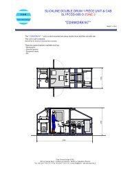
SOLIDS REMOVAL EQUIPMENT2-STAGE DUAL POT SAND FILTERSDESCRIPTIONPrinciple of operationThe Dual Pot Sand Filter is designed to remove solid particlesfrom well effluent. Located after the flowhead, it protectsdownstream equipment against erosion.The 2-SF (2 - Stage Filtration) dual pot sand filter offers manyadvantages when compared to conventional models:The first stage filtration is achieved by centrifugal separationwhilst the second stage filtration employs an advancedremovable screen to perform a mechanical cut-out. Thevessels are fitted with a removable wear sleeve and thenecessary nozzles for flushing with water.As the fluid flows from outside to inside the screen, the flowarea is not obstructed by the sand accumulation, providinga longer operating time compared to competitors.ConfigurationThe Unit consists of:- 2 filters pots.- 5-Valve 3” 1/16 process manifold (10K gate valves).- 2-Valve 2” 1/16 drain manifold (10K gate valves).- Dump line c/w 2” manually operated adjustable choke.- One piece skid c/w platforms, ladder and handrails.- 2 x 4 ISO corner blocks (on horizontal skid only).- 2 forklift pockets and 4 lift lugs.The horizontal layout with all connections on one side makesrig-up and site erection easier. It can be easily installed ontoa trailer which is ideal for onshore use.The standard 3” I.D. manifold provides less pressuredrop across the unit compared to most designs offeringconstruction from 3” nominal pipe.A vertical layout can be also offered when limited footprintis a major issue (i.e. some offshore applications). In case flowdirection may be “in” to “out”.PROCESS & DESIGN DATAAPI 6A / ASME / ANSI B31-3 / NACE MR01-75.Gas capacity.............................. : 35 MMSCF/D.Liquid capacity........................... : 5000 BBL/D (@ 200 µ).Design pressure........................... : 10 000 PSI.Design temperature................... : -29°C to 121°C.Std filter cut-out.......................... : 100, 200 or 400 µm.Std Max Diff. Pressure................. : 1350 PSI.Inspection level per API.............. : PSL2.Inlet & Outlet connections......... : 3” figure 1502.Drain outlet connection............ : 2” figure 1502.OPTIONS- Double block and bleed valve process manifold(9 valves).- 4” figure 1502 unions.- 4” 1/16 process manifold.- Low temperature service (up to -40°C).- High temperature service (up to +190°C).- Specific inspection level on customer request(PSL3, PED certification & CE marking, etc.).- DNV 2.7.3 or 2.7.1 certified skid.WEIGHTS & DIMENSIONS (With 3” 1/16 process manifold)Model Horizontal VerticalLength in mm 6058 C.F.Width in mm 2438 C.F.Height in mm 2700 C.F.Weight in kg 8500 C.F.15Horizontal sand filter (9 valve manifold shown)
WELLTESTING EQUIPMENT FLOWHEADS16DESCRIPTIONThe flowhead is used as a temporary wellhead on a drillingrig. <strong>FCE</strong> offers a compact light weight unitized flowheadfitted with:- 2 1/16 ” kill wing gate valve & a 2” Fig.1502F connection.- 3 1/16 ” flow wing gate valve & a 3” Fig.1502M connection.- 3” upper and lower Kelly valves.- 400 000 lbs Swivel allowing the test string to rotate.- 4 ½ ” IF bottom sub connection c/w test cap.- 5¾” - 4 Otis ACME box lift sub top connection c/w pin andcollar test cap.The flowhead is supplied with it’s own lift sub and can beunitised with it’s own transport skid.The flow wing gate valve is fitted with a hydraulic actuatorand can be used as an ESD valve.OPTIONS- 250 000 lbs Swivel.- Low temperature service (up to -40°C).- High temperature service (up to +190°C).- Other top and bottom connections on request.- “Stiff” Joint- Check valve on kill wing.- Specific inspection level on customer request.(PSL3, PED certification & CE marking, etc.).- DNV 2.7.3 or 2.7.1 certified skid.PROCESS & DESIGN DATAAPI 6A / NACE MR 01-75 for sour gasDesign pressure ......................................... : 10 000 PSI.Design temperature ................................. : -29°C to 121°C.Wing valve hyd. operating pressure ....... : 6000 PSI max.Inspection level ......................................... : PSL2.WEIGHTS & DIMENSIONS (with transport skid)Length in mm 5000Width in mm 1500Height in mm 1600Weight in kg 2500WELLTESTING EQUIPMENTESDV’S & CONTROL SYSTEMSDESCRIPTIONEmergency ShutDown Valves (ESDV) for well testingapplications are generally reverse acting gate valvesequipped with a hydraulic linear actuator (occasionallypneumatic) and complete with the required x-overs. Inoffshore applications this valve may be incorporated intoa flowhead, but for land use, it is normally skid mountedand installed close to the wellhead. Actuators are fail close,usually single acting with hydraulic pressure to open andspring assist to close upon the loss of hydraulic pressure.The ESD Panel, in its more basic form, consists of a smallhydraulic oil tank, an air driven hydraulic pump providingopening pressure via a hose to the ESDV and a hydrauliccircuit to permit ”push button” ESDV closure.The panel will receive its ”process” signal from upstream highor low pressure switches (or pilots) or from additional inputs.PROCESS & DESIGN DATAAPI6A and NACE MR01-75 for sour gas service.Nominal line size .................... : 3”Standard rating ..................... : 5000 / 10000 / 15000 PSI.Temperature rating ............... : -29°C to 121°C.Inspection level per API ........ : PSL2.WEIGHTS & DIMENSIONSLength in mm 1200Width in mm 500Height in mm 1660Weight in kg 610OPTIONS- 2” or 4” ESD valve size.- Hand pump.- Additional pumps.- Additional process inputs (fusible plug/fire detection,gas alarms, etc.) up to a Full Blown ”Process Panel”.- Specific inspection level on customer request.(PSL3, PED certification & CE marking, etc.).- DNV 2.7.3 or 2.7.1 certified skid.3 1/8 ” x 5000 PSI ESD Valve c/wportable control panel and remote ESD stations
WELLTESTING EQUIPMENTTEST SEPARATORSDESCRIPTIONTest separators are 3-phase (gas, oil and water) vessels fullyequipped with pressure and level controls, liquid flowmeters,gas flow recorder, gauges and shrinkage tester.<strong>FCE</strong> offers the most commonly used sizes:- Horizontal 1440 PSI - 42” x 15’.- Horizontal 1440 PSI - 42” x 10’.- Horizontal 600 PSI - 42” x 10’.Other sizes and pressure ratings, either horizontal or verticaldesign, can be supplied to client request.PROCESS & DESIGN DATA- API 12J / ASME VIII div.1 / ANSI B31-3.NACE MR01-75 for sour gas.- Design temperature....... : -29°C to 100°C.Size & Rating600 PSI42”x10’1440 PSI42”x10’1440 PSI42”x15’Design Press. 600 psi 1345 psi 1345 psiGas capacity 33.2 MMscf/d 44.8 MMscf/d 56.0 MMscf/dOil capacity 9430 bbl/d 8870 bbl/d 13210 bbl/dWater capacity 2650 bbl/d 2060 bbl/d 3080 bbl/dTotal liquid cap. 12080 bbl/d 10930 bbl/d 16290 bbl/dWEIGHTS & DIMENSIONSSize & Rating600 PSI 1440 PSI 1440 PSI42”x10’ 42”x10’ 42”x15’Length in mm 6058 6058 7530Width in mm 2438 2438 2438Height in mm 2590 2590 2590Weight in kg 11200 14200 16900Note: dimensions are given for skid design with ISO blocks.OPTIONS- Low temperature to -40°C.- LSH / LSL nozzles / alarms for EPF purposes.- Various liquid flowmeter types & brands.- Various valves and component brands.- Various adders on request (Check valves, instruments, etc.).- Additional 2’’ or 3’’ gas measuring line.- DNV 2.7.3 or 2.7.1 certified skid.- ASME U-stamp or PED certification (CE Marking).- Data Acquisition System and sensors.17Note 1:The design pressure is given for Max temp. of 100°C (212°F).1440 PSI design pressure is limited to 38°C (100°F) by theflange rating of 600#RF on those separators.Note 2:The flow rates given are nominal capacities for:- 1 minute retention time for liquids.- Oil/Gas interface at vessel centreline.- Water/Oil interface at LC nozzle elevation.- Gas S.G. of 0.7.- Gas temperature of 54°C.Flow capacities will vary depending on level adjustmentand process conditions.
WELLTESTING EQUIPMENTINDIRECT HEATERS18DESCRIPTIONIndirect heaters help prevent wax formation in downstreamequipment and also hydrate formation at choke valves.Where required it can also assist in breaking down anyemulsions by reducing oil viscosity.<strong>FCE</strong> offers the following standard heaters:- 2.0 MMBTU/h Natural Draft Indirect Heater.- 0.5 to 2.0 MMBTU/h Forced Draft Indirect Heater.- 0.8 to 2.8 MMBTU/h Forced Draft Indirect Heater.The Natural Draft version is fully pneumatically controlled whilstthe Forced Draft versions are equipped with an electricallypowered burner.PROCESS & DESIGN DATA- API 12K / ANSI B31-3 / NACE MR01-75 for sour gas.- Design temperature.... : -29°C to 100°C.- Standard 2-stage coil.. : 3” 5000 PSI x 3” 2500 PSI.WEIGHTS & DIMENSIONSOPTIONSSize & Rating2.0 MMbtu/h ND- Other coil pressure ratings and sizes.- Other manifold pressure ratings.- Standard service.- DNV 2.7.3 or 2.7.1 certified skid.- PED certification (CE marking).2.0 MMbtu/h FD2.8 MMbtu/h FDLength in mm 6058 6058 7500Width in mm 2438 2438 2438Height in mm 2800 2800 2800Weight in kg 11000 12000 14000WELLTESTING EQUIPMENTSURGE TANKSDESCRIPTIONSurge tank is generally used in the presence of H2S and sitedbetween the separator and burners. It allows batch flowregulation, degassing at low pressure and can also be usedas a pressurised gauge tank.The vessel can be fitted with LSL and LSH providing apneumatic signal for an alarm horn or external control.<strong>FCE</strong> offers two models:- 100 bbl single compartment.- 2 x 50 bbl dual compartment.OPTIONS- Lower capacity on request.- LSHH / LSLL nozzles / alarms for EPF purpose.- Low temperature service to -40°C.- Various valves and component brands.- Various adders on request (Check valves, instruments, etc.).- Additional gas measuring run (4” standard or other sizes).- DNV 2.7.3 or 2.7.1 certified skid.- ASME U-stamp or PED certification (CE marking).PROCESS & DESIGN DATA- ASME VIII div.1 / ANSI B31-3 / NACE MR01-75.- Design temperature......... : -29°C to 100°C.- Standard pressure............ : 50, 100 or 150 PSI.- Net batch capacity......... : 100 bbl or 2 x 50 bbl.WEIGHTS & DIMENSIONS(For 150 PSI version and horizontal position)Model 2 x 50 bbl 100 bblLength in mm 7450 7450Width in mm 2500 2500Height in mm 2750 2750Weight in kg 14450 14050
WELLTESTING EQUIPMENTGAUGE TANKSDESCRIPTIONThe Gauge tank is an atmospheric tank, used for metercalibration. The tank is fitted with inlet/outlet/drainbutterfly valves, gauge hatches, a flame arrestor on thevent line and graduated sight glasses.Gauge tanks are of dual compartment construction withavailable capacities of 2 x 50 bbl or 2 x 100 bbl.19WEIGHTS & DIMENSIONModel 2 x 50 bbl 2 x 100 bblLength in mm 3920 6720Width in mm 2410 2410Height in mm 3324 3324Weight in kg 4300 6800WELLTESTING EQUIPMENTMISCELLANEOUS TANKSMiscellaneous tanks for different applications can besupplied to customer requirements:- Skid mounted temporary storage tanks.- Utility tanks (fuel, water, etc.).- Indirect heater fuel tanks.- Sand recovery tanks (for sand filter unit).- Etc.1200 L fuel tank for indirect heater
WELLTESTING EQUIPMENTTRANSFER PUMPS20DESCRIPTIONTransfer pump allows the transfer of oil from a tank to aburner or to an existing flowline and even to a tank trailer.<strong>FCE</strong> offers a basic 4000 bbl/d x 300 PSI progressive cavitypump unit that covers the majority of the applications usedand is able to transfer a wide variety of fluids. Each skid unitis fitted with 4 lifting points and 2 forklift pockets.Available versions are:SD-S: non-zoned diesel engine driven.SD-Z: zone-2 diesel engine driven.SE-Z: zone-2 electric motor driven (50 Hz-240 Vac).Other solutions with centrifugal pumps for high flowrateand non viscous fluids or gear pumps for viscous and selflubricating fluids can also be designed to client request.Reciprocating pumps for high/medium discharge pressurecan also be supplied (see pump units - page 8).PROCESS & DESIGN DATAANSI B31-3 / API.H2S service up to 200 ppm.Design temperature....... : 0°C to 80°C.Nominal Capacity.......... : 4000 bbl/d x 300 PSI.OPTIONS- Low temperature service -40°C.- Higher temperature on request.- H2S service up to and above 500 ppm.- 60 Hz power supply (for SE-Z only).- DNV 2.7.3 or 2.7.1certified skid.- NACE MR01-75 for sour gas.- PED certification (CE Marking).WEIGHTS & DIMENSIONSModel SD-S SD-Z SE-ZLength in mm 3500 3500 3500Width in mm 1000 1000 1000Height in mm 1760 1760 1560Weight in kg 2100 2350 2000Electric motor driven Transfer Pump (SE-Z model)Diesel engine driven Transfer Pump (SD-S model)
WELLTESTING EQUIPMENTCABS & ANALYSIS DEVICESCABSOperator cabs are available as non-zoned safe area based on standard ISOcontainers 10’, 20’ or 40’ and equipped as laboratory, workshop, office, utilitieshouse (c/w generator and air compressor) or a combined arrangement.Cabs are built to customer requirements including insulation, furniture, electrical& pneumatic systems, air conditioning, etc. A specific structure, other than acontainer base, can also be designed / supplied at client request.21FLUID ANALYSIS DEVICESFluid analysis devices are normally supplied loose in orderto allow fluid sampling and simple analysis on site of varioushydrocarbon criteria:Pressure- DWT (Dead Weight Tester) for calibration purposes.- Pressure Recorders (one-pen or multi-pen).Oil Gravity- A range of hydrometers with sample cylinders.- Electric powered gravitometer.Gas gravity- Ranarex electric driven gravitometer.BSW (Basic Sediment & Water)- Hand driven centrifuge c/w set of cone glasses.- Electric powered centrifuge (as an alternative).PH analysis- A range of PH papers.- Electric driven instruments for manual sampling.Salinity kit (refractometer)Hand held spectrometer.Gas detectionMultigas detector with bellows pump to determine H2Sand CO2 presence c/w a range of sample tubes to covermain gas constituents.ViscosityElectric driven viscometer.SamplingEquipment is required to enable full PVT / other analysis tobe undertaken in a laboratory.<strong>FCE</strong> can thus provide oil sample bottles, gas samplebottles and the required transfer bench.Electric centrifugeHand-held refractometerDead Weight TesterGas gravitometer
WELLTESTING EQUIPMENTDATA ACQUISITION SYSTEMS22The Data Acquisition Systems and sensors integrated by <strong>FCE</strong>are selected from recognized partners & suppliers.The systems consist of:- Various sensors (PT, DPT, TT, FQT).- Sensor cables & terminal junction block(s).- Multicore cable reel(s) from terminal block(s) to logger.- Data logger to interface with client computer(s).- Windows® based Software & dongle.- Training directly supported by the system designer.The software is particularly designed for well serviceoperations. It allows real time reading, input for flow andpressure variables, and tailored report formats can begenerated during the job.Major partner: FARDUX (Wellwise Group, UK).Main characteristics & options- Intrinsically safe system with safety barriers.- Basic 12-channel logger for normal welltesting.- Alternate 24-channel logger for EPF.WELLTESTING EQUIPMENTPACKAGED SOLUTIONSMobile Testing Units (MTU):Where reduced logistics are a concern, Mobile Testing Unitsoffer efficient solutions providing fast movement and rig-up /rig-down operations with a minimum number of vehicles.Trailer mounted MTU (and even truck mounted units) aredesigned to suit road conditions in respect to admissibleaxle loads and area of operation. Safe areas, easy, safeaccess to equipment and efficient layout storage arealways considered in the design.Several combined options of MTU can be studied in regardto field conditions and operation philosophies including:Extended Welltest:Extended Welltest operations may require specificdesign and sizing of process equipment as well asadditional controls and back-up facilities in order tomeet expected performance and the required safetylevel.<strong>FCE</strong> designs and provides complete or partial packagedsolutions to suit customer requirements including basicand detailed engineering (HAZOP, PFD, PID, etc.) asrequired.- Processing equipment.- Fluid storage and transfer.- Interconnecting elements.- Cab, workshop, utilities & accommodation.- Data Acquisition System.
PRODUCTION EQUIPMENTSEPARATIONBased on welltesting separator expertise, <strong>FCE</strong> has thecapacity to design and provide 2-phase and 3-phaseproduction separators on a case by case basis.The scope of supply can be extended to small packageswith onsite start-up assistance.23PRODUCTION EQUIPMENTWATER FILTRATIONDESCRIPTIONWater injection into the well is often required in oil and gasfields in order to optimise the reservoir pressure capacityand to reduce formation damage.The water will be filtered prior to injection.<strong>FCE</strong> Filtration Units are specifically designed for High Pressureand Low Filtration Cut-outs down to 2 µ.The unit consists of 2 pots in parallel allowing fast switchoverand cartridge changeout whilst flowing, and is equippedwith a 5-valve compact manifold, a centralised controlpanel with DP gauge and 3” unionised connections.Each pot is internally protected with a erosion and corrosionresistant fibber glass lining.WEIGHTS & DIMENSIONSModel DFU-01 DFU-02Pressure rating 3000 PSI 5000 PSILength in mm 3000 3000Width in mm 1900 1900Height in mm 2650 2650Weight in kg 5000 6000PROCESS & DESIGN DATA- ASME VIII Div.1 guidance, ANSI B31-3.- Design Pressure............. : 3000 PSI / 5000 PSI.- Design Temperature..... : -29°C to 121°C.- Liquid flow capacity..... : 20000 bbl/d.- Filtration cut-out............ : from 2 to 20 µ.OPTIONS- Other filtration cut-outs on request.- Other flow capacities on request.- DNV 2.7.3 or 2.7.1 certified skid.
PRODUCTION EQUIPMENTMANIFOLDING24On a case by case basis, <strong>FCE</strong> can design and supply specificmanifolds and skid units for various applications to customerrequirements related to fluid control, metering and analysis.BS&W measuring skidGas metering and pressure control skidMultiphase metering skid (meter not shown)Liquid blending & metering skidProduction compact manifold
+33 (0)4 77 48 13 13+33 (0)4 77 33 01 30fce@fce.fr786 rue George Sand - ZI Molina la Chazotte42350 La Talaudière FRANCEFluid Control AlgérieZone d’Activité N°3 Lot 17BP 50630500 Hassi MessaoudAlgérie+213 (0)29 73 73 35fca@fce.frCréation graphique : District 360 - Impression i.d.0 - 04 77 52 96 09certifié imprim’vert, imprimé sur papier couché moderne 300g recyclableLabel PEFC (certification de gestion forestière durable) - 02/2010