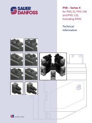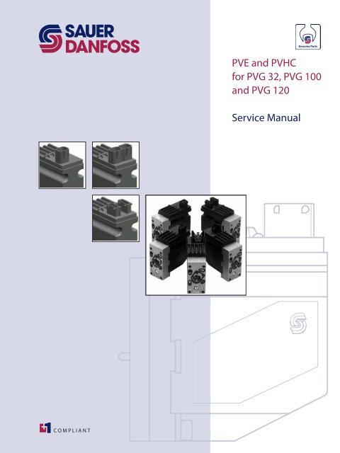
PVE and PVHC for PVG 32, PVG 100 and PVG 120 ... - Sauer-Danfoss
PVE and PVHC for PVG 32, PVG 100 and PVG 120 ... - Sauer-Danfoss
PVE and PVHC for PVG 32, PVG 100 and PVG 120 ... - Sauer-Danfoss

Create successful ePaper yourself
Turn your PDF publications into a flip-book with our unique Google optimized e-Paper software.
<strong>PVE</strong> <strong>and</strong> <strong>PVHC</strong><br />
<strong>for</strong> <strong>PVG</strong> <strong>32</strong>, <strong>PVG</strong> <strong>100</strong><br />
<strong>and</strong> <strong>PVG</strong> <strong>120</strong><br />
Service Manual
2 L1223449 • Rev AA • May 2012<br />
<strong>PVE</strong> <strong>and</strong> <strong>PVHC</strong> <strong>for</strong> <strong>PVG</strong> <strong>32</strong>, <strong>PVG</strong> <strong>100</strong> <strong>and</strong> <strong>PVG</strong> <strong>120</strong><br />
Service Manual<br />
Revisions, Contents<br />
Revision History Table of Revisions<br />
Date Page Changed Rev<br />
May 2012 - New edition AA<br />
Abbreviations Chart<br />
Warnings<br />
General In<strong>for</strong>mation<br />
Exchanging <strong>PVE</strong> or <strong>PVHC</strong><br />
List of abbreviations ...................................................................................................................................... 3<br />
<strong>Sauer</strong>-<strong>Danfoss</strong> literature reference .......................................................................................................... 4<br />
Product Warnings ........................................................................................................................................... 5<br />
Introduction ..................................................................................................................................................... 7<br />
General Instructions ...................................................................................................................................... 7<br />
Safety Precautions.......................................................................................................................................... 8<br />
Overview ........................................................................................................................................................... 9<br />
Trouble Shooting ..........................................................................................................................................10<br />
Hydraulic variants: <strong>PVE</strong>A ......................................................................................................................11<br />
<strong>PVE</strong> with ramp ..........................................................................................................................................11<br />
Be<strong>for</strong>e replacing or dismounting a <strong>PVE</strong> or <strong>PVHC</strong> ..............................................................................12<br />
Dismounting of a <strong>PVE</strong> or <strong>PVHC</strong> ................................................................................................................13<br />
Mounting of Replacement ........................................................................................................................13<br />
Test <strong>and</strong> use of <strong>PVG</strong> <strong>and</strong> Actuator ..........................................................................................................14<br />
Returning Replaced Actuator <strong>for</strong> Customer Claims .........................................................................14<br />
Important Note <strong>for</strong> Digital Actuators ....................................................................................................14<br />
Parameter transfer .......................................................................................................................................14<br />
Be<strong>for</strong>e disconnecting the failing <strong>PVE</strong>D-CC from the system ...................................................14<br />
After mounting the new <strong>PVE</strong>D-CC on the <strong>PVG</strong> ...........................................................................15<br />
© 2012 <strong>Sauer</strong>-<strong>Danfoss</strong>. All rights reserved.<br />
<strong>Sauer</strong>-<strong>Danfoss</strong> accepts no responsibility <strong>for</strong> possible errors in catalogs, brochures <strong>and</strong> other printed material.<br />
<strong>Sauer</strong> -<strong>Danfoss</strong> reserves the right to alter its products without prior notice. This also applies to products already<br />
ordered provided that such alterations can be made without affecting agreed specifications. All trademarks<br />
in this material are properties of their respective owners. <strong>Sauer</strong>-<strong>Danfoss</strong>, the <strong>Sauer</strong>-<strong>Danfoss</strong> logotype, the<br />
<strong>Sauer</strong>-<strong>Danfoss</strong> S-icon, PLUS+1, What really matters is inside® <strong>and</strong> Know-How in Motion are trademarks of the<br />
<strong>Sauer</strong>-<strong>Danfoss</strong> Group.<br />
Front cover illustrations:V310299, V310300, V310292, F300704, drawing 157-506.
<strong>PVE</strong> <strong>and</strong> <strong>PVHC</strong> <strong>for</strong> <strong>PVG</strong> <strong>32</strong>, <strong>PVG</strong> <strong>100</strong> <strong>and</strong> <strong>PVG</strong> <strong>120</strong><br />
Service Manual<br />
Abbreviations Chart<br />
List of Abbreviations Abbreviation Description<br />
ASIC Application Specific Integrated Circuit - the part of the <strong>PVE</strong> where spool position is<br />
controled to follow setpoint<br />
ATEX Certificated <strong>for</strong> use in flammable environment<br />
AVC Auxillery Valve Com<strong>and</strong> - ISOBUS/J1939 st<strong>and</strong>ard signal <strong>for</strong> valve control<br />
AVCTO Auxillery Valve Com<strong>and</strong> Time Out - Fault monitoring setting<br />
AVEF Auxillery Valve Estimated Flow - ISOBUS/J1939 st<strong>and</strong>ard signal <strong>for</strong> valve feedback<br />
CAN Controller Area Network - Communication method used by <strong>PVE</strong>D<br />
CLC Closed Loop Circuit<br />
CRC Cyclic Redundancy Check - Method <strong>for</strong> ensuring validity of data.<br />
-DI <strong>PVE</strong> with Direction Indication<br />
DM1 Diagnostic Message 1 - J1939 message in<strong>for</strong>ming about present fault<br />
DM2 Diagnostic Message 2 - J1939 message in<strong>for</strong>ming about fault history<br />
DM3 Diagnostic Message 3 - J1939 message clearing fault history<br />
DSM Device State Machine. Deterministic description of system process<br />
ECU Electronic Control Unit<br />
EH Electro Hydraulic<br />
-F <strong>PVE</strong> <strong>for</strong> Float spool. Two variants: 4 pin with float at 75%. 6 pin with separate float.<br />
FMEA Failure Mode Effect Analysis<br />
ISOBUS Communication st<strong>and</strong>ard <strong>for</strong> CAN<br />
J1939 Communication st<strong>and</strong>ard <strong>for</strong> CAN<br />
LED Light Emitting Diode<br />
LS Load Sensing<br />
LVDT Linear Variable Differential Transducer - Position sensor<br />
NC Normally Closed solenoid valve in <strong>PVE</strong><br />
NC-H Normally Closed st<strong>and</strong>ard solenoid valve - like in <strong>PVE</strong>H<br />
NC-S Normally Closed solenoid valve Super - like in <strong>PVE</strong>S<br />
NO Normally Open solenoid valve in <strong>PVE</strong><br />
PLC Programmable Logical Circuit<br />
PLUS+1 Trademark <strong>for</strong> <strong>Sauer</strong>-<strong>Danfoss</strong> controllers <strong>and</strong> programming tool<br />
POST Power On Self Test. Boot up evaluation <strong>for</strong> <strong>PVE</strong>D<br />
Pp Pilot Pressure. The oil gallery <strong>for</strong> <strong>PVE</strong> actuation<br />
PVB Proportional Valve Basic module - valve slice<br />
PVBS Proportional Valve Basic module Spool<br />
PVBZ Proportional Valve Basic module Zero leakage<br />
<strong>PVE</strong> Proportional Valve Electric actuator<br />
<strong>PVE</strong>A <strong>PVE</strong> variant with 2-6 % hysteresis<br />
<strong>PVE</strong>D <strong>PVE</strong> variant Digital controlled via CAN communication<br />
<strong>PVE</strong>H <strong>PVE</strong> variant with 4-9% hysteresis<br />
<strong>PVE</strong>M <strong>PVE</strong> variant with 25-35% hysteresis<br />
<strong>PVE</strong>O <strong>PVE</strong> variant with ON/OFF actuation<br />
<strong>PVE</strong>P <strong>PVE</strong> variant PWM controled<br />
<strong>PVE</strong>S <strong>PVE</strong> variant with 0-2% hysteresis<br />
<strong>PVE</strong>U <strong>PVE</strong> variant with U S 0-10V<br />
<strong>PVG</strong> Proportional multi-section Valve Group<br />
<strong>PVHC</strong> PV variant with Current controlled valve actuator<br />
PVM Proportional Valve Manual control with h<strong>and</strong>le<br />
PVP Proportional Valve Pump side module.Inlet<br />
PVS Proportional Valve end plate<br />
PVSK Proportional Valve end plate Crane. Inlet module with Spool Control<br />
L1223449 • Rev AA • May 2012<br />
3
List of Abbreviations<br />
4 L1223449 • Rev AA • May 2012<br />
<strong>PVE</strong> <strong>and</strong> <strong>PVHC</strong> <strong>for</strong> <strong>PVG</strong> <strong>32</strong>, <strong>PVG</strong> <strong>100</strong> <strong>and</strong> <strong>PVG</strong> <strong>120</strong><br />
Service Manual<br />
Abbreviations Chart<br />
Abbreviation Description<br />
(continued) PWM Pulse Width Modulation<br />
-R <strong>PVE</strong> with Ramp function<br />
S4 DJ Series 4 Digital J1939 service tool software <strong>for</strong> <strong>PVE</strong>D-CC<br />
SAE Society Automotive Engineering<br />
-SP <strong>PVE</strong> with Spool Position feedback<br />
uC Micro-Controller<br />
uCSM Micro-Controller State Machine<br />
UDC Power supply Direct Currentl; also called V <strong>for</strong> battery voltage<br />
bat<br />
US Steering voltage <strong>for</strong> the <strong>PVE</strong> control; also called VS <strong>Sauer</strong>-<strong>Danfoss</strong> Literature<br />
Reference<br />
<strong>Sauer</strong>-<strong>Danfoss</strong> literature reference <strong>for</strong> <strong>PVG</strong> <strong>and</strong> <strong>PVE</strong> products<br />
Title Type Order number<br />
<strong>PVG</strong> <strong>32</strong> Proportional Valve Groups Service Manual 11039167<br />
<strong>PVG</strong> <strong>100</strong> Proportional Valve Groups Service Manual 11048807<br />
<strong>PVG</strong> <strong>32</strong> Proportional Valve Groups Technical In<strong>for</strong>mation 520L0344<br />
<strong>PVG</strong> <strong>100</strong> Proportional Valve Groups Technical In<strong>for</strong>mation 520L0720<br />
<strong>PVG</strong> <strong>120</strong> Proportional Valve Groups Technical In<strong>for</strong>mation 520L0356<br />
<strong>PVE</strong> Series 4 <strong>for</strong> <strong>PVG</strong> <strong>32</strong>, <strong>PVG</strong> <strong>100</strong> <strong>and</strong> <strong>PVG</strong> <strong>120</strong> Technical In<strong>for</strong>mation 520L0553<br />
<strong>PVE</strong>D-CC Electro Hydraulic actuator Technical In<strong>for</strong>mation 520L0665<br />
<strong>PVE</strong>D-CX Electro Hydraulic actuator Technical In<strong>for</strong>mation 11070179<br />
<strong>PVG</strong> <strong>32</strong> Metric ports Technical In<strong>for</strong>mation 11051935
<strong>PVE</strong> <strong>and</strong> <strong>PVHC</strong> <strong>for</strong> <strong>PVG</strong> <strong>32</strong>, <strong>PVG</strong> <strong>100</strong> <strong>and</strong> <strong>PVG</strong> <strong>120</strong><br />
Service Manual<br />
Warnings<br />
Product Warnings �Warning<br />
All br<strong>and</strong>s <strong>and</strong> all types of directional control valves – including proportional valves<br />
– can fail <strong>and</strong> cause serious damage. It is there<strong>for</strong>e important to analyze all aspects of<br />
the application. Because the proportional valves are used in many different operation<br />
conditions <strong>and</strong> applications, the machine builder/ system integrator alone is responsible<br />
<strong>for</strong> making the final selection of the products – <strong>and</strong> assuring that all per<strong>for</strong>mance, safety<br />
<strong>and</strong> Warning requirements of the application are met.<br />
�Warning<br />
A <strong>PVG</strong> with <strong>PVE</strong> can only per<strong>for</strong>m according to description if conditions in the Technical<br />
In<strong>for</strong>mation are met.<br />
�Warning<br />
In particularly exposed applications, protection in the <strong>for</strong>m of a shield is recommended.<br />
�Warning<br />
When the <strong>PVE</strong> is in fault mode the quality of per<strong>for</strong>mance <strong>and</strong> validity of feedback is<br />
limited depending on the fault type.<br />
�Warning<br />
Error pins from more <strong>PVE</strong>s may not be connected. Inactive error pins are connected to<br />
ground <strong>and</strong> will disable any active signal.<br />
�Warning<br />
Error pins are signal pins <strong>and</strong> can only supply very limited power consumption.<br />
�Warning<br />
Deviation from recommended torque when mounting parts can harm per<strong>for</strong>mance <strong>and</strong><br />
module.<br />
�Warning<br />
Adjustment of the position transducer (LVDT) will influence calibration, <strong>and</strong> thereby also<br />
safety <strong>and</strong> per<strong>for</strong>mance.<br />
�Warning<br />
When replacing the <strong>PVE</strong>, the electrical <strong>and</strong> the hydraulic systems must be turned off <strong>and</strong><br />
the oil pressure released.<br />
L1223449 • Rev AA • May 2012<br />
5
Product Warnings<br />
(continued)<br />
6 L1223449 • Rev AA • May 2012<br />
<strong>PVE</strong> <strong>and</strong> <strong>PVHC</strong> <strong>for</strong> <strong>PVG</strong> <strong>32</strong>, <strong>PVG</strong> <strong>100</strong> <strong>and</strong> <strong>PVG</strong> <strong>120</strong><br />
Service Manual<br />
Warnings<br />
�Warning<br />
<strong>PVE</strong>A is not <strong>for</strong> use on <strong>PVG</strong> <strong>100</strong>.<br />
�Warning<br />
Hydraulic oil can cause both environmental damage <strong>and</strong> personal injury.<br />
�Warning<br />
Module replacement can introduce contamination <strong>and</strong> errors to the system. It is<br />
important to keep the work area clean <strong>and</strong> components should be h<strong>and</strong>led with care.<br />
�Warning<br />
After replacement of modules or cables wiring quality must be verified by a per<strong>for</strong>mance test.<br />
�Warning<br />
By actuation at voltage below nominal <strong>PVG</strong> will have reduced per<strong>for</strong>mance.<br />
�Warning<br />
The <strong>PVE</strong> is not designed <strong>for</strong> use with voltage outside nominal.<br />
�Warning<br />
Obstacles <strong>for</strong> the Pilot oil can have direct influence on spool control.<br />
�Warning<br />
Reduced pilot oil pressure will limit spool control.<br />
�Warning<br />
Too high pilot oil pressure can harm the <strong>PVE</strong>.<br />
�Warning<br />
Do not attempt to service <strong>PVG</strong> valves without build sheet specifications <strong>for</strong> reference.
<strong>PVE</strong> <strong>and</strong> <strong>PVHC</strong> <strong>for</strong> <strong>PVG</strong> <strong>32</strong>, <strong>PVG</strong> <strong>100</strong> <strong>and</strong> <strong>PVG</strong> <strong>120</strong><br />
Service Manual<br />
General In<strong>for</strong>mation<br />
Introduction This manual includes in<strong>for</strong>mation <strong>for</strong> trouble shooting <strong>and</strong> servicing the <strong>Sauer</strong>-<strong>Danfoss</strong><br />
<strong>PVE</strong> <strong>and</strong> <strong>PVHC</strong> <strong>PVG</strong> actuators. The actuators are used on <strong>PVG</strong> <strong>32</strong>, <strong>PVG</strong> <strong>100</strong>, <strong>PVG</strong><strong>120</strong> <strong>and</strong><br />
some EH steering. This manual does not cover the <strong>PVG</strong> in general nor any steering.<br />
The <strong>PVE</strong> <strong>and</strong> <strong>PVHC</strong> <strong>for</strong> <strong>PVG</strong> <strong>32</strong> <strong>and</strong> <strong>PVG</strong> <strong>100</strong> are the same. The <strong>PVE</strong> <strong>and</strong> <strong>PVHC</strong> <strong>for</strong> <strong>PVG</strong> <strong>120</strong><br />
includes a special interface plate, has another LVDT-pin <strong>and</strong> allows larger spool travel.<br />
Service on the actuators is identical independent of valve size.<br />
In general service on <strong>PVE</strong> <strong>and</strong> <strong>PVHC</strong> is limited to exchange of O-rings <strong>and</strong> connectors<br />
or whole actuator. For digital <strong>PVE</strong>, <strong>PVE</strong>D-CC <strong>and</strong> <strong>PVE</strong>D-CX service also can be parameter<br />
reading, parameter change <strong>and</strong> change of software.<br />
Per<strong>for</strong>ming service, trouble shooting <strong>and</strong> repair may require removal of valve <strong>and</strong> valve<br />
parts from the application. This can easily introduce misplaced parts <strong>and</strong> contamination<br />
<strong>and</strong> thereby thread per<strong>for</strong>mance <strong>and</strong> safety. Following cleanliness requirements is a<br />
prerequisite <strong>for</strong> service.<br />
For general description, specifications <strong>and</strong> operating parameters on <strong>PVG</strong> valves <strong>and</strong><br />
actuators please see the relevant Technical In<strong>for</strong>mation listed in reference list. <strong>Sauer</strong>-<br />
<strong>Danfoss</strong> technical literature is available on www.sauer-danfoss.com,<br />
A worldwide network of <strong>Sauer</strong>-<strong>Danfoss</strong> Global Service Partners is available <strong>for</strong> major<br />
repairs. <strong>Sauer</strong>-<strong>Danfoss</strong> trains <strong>and</strong> certifies Global Service Partners on a regular basis.<br />
You can locate your nearest Global Service Partner using the distributor locator at www.<br />
sauer-danfoss.com.<br />
�Warning<br />
Do not attempt to service <strong>PVG</strong> valves without build sheet specifications <strong>for</strong> reference.<br />
General Instructions Follow these general procedures when servicing <strong>PVG</strong> <strong>32</strong> valves:<br />
w Avoid injuries <strong>and</strong> material damage<br />
Plan the process thoroughly. Block wheels <strong>and</strong> other moving parts to prevent undesired<br />
movement. Secure against leakage of hydraulic fluid. Hydraulic fluid can cause<br />
contamination, cause burns due to temperature <strong>and</strong> other injuries due to high pressure.<br />
Follow all instructions from machine builder.<br />
e Keep it Clean<br />
Cleanliness is the primary mean of assuring long lifetime <strong>for</strong> the application. Clean the<br />
outside of the valve thoroughly be<strong>for</strong>e any disassembly. Cap ports <strong>and</strong> hoses when<br />
opening. Avoid contamination by both dirt <strong>and</strong> chemical agents. Clean parts using a<br />
clean solvent wash <strong>and</strong> air dry.<br />
d Replace O-rings <strong>and</strong> Gaskets<br />
<strong>Sauer</strong>-<strong>Danfoss</strong> recommends inspection of O-rings <strong>and</strong> gaskets <strong>and</strong> replacement if wear<br />
or contamination could be relevant. Dried out O-rings <strong>and</strong> gaskets must be replaced.<br />
L1223449 • Rev AA • May 2012<br />
7
8 L1223449 • Rev AA • May 2012<br />
<strong>PVE</strong> <strong>and</strong> <strong>PVHC</strong> <strong>for</strong> <strong>PVG</strong> <strong>32</strong>, <strong>PVG</strong> <strong>100</strong> <strong>and</strong> <strong>PVG</strong> <strong>120</strong><br />
Service Manual<br />
General In<strong>for</strong>mation<br />
Safety Precautions Always consider safety precautions be<strong>for</strong>e beginning a service procedure.<br />
Protect yourself <strong>and</strong> others from injury.<br />
Follow instructions from machine manufacture carefully.<br />
Read <strong>and</strong> include the warnings from the relevant <strong>PVG</strong> literature in your work planing.<br />
�Warning<br />
Ensure stable conditions:<br />
• Manipulation on a mechanical, hydraulic <strong>and</strong> electrical system can potentially create<br />
dangerous situations. Please ensure that all necessary precautions are taken to<br />
prevent dangerous situations.<br />
�Warning<br />
Release hydraulic pressure in system:<br />
• Shut down pump<br />
• Release pressure in all work functions<br />
• Release tank pressure<br />
• Release pilot pressure if not released by previous operations<br />
�Warning<br />
Disengage electrical system:<br />
• Disengage power supply<br />
• Disengage system control<br />
• If relevant <strong>for</strong> application disengage system output e.g. error pin, direction indicator
Overview<br />
<strong>PVE</strong> <strong>and</strong> <strong>PVHC</strong> <strong>for</strong> <strong>PVG</strong> <strong>32</strong>, <strong>PVG</strong> <strong>100</strong> <strong>and</strong> <strong>PVG</strong> <strong>120</strong><br />
Service Manual<br />
General In<strong>for</strong>mation<br />
The <strong>PVG</strong> is a sectional spool valve stack with individually controlled proportional valves.<br />
With the <strong>PVE</strong> or <strong>PVHC</strong> the <strong>PVG</strong> can be operated as single valves or several valves in<br />
cooperation.<br />
The oil flow out of the work section (A- or B-port) can be controlled by a combination of<br />
the following:<br />
• <strong>PVE</strong> controlling the spool position using pilot oil pressure.<br />
• A h<strong>and</strong>le (PVM) in mechanical interface with the spool.<br />
<strong>PVG</strong> <strong>32</strong> structural lay-out with naming<br />
<strong>PVE</strong><br />
Electronics<br />
NC Solenoid valve<br />
B-port<br />
<strong>PVE</strong><br />
<strong>PVE</strong> retract = P→ A P→ A<br />
Connector<br />
Pin<br />
LED<br />
T - Tank port<br />
Pilot oil supply<br />
NO solenoid valve<br />
L1223449 • Rev AA • May 2012<br />
LVDT<br />
PVS - end plate<br />
PVB - basic module<br />
Valve section with naming - st<strong>and</strong>ard mounted - seen from PVP<br />
B port Oil A port<br />
<br />
PVB<br />
PVBS<br />
P - Work flow<br />
P -> A<br />
Oil out of A-port = PVM pushed towards PVB = retract = LVDT moves into <strong>PVE</strong>.<br />
PVM<br />
Neutral spring<br />
V3<strong>100</strong>72.A<br />
A-port<br />
V310 <strong>32</strong>9.A<br />
9
Trouble Shooting<br />
10<br />
<strong>PVE</strong> <strong>and</strong> <strong>PVHC</strong> <strong>for</strong> <strong>PVG</strong> <strong>32</strong>, <strong>PVG</strong> <strong>100</strong> <strong>and</strong> <strong>PVG</strong> <strong>120</strong><br />
Service Manual<br />
General In<strong>for</strong>mation<br />
The Service Manuals <strong>for</strong> <strong>PVG</strong> <strong>32</strong> <strong>and</strong> <strong>PVG</strong> <strong>100</strong> have a thoroughly description of system<br />
trouble shooting <strong>and</strong> parts trouble shooting. Please look <strong>for</strong> descriptions there be<strong>for</strong>e<br />
starting with the actuator.<br />
The actuator is an electro hydraulic subsystem used <strong>for</strong> moving the spool <strong>and</strong> thereby<br />
opens the valve <strong>for</strong> work flow.<br />
All <strong>PVE</strong> variants. Connector options are Deutsch, AMP <strong>and</strong> DIN/Hirschmann <strong>PVE</strong>O <strong>and</strong><br />
<strong>PVE</strong>O-R are without LVDT<br />
L1223449 • Rev AA • May 2012<br />
d1 d2 d3 d4<br />
a1 a2 a3 a4<br />
h2<br />
Principle <strong>for</strong> <strong>PVE</strong>D/ <strong>PVE</strong>H/ <strong>PVE</strong>M/ <strong>PVE</strong>O/ <strong>PVE</strong>P/ <strong>PVE</strong>S/ <strong>PVE</strong>U. <strong>PVE</strong>O is without LVDT. .<br />
Set point<br />
Electronics<br />
LVDT<br />
h1<br />
NC1<br />
NO2<br />
Tank<br />
Pp<br />
1.0 [0.039]<br />
V310 349.A<br />
NC3<br />
Spool<br />
NO4<br />
V3<strong>100</strong>73.A
Trouble Shooting<br />
(continued)<br />
<strong>PVE</strong> <strong>and</strong> <strong>PVHC</strong> <strong>for</strong> <strong>PVG</strong> <strong>32</strong>, <strong>PVG</strong> <strong>100</strong> <strong>and</strong> <strong>PVG</strong> <strong>120</strong><br />
Service Manual<br />
General In<strong>for</strong>mation<br />
Hydraulic variants: <strong>PVE</strong>A<br />
NO2 <strong>and</strong> NO4 are replaced with orifices.<br />
<strong>PVHC</strong> variants: Deutsch <strong>and</strong> AMP<br />
V310 385.A V310 384.A<br />
L1223449 • Rev AA • May 2012<br />
<strong>PVE</strong> with ramp<br />
Tank orifice has smaller diameter.<br />
Principle <strong>for</strong> <strong>PVHC</strong><br />
By warranty claim please verify <strong>and</strong> describe be<strong>for</strong>e replacing actuator.<br />
• Function of external parts<br />
– Can spool move as expected when activated by PVM<br />
– Is pilot pressure available<br />
– Can control signal activate other <strong>PVE</strong>/<strong>PVHC</strong><br />
– Is cabling undamaged<br />
– Are connectors dry <strong>and</strong> with sealing<br />
• Function of <strong>PVE</strong><br />
– Failure is temporary/continues<br />
– Failure is in one direction (A or B) or both<br />
– Visible damage<br />
11
Be<strong>for</strong>e replacing or<br />
dismounting a <strong>PVE</strong> or<br />
<strong>PVHC</strong><br />
Be<strong>for</strong>e replacing or<br />
dismounting a <strong>PVE</strong> or<br />
<strong>PVHC</strong> (continued)<br />
12 L1223449 • Rev AA • May 2012<br />
<strong>PVE</strong> <strong>and</strong> <strong>PVHC</strong> <strong>for</strong> <strong>PVG</strong> <strong>32</strong>, <strong>PVG</strong> <strong>100</strong> <strong>and</strong> <strong>PVG</strong> <strong>120</strong><br />
Service Manual<br />
Exchanging <strong>PVE</strong> or <strong>PVHC</strong><br />
These guidelines are only meant to point out issues that could be related to the<br />
application, the <strong>PVG</strong> <strong>and</strong> its actuator. <strong>Sauer</strong>-<strong>Danfoss</strong> can <strong>and</strong> will not give directives how<br />
work has to be planed <strong>and</strong> supervised.<br />
1. Ensure that the actuator has to be dismounted. Follow the trouble shooting<br />
procedure to make sure that the failure is not elsewhere in the application. See Service<br />
Manual <strong>for</strong> <strong>PVG</strong><strong>32</strong> <strong>and</strong> <strong>PVG</strong><strong>100</strong>.<br />
Digital actuators contain parameters. These parameters must also be in the replacing<br />
<strong>PVE</strong>D <strong>and</strong> must be backed up be<strong>for</strong>e removing the old <strong>PVE</strong>D.<br />
See description <strong>for</strong> parameter transfer <strong>for</strong> <strong>PVE</strong>D later.<br />
2. Clean surroundings on <strong>PVG</strong> <strong>for</strong> dirt <strong>and</strong> rust/oxidations; <strong>and</strong> do not use cleaning<br />
agents or methods that require higher IP than the actuator supports.<br />
3. Have a clean area to put new <strong>PVE</strong>/<br />
<strong>PVHC</strong> be<strong>for</strong>e mounting.<br />
4. Have a clean area to put old <strong>PVE</strong>/<br />
<strong>PVHC</strong> be<strong>for</strong>e eventually returning <strong>for</strong><br />
investigation.<br />
5. Have the right tools at h<strong>and</strong>.<br />
6. Ensure that spare part is the correct<br />
actuator .<br />
V310375.A<br />
7. Unpack replacing actuator:<br />
– If actuator has LVDT avoid mish<strong>and</strong>ling <strong>and</strong> bending of it<br />
– Ensure all O-rings are in place<br />
– Ensure new bolts are present<br />
– Ensure presence of eventually electrical connector sealing<br />
– Eventually clean off excessive oil with a soft tissue. <strong>PVE</strong> must still be coated with a<br />
thin oil film<br />
– Keep actuator protected from a pollution during the whole process. Keep in a bag.<br />
Mounting of <strong>PVE</strong> variants<br />
V310377.A<br />
CE<br />
11-<strong>32</strong>VDC<br />
157B4092<br />
4711A061234
Dismounting of a <strong>PVE</strong> or<br />
<strong>PVHC</strong><br />
Mounting of Replacement<br />
<strong>PVE</strong> <strong>and</strong> <strong>PVHC</strong> <strong>for</strong> <strong>PVG</strong> <strong>32</strong>, <strong>PVG</strong> <strong>100</strong> <strong>and</strong> <strong>PVG</strong> <strong>120</strong><br />
Service Manual<br />
Exchanging <strong>PVE</strong> or <strong>PVHC</strong><br />
1. Remove connector(s) from <strong>PVE</strong>:<br />
– Pull connector not cable<br />
– Verify if cable <strong>and</strong> connectors can<br />
be reused or must be replaced e.g.<br />
isolation, lock.<br />
2. Loosen <strong>and</strong> unscrew bolts counter<br />
clockwise. Be aware of leaking oil.<br />
3. Remove <strong>PVE</strong>/<strong>PVHC</strong> carefully<br />
– Don’t introduce pollution to PVB<br />
nor actuator. Marked areas are<br />
especial sensible to pollution “cover”.<br />
– Ensure O-rings are removed with<br />
actuator.<br />
– Place removed actuator safe best<br />
in a bag.<br />
8 ±0.5 N•m<br />
[70 ±4.4 lbf•in]<br />
4. Eventually clean PVB carefully 5 [0.2] with a<br />
soft tissue to have clean interface <strong>for</strong><br />
replacing actuator.<br />
1. Avoid contamination - also oil in connectors.<br />
2. Avoid harming LVDT pin.<br />
L1223449 • Rev AA • May 2012<br />
Removing <strong>PVE</strong>/<strong>PVHC</strong> carefully<br />
Cleaning PVB carefully<br />
157-743.10B<br />
3. Depending on PVB – actuator orientation place one or all bolts in actuator bolt holes.<br />
4. Reassure that O-rings are in place on actuator.<br />
5. Place actuator on PVB <strong>and</strong> screw bolts lose <strong>and</strong> clockwise.<br />
6. Tighten bolts to torque indicated in instruction.<br />
7. Connect wiring.<br />
finger position<br />
finger position<br />
13
Test <strong>and</strong> use of <strong>PVG</strong> <strong>and</strong><br />
Actuator<br />
Returning Replaced<br />
Actuator <strong>for</strong> Customer<br />
Claims<br />
Important Note <strong>for</strong><br />
Digital Actuators<br />
Parameter transfer<br />
14 L1223449 • Rev AA • May 2012<br />
<strong>PVE</strong> <strong>and</strong> <strong>PVHC</strong> <strong>for</strong> <strong>PVG</strong> <strong>32</strong>, <strong>PVG</strong> <strong>100</strong> <strong>and</strong> <strong>PVG</strong> <strong>120</strong><br />
Service Manual<br />
Exchanging <strong>PVE</strong> or <strong>PVHC</strong><br />
After replacement of actuator the system must be tested after manufactures guidelines.<br />
After service the <strong>PVG</strong> must be tested according to manufactures guidelines. Ensure that<br />
safety functions <strong>and</strong> per<strong>for</strong>mance apply to dem<strong>and</strong>s.<br />
Be<strong>for</strong>e restart bleed system. <strong>PVG</strong> can be bleed through PVM. Let application run <strong>for</strong> In<br />
worst cases air must be washed out by oil in up to 5 minutes activation.<br />
If replaced actuator is returned to <strong>Sauer</strong>-<strong>Danfoss</strong> <strong>for</strong> analysis description of malfunction<br />
<strong>and</strong> application must be submitted too. See <strong>for</strong>m in section “returning claims”.<br />
Be<strong>for</strong>e replacing a <strong>PVE</strong>D-CC or a <strong>PVE</strong>D-CX you must ensure to have the right parameters<br />
<strong>for</strong> the replacing module.<br />
If you replace a <strong>PVE</strong>D-CC with another <strong>PVE</strong>D-CC without preset parameters <strong>and</strong> the<br />
application don’t support automatic parameter setting you must upload the relevant<br />
data to your PC be<strong>for</strong>e exchanging <strong>and</strong> then download them to the new <strong>PVE</strong>D-CC.<br />
To per<strong>for</strong>m this you need:<br />
• <strong>PVE</strong>D-CC PLUS+1 S4 DJ service tool. Available <strong>for</strong> free on sauer-danfoss.com .<br />
• CG150 CAN bus interface<br />
• Service cable<br />
Follow the instructions following the download of the service tool to have the tool<br />
installed.<br />
Be<strong>for</strong>e disconnecting the failing <strong>PVE</strong>D-CC from the system<br />
1. Start the <strong>PVE</strong>D-CC PLUS+1 S4 DJ service tool, connect to the CAN bus (<strong>PVE</strong>D-CC) <strong>and</strong><br />
turn on power.<br />
2. Select the ID <strong>for</strong> the <strong>PVE</strong>D-CC that must be exchanged.<br />
3. Go to OEM Data screen:<br />
– Upload parameters from ECU (F2)<br />
– Save to file. Use unique name.<br />
4. Go to Spool Data screen:<br />
– Upload parameters from ECU (F2)<br />
– Save to file. Use unique name.<br />
5. Go to Process Data screen:<br />
– Upload parameters from ECU (F2)<br />
– Save to file. Use unique name.<br />
6. Disconnect the <strong>PVE</strong>D-CC from the CAN bus.
<strong>PVE</strong> <strong>and</strong> <strong>PVHC</strong> <strong>for</strong> <strong>PVG</strong> <strong>32</strong>, <strong>PVG</strong> <strong>100</strong> <strong>and</strong> <strong>PVG</strong> <strong>120</strong><br />
Service Manual<br />
Exchanging <strong>PVE</strong> or <strong>PVHC</strong><br />
Parameter transfer<br />
(continued) After mounting the new <strong>PVE</strong>D-CC on the <strong>PVG</strong><br />
1. Connect to the <strong>PVE</strong>D-CC to the CAN bus (turn on power).<br />
2. In the service tool Scan the connected system (F8)<br />
3. Select Node ID 128 (assuming you are using a st<strong>and</strong>ard spare part <strong>PVE</strong>D-CC)<br />
4. Go to the Process Data Screen. Press align to file:<br />
– Choose the Process Data file just saved.<br />
– Align to 128.<br />
– Press Load file to Service tool. Choose the Process Data file just saved.<br />
– Download parameters to ECU (F2).<br />
5. Go to the Spool Data Screen. Press align to file:<br />
– Choose the Spool Data file just saved.<br />
– Align to 128.<br />
– Press Load file to Service tool. Choose the Spool Data file just saved.<br />
– Download parameters to ECU (F2).<br />
6. Go to the OEM Data Screen. Press align to file:<br />
– Choose the OEM Data file just saved<br />
– Align to 128<br />
– Press Load file to Service tool. Choose the OEM Data file just saved<br />
– Download parameters to ECU (F2)<br />
7. Reboot <strong>PVE</strong>D-CC<br />
8. In the service tool Scan the connected system (F8)<br />
9. Select the ID <strong>for</strong> the <strong>PVE</strong>D-CC that was exchanged<br />
10. Go to the Process Data Screen<br />
11. Verify that data are like they were initially be<strong>for</strong>e exchange<br />
12. Go to the Spool Data Screen<br />
13. Verify that data are like they were initially be<strong>for</strong>e exchange<br />
14. Go to the OEM Data Screen<br />
15. Verify that data are like they were initially be<strong>for</strong>e exchange<br />
L1223449 • Rev AA • May 2012<br />
15
Products we o� er:<br />
• Bent Axis Motors<br />
• Closed Circuit Axial Piston Pumps<br />
<strong>and</strong> Motors<br />
• Displays<br />
• Electrohydraulic Power Steering<br />
• Electrohydraulics<br />
• Hydraulic Power Steering<br />
• Integrated Systems<br />
• Joysticks <strong>and</strong> Control H<strong>and</strong>les<br />
• Microcontrollers <strong>and</strong> Software<br />
• Open Circuit Axial Piston Pumps<br />
• Orbital Motors<br />
• PLUS+1 GUIDE<br />
• Proportional Valves<br />
• Sensors<br />
• Steering<br />
• Transit Mixer Drives<br />
Members of the <strong>Sauer</strong>-<strong>Danfoss</strong> Group:<br />
Comatrol<br />
www.comatrol.com<br />
Schwarzmüller-Inverter<br />
www.schwarzmueller-inverter.com<br />
Turolla<br />
www.turollaocg.com<br />
Valmova<br />
www.valmova.com<br />
Hydro-Gear<br />
www.hydro-gear.com<br />
<strong>Sauer</strong>-<strong>Danfoss</strong>-Daikin<br />
www.sauer-danfoss-daikin.com<br />
L1223449 • Rev AA • May 2012<br />
<strong>Sauer</strong>-<strong>Danfoss</strong> is a global manufacturer <strong>and</strong> supplier of highquality<br />
hydraulic <strong>and</strong> electronic components. We specialize in<br />
providing state-of-the-art technology <strong>and</strong> solutions that excel in<br />
the harsh operating conditions of the mobile o� -highway market.<br />
Building on our extensive applications expertise, we work closely<br />
with our customers to ensure exceptional per<strong>for</strong>mance <strong>for</strong> a broad<br />
range of o� -highway vehicles.<br />
We help OEMs around the world speed up system development,<br />
reduce costs <strong>and</strong> bring vehicles to market faster.<br />
<strong>Sauer</strong>-<strong>Danfoss</strong> – Your Strongest Partner in Mobile Hydraulics.<br />
Go to www.sauer-danfoss.com <strong>for</strong> further product in<strong>for</strong>mation.<br />
Wherever o� -highway vehicles are at work, so is <strong>Sauer</strong>-<strong>Danfoss</strong>.<br />
We o� er expert worldwide support <strong>for</strong> our customers, ensuring<br />
the best possible solutions <strong>for</strong> outst<strong>and</strong>ing per<strong>for</strong>mance. And with<br />
an extensive network of Global Service Partners, we also provide<br />
comprehensive global service <strong>for</strong> all of our components.<br />
Please contact the <strong>Sauer</strong>-<strong>Danfoss</strong> representative nearest you.<br />
Local address:<br />
<strong>Sauer</strong>-<strong>Danfoss</strong> (US) Company<br />
2800 East 13th Street<br />
Ames, IA 50010, USA<br />
Phone: +1 515 239 6000<br />
Fax: +1 515 239 6618<br />
<strong>Sauer</strong>-<strong>Danfoss</strong> GmbH & Co. OHG<br />
Postfach 2460, D-24531 Neumünster<br />
Krokamp 35, D-24539 Neumünster, Germany<br />
Phone: +49 4<strong>32</strong>1 871 0<br />
Fax: +49 4<strong>32</strong>1 871 122<br />
<strong>Sauer</strong>-<strong>Danfoss</strong> ApS<br />
DK-6430 Nordborg, Denmark<br />
Phone: +45 7488 4444<br />
Fax: +45 7488 4400<br />
<strong>Sauer</strong>-<strong>Danfoss</strong>-Daikin LTD.<br />
Shin-Osaka TERASAKI 3rd Bldg. 6F<br />
1-5-28 Nishimiyahara, Yodogawa-ku<br />
Osaka 5<strong>32</strong>-0004, Japan<br />
Phone: +81 6 6395 6066<br />
Fax: +81 6 6395 8585<br />
www.sauer-danfoss.com