PVEP Electrohydraulic Actuator Product Electrical ... - Sauer-Danfoss
PVEP Electrohydraulic Actuator Product Electrical ... - Sauer-Danfoss
PVEP Electrohydraulic Actuator Product Electrical ... - Sauer-Danfoss

You also want an ePaper? Increase the reach of your titles
YUMPU automatically turns print PDFs into web optimized ePapers that Google loves.
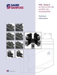
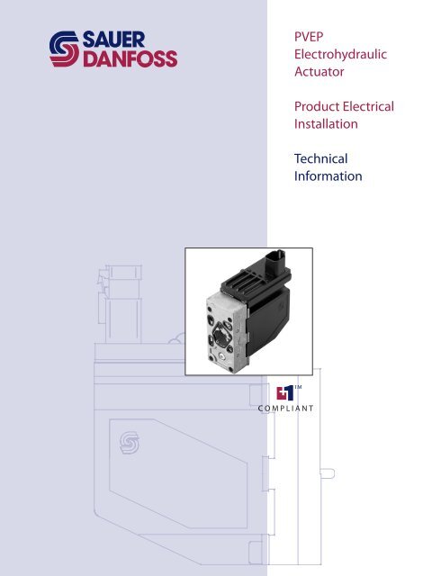
<strong>PVEP</strong><br />
<strong>Electrohydraulic</strong><br />
<strong>Actuator</strong><br />
<strong>Product</strong> <strong>Electrical</strong><br />
Installation<br />
Technical<br />
Information
Revision History<br />
2 11022662 • Rev BA • Feb 2010<br />
<strong>PVEP</strong> <strong>Electrohydraulic</strong> <strong>Actuator</strong><br />
<strong>Product</strong> <strong>Electrical</strong> Installation Technical Information<br />
Revisions<br />
Table of Revisions<br />
Date Page Changed Rev.<br />
8 Feb, 2010 5-6 Proportional Valve Body drawing updated;<br />
Basic Concept/ Controller and <strong>PVEP</strong> drawing updated<br />
BA<br />
4 Apr, 2007 AA<br />
© 2010 <strong>Sauer</strong>-<strong>Danfoss</strong>. All rights reserved.<br />
<strong>Sauer</strong>-<strong>Danfoss</strong> accepts no responsibility for possible errors in catalogs, brochures and other printed material.<br />
<strong>Sauer</strong> -<strong>Danfoss</strong> reserves the right to alter its products without prior notice. This also applies to products already<br />
ordered provided that such alterations can be made without affecting agreed specifications. All trademarks in<br />
this material are properties of their respective owners. <strong>Sauer</strong>-<strong>Danfoss</strong>, the <strong>Sauer</strong>-<strong>Danfoss</strong> logotype, the <strong>Sauer</strong>-<br />
<strong>Danfoss</strong> S-icon, PLUS+1, What really matters is inside® and Know-How in Motion are trademarks of the <strong>Sauer</strong>-<br />
<strong>Danfoss</strong> Group.<br />
Front cover illustrations: F301383, 2412
<strong>PVEP</strong> <strong>Electrohydraulic</strong> <strong>Actuator</strong><br />
<strong>Product</strong> <strong>Electrical</strong> Installation Technical Information<br />
Contents<br />
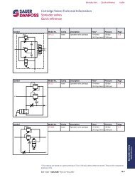
<strong>Product</strong> Overview <strong>Product</strong> Image ................................................................................................................................................. 4<br />
Code/ Part Numbers ...................................................................................................................................... 4<br />
Description/ Theory of Operation ............................................................................................................ 5<br />
Hydraulic Schematics .................................................................................................................................... 7<br />
<strong>Electrical</strong> Specifications ................................................................................................................................ 7<br />
<strong>Electrical</strong> Installation Pinout ................................................................................................................................................................. 8<br />
Pin Compatibility ............................................................................................................................................ 8<br />
Input/ Output Matrix ..................................................................................................................................... 8<br />
Mating Connector .......................................................................................................................................... 8<br />
Literature References Refer to PVG 32 Proportional Valves Technical Information 520L0344, PVG 100 Proportional<br />
Valves Technical Information 520L0720, PVE Series 4 for PVG 32, PVG 100 and PVG 120<br />
Technical Information 520L0553, Instructions for PVG Series 4 for <strong>PVEP</strong> 520L0921 for<br />
complete product electrical and mechanical specifications.<br />
Refer to <strong>PVEP</strong> Compliant Function Block User Manual 11020634 for compliant function<br />
block set-up information.<br />
Technical literature is available at: www.sauer-danfoss.com<br />
11022662 • Rev BA • Feb 2010<br />
3
<strong>Product</strong> Image<br />
4 11022662 • Rev BA • Feb 2010<br />
<strong>PVEP</strong> <strong>Electrohydraulic</strong> <strong>Actuator</strong><br />
<strong>Product</strong> <strong>Electrical</strong> Installation Technical Information<br />
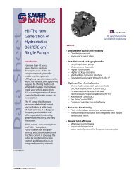
<strong>Product</strong> Overview<br />
The <strong>PVEP</strong> has two low frequency PWM inputs that determine the set point for main spool<br />
control in the valve. This differs from the standard PVE programme where an analogue<br />
ratio metric signal forms the input set point to the valve.<br />
The <strong>PVEP</strong> will be available in two versions, a standard <strong>PVEP</strong> and a <strong>PVEP</strong>-F for valves with<br />
float position option.<br />
This tech note will cover the control functionality for the <strong>PVEP</strong>.<br />
Code/ Part Numbers <strong>PVEP</strong><br />
<strong>PVEP</strong> proportional actuation Deutsch® DT connector<br />
Standard <strong>PVEP</strong> 157B4752
Description/<br />
Theory of Operation<br />
<strong>PVEP</strong> <strong>Electrohydraulic</strong> <strong>Actuator</strong><br />
<strong>Product</strong> <strong>Electrical</strong> Installation Technical Information<br />
<strong>Product</strong> Overview<br />
The philosophy of <strong>Sauer</strong>-<strong>Danfoss</strong> electrohydraulic actuation, type PVE, is integration<br />
of electronics, sensors and actuators into a single unit that interfaces directly to the<br />
proportional valve body.<br />
Proportional Valve Body<br />
P<br />
p<br />
11022662 • Rev BA • Feb 2010<br />
T<br />
P<br />
T<br />
V310134.A<br />
Closed Loop Control<br />
All the proportional actuators feature an integrated feedback transducer that measures<br />
spool movement in relation to the input signal, and by means of a solenoid valve<br />
bridge, controls the direction, velocity and position of the main spool of the valve.<br />
The integrated electronics compensate for flow forces on the spool, internal leakage,<br />
changes in oil viscosity, pilot pressure, etc. This results in lower hysteresis and better<br />
resolution. Furthermore the electronics enable built in safety like fault monitoring,<br />
directional indication and LED light indication.<br />
Closed Loop Control Schematic<br />
Set Point Solenoid<br />
Valve Bridge<br />
Feed Back Signal<br />
Transducer<br />
Spool or<br />
Piston<br />
Spool Position<br />
157-503.10<br />
5
Description/<br />
Theory of Operation<br />
(continued)<br />
Set point<br />
Position<br />
PWM<br />
to<br />
- +<br />
11 - 32 V<br />
-<br />
6 11022662 • Rev BA • Feb 2010<br />
<strong>PVEP</strong> <strong>Electrohydraulic</strong> <strong>Actuator</strong><br />
<strong>Product</strong> <strong>Electrical</strong> Installation Technical Information<br />
<strong>Product</strong> Overview<br />
Concept<br />
Basic Concept/ Controller and <strong>PVEP</strong><br />
Driver<br />
A<br />
Sense<br />
- Driver<br />
B<br />
Sense<br />
PVE<br />
Valve<br />
inch<br />
0.3<br />
0.2<br />
-0.2<br />
-0.3<br />
Spool travel<br />
mm<br />
7.5<br />
5.5<br />
-5.5<br />
-7.5<br />
Proportional<br />
Control range<br />
Float posistion<br />
80% 90%<br />
PWM B ratio<br />
[%]<br />
PWM A ratio<br />
V310137.A<br />
The <strong>PVEP</strong> is driven by two low current PWM inputs, called PWM_A and PWM_B. The duty<br />
cycle of the PWM signal determine the spool position.<br />
Duty Cycle Definition<br />
T = Period [s]<br />
Duty cycle [%] = (ti/T) * 100%<br />
ti = Time impulse (< V bat)<br />
ti tp tp = Time pause ( 0 voltage)<br />
In the <strong>PVEP</strong> the duty cycle of the pulse is measured as a true time difference<br />
measurement. The <strong>PVEP</strong> interprets the duty cycle and positions the spool accordingly.<br />
2410
Hydraulic Schematics <strong>PVEP</strong><br />
<strong>PVEP</strong> <strong>Electrohydraulic</strong> <strong>Actuator</strong><br />
<strong>Product</strong> <strong>Electrical</strong> Installation Technical Information<br />
<strong>Product</strong> Overview<br />
U s<br />
Input<br />
Signal<br />
LVDT<br />
Signal<br />
PWM<br />
<strong>Electrical</strong> Specifications The following technical data is from typical test results. For the hydraulic system<br />
a mineral based hydraulic oil with a viscosity of 21 mm 2 /second [102 SUS] and a<br />
temperature of 50° C [122° F] were used.<br />
Specifications<br />
Supply voltage Vbat range 10 to 32 Vdc<br />
Supply voltage Vbat maximum ripple 5%<br />
Supply voltage Vbat over voltage (maximum 5 minutes) 36 Vdc<br />
PWM control range (duty cycle) 10 to 80 %<br />
PWM float position control PWM_A = PWM_B = 90%<br />
PWM frequency 100 to 1000 Hz<br />
PWM input voltage swing 0 to > Vbat<br />
PWM input low voltage 0 to 0.6 Vdc<br />
PWM input high voltage 5 to 32 Vdc<br />
Input impedance (standard pull down) 5 kΩ<br />
Input capacitor --<br />
Power consumption 7 W<br />
Error voltage (fault monitoring) No fault = 0 Voltage Fault = Vbat<br />
All connector terminals are short circuit protected and protected against reverse connection<br />
(and their combinations)<br />
The main spool position feedback via the LVDT enables <strong>PVEP</strong> to control the proportional<br />
valve main spool very smoothly and accurately with a hysteresis of typical 3 to 4%. PWM<br />
frequency can be chosen between 100 to 1000 Hz for A or B channel.<br />
�Warning<br />
It’s up to the customer to decide on the required degree of safety for the system.<br />
11022662 • Rev BA • Feb 2010<br />
7
Pinout Pinout<br />
8 11022662 • Rev BA • Feb 2010<br />
<strong>PVEP</strong> <strong>Electrohydraulic</strong> <strong>Actuator</strong><br />
<strong>Product</strong> <strong>Electrical</strong> Installation Technical Information<br />
<strong>Electrical</strong> Installation<br />
Pin Connector<br />
1 PWM_A<br />
2 Error<br />
3 PWM_B<br />
4 No connection<br />
5 Ground<br />
6 U DC<br />
Pin Compatibility PLUS+1 Module Pin Type/ <strong>PVEP</strong> Pin Compatibility<br />
Input/ Output Matrix <strong>PVEP</strong> Input/ Output Matrix<br />
Pin Location<br />
PLUS+1 module pin type Acceptable use: Deutsch® connector pin number<br />
DOUT/PVG Pwr 1-3 6<br />
PWMOUT/DOUT/PVGOUT 1-3 1, 3<br />
Power ground - 5<br />
Dig in 2<br />
Duty cycle A-signal<br />
(pin 1)<br />
Duty cycle B-signal<br />
(pin 2)<br />
3<br />
2<br />
1<br />
4<br />
5<br />
6<br />
Function<br />
2411<br />
Error pin output<br />
(pin 3)<br />
0% 0%<br />
Notes<br />
<strong>PVEP</strong> <strong>Electrohydraulic</strong> <strong>Actuator</strong><br />
<strong>Product</strong> <strong>Electrical</strong> Installation Technical Information<br />
Notes<br />
11022662 • Rev BA • Feb 2010<br />
9
Our <strong>Product</strong>s<br />
Open circuit axial piston pumps<br />
Gear pumps and motors<br />
Fan drive systems<br />
Closed circuit axial piston pumps<br />
and motors<br />
Bent axis motors<br />
Hydrostatic transmissions<br />
Transit mixer drives<br />
Hydrostatic transaxles<br />
<strong>Electrohydraulic</strong>s<br />
Integrated systems<br />
Microcontrollers and software<br />
PLUS+1 GUIDE<br />
Displays<br />
Joysticks and control handles<br />
Sensors<br />
Orbital motors<br />
Inverters<br />
<strong>Electrohydraulic</strong> power steering<br />
Hydraulic power steering<br />
Hydraulic integrated circuits (HIC)<br />
Cartridge valves<br />
Directional spool valves<br />
Proportional valves<br />
11022662 • Rev BA • Feb 2010<br />
<strong>Sauer</strong>-<strong>Danfoss</strong> Mobile Power and Control Systems<br />
– Market Leaders Worldwide<br />
<strong>Sauer</strong>-<strong>Danfoss</strong> is a comprehensive supplier providing complete<br />
systems to the global mobile market.<br />
<strong>Sauer</strong>-<strong>Danfoss</strong> serves markets such as agriculture, construction,<br />
road building, material handling, municipal, forestry, turf care, and<br />
many others.<br />
We offer our customers optimum solutions for their needs and<br />
develop new products and systems in close cooperation and<br />
partner ship with them.<br />
<strong>Sauer</strong>-<strong>Danfoss</strong> specializes in integrating a full range of system<br />
components to provide vehicle designers with the most advanced<br />
total system design.<br />
<strong>Sauer</strong>-<strong>Danfoss</strong> provides comprehensive worldwide service for its<br />
products through an extensive network of Global Service Partners<br />
strategically located in all parts of the world.<br />
Local address:<br />
<strong>Sauer</strong>-<strong>Danfoss</strong> (US) Company<br />
2800 East 13th Street<br />
Ames, IA 50010, USA<br />
Phone: +1 515 239-6000<br />
Fax: +1 515 239 6618<br />
<strong>Sauer</strong>-<strong>Danfoss</strong> GmbH & Co. OHG<br />
Postfach 2460, D-24531 Neumünster<br />
Krokamp 35, D-24539 Neumünster, Germany<br />
Phone: +49 4321 871-0<br />
Fax: +49 4321 871 122<br />
www.sauer-danfoss.com<br />
<strong>Sauer</strong>-<strong>Danfoss</strong> ApS<br />
DK-6430 Nordborg, Denmark<br />
Phone: +45 7488 4444<br />
Fax: +45 7488 4400<br />
<strong>Sauer</strong>-<strong>Danfoss</strong>-Daikin LTD.<br />
Shin-Osaka TERASAKI 3rd Bldg. 6F<br />
1-5-28 Nishimiyahara, Yodogawa-ku<br />
Osaka 532-0004, Japan<br />
Phone: +81 6 6395 6066<br />
Fax: +81 6 6395 8585