Day and Night VS Air Handler Installation.pdf
Day and Night VS Air Handler Installation.pdf
Day and Night VS Air Handler Installation.pdf
You also want an ePaper? Increase the reach of your titles
YUMPU automatically turns print PDFs into web optimized ePapers that Google loves.
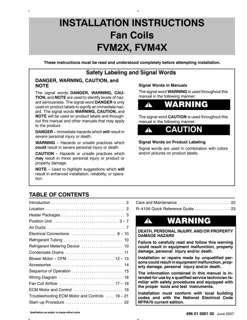
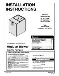
INSTALLATION INSTRUCTIONSFan CoilsFVM2X, FVM4XThese instructions must be read <strong>and</strong> understood completely before attempting installation.DANGER, WARNING, CAUTION, <strong>and</strong>NOTEThe signal words DANGER, WARNING, CAU-TION, <strong>and</strong> NOTE are used to identify levels of hazardseriousness. The signal word DANGER is onlyused on product labels to signify an immediate hazard.The signal words WARNING, CAUTION, <strong>and</strong>NOTE will be used on product labels <strong>and</strong> throughoutthis manual <strong>and</strong> other manuals that may applyto the product.DANGER -- Immediate hazards which will result insevere personal injury or death.WARNING -- Hazards or unsafe practices whichcould result in severe personal injury or death.CAUTION -- Hazards or unsafe practices whichmay result in minor personal injury or product orproperty damage.NOTE -- Used to highlight suggestions which willresult in enhanced installation, reliability, or operation.Safety Labeling <strong>and</strong> Signal WordsSignal Words in ManualsThe signal word WARNING is used throughout thismanual in the following manner:WARNING!WARNINGThe signal word CAUTION is used throughout thismanual in the following manner:!CAUTIONSignal Words on Product LabelingSignal words are used in combination with colors<strong>and</strong>/or pictures on product labels.TABLE OF CONTENTSIntroduction .................................... 2Location ....................................... 2Heater Packages ............................... 3Position Unit ................................ 3 -- 7<strong>Air</strong> Ducts ...................................... 7Electrical Connections ...................... 8 -- 10Refrigerant Tubing ............................. 10Refrigerant Metering Device .................... 10Condensate Drains ............................ 11Blower Motor -- CFM ....................... 12 -- 13Accessories .................................. 14Sequence of Operation ......................... 15Wiring Diagram ............................... 16Fan Coil <strong>Air</strong>flow ........................... 17 -- 19ECM Motor <strong>and</strong> Control ........................ 19Troubleshooting ECM Motor <strong>and</strong> Controls .... 19 -- 21Start--up Procedure ............................ 22Care <strong>and</strong> Maintenance ......................... 22R--410A Quick Reference Guide ................. 23! WARNINGDEATH, PERSONAL INJURY, AND/OR PROPERTYDAMAGE HAZARDFailure to carefully read <strong>and</strong> follow this warningcould result in equipment malfunction, propertydamage, personal injury <strong>and</strong>/or death.<strong>Installation</strong> or repairs made by unqualified personscould result in equipment malfunction, propertydamage, personal injury <strong>and</strong>/or death.The information contained in this manual is intendedfor use by a qualified service technician familiarwith safety procedures <strong>and</strong> equipped withthe proper tools <strong>and</strong> test instruments.<strong>Installation</strong> must conform with local buildingcodes <strong>and</strong> with the National Electrical CodeNFPA70 current edition.Specifications are subject to change without notice496 01 5001 02 June 2007
INSTALLATION INSTRUCTIONSINTRODUCTIONModels FVM2X <strong>and</strong> FVM4X are designed for maximumflexibility <strong>and</strong> can be used for upflow, horizontal left orright, <strong>and</strong> downflow applications (accessory kit requiredfor downflow or horizontal right).These units are designed to meet the low air leakrequirements currently in effect. Because of this, the unitsneed special attention in the condensate pan <strong>and</strong> drainconnection area <strong>and</strong> when brazing tubing.LOCATIONSelect the best position which suits the installation siteconditions. The location should provide adequatestructural support, space in the front of the unit for serviceaccess, clearance for return air <strong>and</strong> supply ductconnections, space for refrigerant piping connections <strong>and</strong>condensate drain line connections. If heaters are beinginstalled make sure adequate clearance is maintainedfrom supply duct work. Refer to Clearances in Figure 1.If the unit is located in an area of high humidity, nuisancesweating of casing may occur. On these installations awrap of 2” fiberglass insulation with a vapor barrier isrecommended.NOTE: Internal filter can be accessed from separate filterdoor. If the filter can NOT be easily accessed, a remoteFan Coils: FVM2X, FVM4XFour fan coil sizes will combine with various outdoor unitsizes to offer systems ranging from 1½ -- 5 tons (18,000-- 60,000 BTUH) nominal cooling capacity.All models have a factory installed <strong>and</strong> appropriatelysized hard shut--off TXV metering device.Factory--authorized, field--installed electric heaterpackages are available in sizes 5 kW through 30 kW. SeeProduct Specification literature for available accessorykits.filter is recommended. Refer to ACCA Manual D forremote filter sizing.! WARNINGFIRE HAZARDFailure to maintain proper clearances could resultin personal injury, death, <strong>and</strong>/or property damage.When heaters are installed, maintain clearancesfrom combustible materials as specified on unitrating plate. Do not use plastic lined or combustibleflexible ducting within 36 inches of the supplyendofthefancoil.Figure 1( OPENING)Clearances <strong>and</strong> Unit DimensionsFABEREQUIRED CLEARANCES - ALL MODELS (inches)No HeatersAll Sides0From Supply Duct0All Sides0With Heaters From First 3 feet of Supply Duct to Combustibles 1From Supply Duct to Combustibles after 3 feet0FVM DIMENSIONSUnit Size A B C D E F G2400 15 3/4 11 19 3/16 15 5/8 22 1/16 17 5/8 213600 19 1/4 11 19 3/16 19 1/8 22 1/16 21 1/8 214800 19 1/4 11 19 3/16 19 1/8 22 1/16 21 1/8 216000 22 3/4 11 19 3/16 22 11/16 22 1/16 24 11/16 24FVMUnit Size H2400 42 11/163600 53 7/164800 53 7/166000 59 3/16HGCD(SERVICE ACCESS)( OPENING)38 - 11 - 822 Specifications are subject to change without notice496 01 5001 02
INSTALLATION INSTRUCTIONSHEATER PACKAGESFactory approved, field installed, UL listed heaterpackages are available from the equipment supplier. Seeunit rating plate for a list of factory approved heaters.POSITION UNITUnit can st<strong>and</strong> or lie on floor, or hang from ceiling or wall.Allow space for wiring, piping, <strong>and</strong> servicing unit.! CAUTIONPROPERTY DAMAGE HAZARDFailure to follow this caution may result in propertydamageA field fabricated auxiliary drain pan, with a separatedrain is REQUIRED for all installations over afinished living space or in any area that may bedamaged by overflow from a restricted main drainpan. In some localities, local codes require an auxiliarydrain pan for ANY horizontal installation.Fan Coils: FVM2X, FVM4XHeaters that are not factory approved could causedamage which would not be covered under theequipment warranty.A. UPFLOW INSTALLATIONIf return air is to be ducted through a floor, install duct flushwith floor. Set unit on floor over opening.Side return is a field option on slope coil models. Cutopening per dimensions shown in Figure 2. Afield--supplied bottom closure is required.Figure 2Slope Coil Unit in Upflow ApplicationPOWER ENTRYOPTIONSFIELD SUPPLIEDSUPPLY DUCTFRONT SERVICE CLEARANCE24 - 48 models = 21”60 model = 24”A-COILUNITSLOW VOLTENTRYOPTIONSSLOPE COIL UNITModel Size A36 19"UPFLOW/DOWNFLOWSECONDARY DRAIN1½”UPFLOW/DOWNFLOWPRIMARY DRAIN19”2½”AFIELD MODIFIEDSIDE RETURNLOCATION FORSLOPE COILUNITS ONLYUPFLOW/DOWNFLOWSECONDARY DRAINUPFLOW/DOWNFLOWPRIMARY DRAINFIELD SUPPLIEDRETURN PLENUM496 01 5001 02 Specifications are subject to change without notice3
INSTALLATION INSTRUCTIONSFan Coils: FVM2X, FVM4XFigure 32 SCREWSREAR CORNERBRACKETModular Unit AssemblyBLOWER BOX2 SCREWS2 SCREWSCOIL BOXB. MODULAR UNITSFVM fan coils in sizes 4800 & 6000 are two--piecemodular units. Modular construction allows installer todisassemble unit into two (2) components, coil box <strong>and</strong>blower box, for ease of installation (refer to Figure 3).To disassemble unit, remove rear corner brackets byremoving two (2) screws which secure brackets (refer toFigure 3). Remove either two (2) screws in each frontcorner of coil box, or two (2) screws in blower box. Do notremove all four (4) screws in each corner. Sections maynow be separated by lifting top section from lower section.To reassemble, reverse above procedure. Be certain toreinstall all fasteners when reassembling.C. HORIZONTAL INSTALLATIONUnit must NOT be installed with access panels facing upor down. Access panels must only face to the side.FVM models are factory built for horizontal left installation(refer to Figure 4 <strong>and</strong> Figure 5). They can be fieldconverted to horizontal right (accessory Gasket Kitrequired -- EBAC01GSK).NOTE: When suspending unit from ceiling, dimples incasing indicate suitable location of screws for mountingmetal support straps (refer to Figure 4).NOTE: For optimum condensate drainage performancein horizontal installations, unit should be leveled along itslength <strong>and</strong> width.Figure 4Slope Coil In Horizontal Left Application (FVM factory configuration)A-COILHORIZONTAL LEFTFIELDSUPPLIEDHANGINGSTRAPSSECONDARYDRAINPRIMARYDRAINSECONDARYDRAINFRONT SERVICE CLEARANCE(FULL FACE OF UNIT)24 - 48 models = 21”60 model = 24”LOW VOLTENTRYOPTIONS1¾”FILTER ACCESSCLEARANCEPOWERENTRYOPTIONSPRIMARYDRAIN4 Specifications are subject to change without notice496 01 5001 02
INSTALLATION INSTRUCTIONSFan Coils: FVM2X, FVM4XFigure 5A -Coil in Horizontal Left Application (FVM factory configuration)AFACTORY SHIPPEDHORIZONTAL LEFTAPPLICATIONBCCOILBRACKETCOILSUPPORTRAILDRAIN PANSUPPORTBRACKETCOILBRACKETHORIZONTALDRAIN PANAIR SEALASSEMBLYREFRIGERANTCONNECTIONSPRIMARY DRAINHORIZONTAL LEFTSECONDARY DRAINHORIZONTAL LEFTHorizontal Right Conversion of Units With SlopeCoils1. Remove blower <strong>and</strong> coil access panel <strong>and</strong> fittingpanel (refer to Figure 6).2. Remove coil mounting screw securing coilassembly to right side casing flange.3. Remove coil assembly.4. Lay fan coil unit on its right side <strong>and</strong> reinstall coilassembly with condensate pan down (refer toFigure 6).5. Attach coil to casing flange using coil mountingscrew previously removed.6. Make sure the pan cap in the fitting door is properlyseated on the fitting door to retain the low air leakrating of the unit.Figure 6Horizontal Right Conversion Applications - Slope CoilCOIL MOUNTINGSCREWBLOWERASSEMBLYSLOPE COILSKIDRAINPANREFRIGERANTCONNECTIONSPRIMARY DRAINSECONDARY DRAIN496 01 5001 02 Specifications are subject to change without notice5
INSTALLATION INSTRUCTIONS7. Add gaskets from the Gasket Accessory Kit --EBAC01GSK.Fan Coils: FVM2X, FVM4X8. Align holes with tubing connections <strong>and</strong>condensate pan connections, <strong>and</strong> reinstall accesspanels <strong>and</strong> fitting panel. Make sure liquid <strong>and</strong>suction tube grommets are in place to prevent airleaks <strong>and</strong> cabinet sweating.Figure 7Conversion for Horizontal Right Applications - A -CoilCOILSUPPORTRAILREFRIGERANTCONNECTIONSAIR SEALASSEMBLYAHORIZONTALRIGHTAPPLICATIONCOILBRACKETBCDRAIN PANSUPPORTBRACKETCOILSUPPORTRAILCOILBRACKETHORIZONTALDRAIN PANPRIAMRY DRAINHORIZONTAL RIGHTSECONDARY DRAINHORIZONTAL RIGHTHorizontal Right Conversion of Units With A -Coils1. Remove blower <strong>and</strong> coil access panel <strong>and</strong> fittingpanel (refer to Figure 7).2. Remove metal clip securing fitting panel tocondensate pan. Remove fitting panel.3. Remove two (2) snap--in clips securing A--coil inunit.4. Slide coil <strong>and</strong> pan assembly out of unit.5. Remove horizontal drain pan support bracket fromcoil support rail on left side of unit <strong>and</strong> reinstall oncoil support rail on right side of unit.6. Convert air--seal assembly for horizontal right.a. Remove air--seal assembly from coil by removingfour (4) screws (refer to Figure 7).b. Remove air splitter (B) from coil seal assembly byremoving three (3) screws. (factory--shippedinset.)c. Remove filler plate (A) <strong>and</strong> install air splitter (B)in place of filler plate.d. Install filler plate (A) as shown in horizontal rightapplication.e. Remove condensate troughs (C) <strong>and</strong> install onopposite tube sheets.f. Install hose onto plastic spout.7. Install horizontal pan on right side of coil assembly.8. Slide coil assembly into casing. Be sure coilbracket on each corner of vertical pan engages coilsupport rails.9. Reinstall two (2) snap--in clips to correctly position<strong>and</strong> secure coil assembly in unit. Be sure clip withlarge offsets is used on right side of unit to securehorizontal pan.10. Remove two (2) oval fitting caps from left side ofthe coil, access panel, <strong>and</strong> fitting panel.11. Remove insulation knockouts on right side of coilaccess panel12. Remove two (2) oval coil access panel plugs <strong>and</strong>reinstall into holes on left side of coil access panel<strong>and</strong> fitting panel.13. Install condensate pan fitting caps (from Step 10)in the right side of the coil door making sure that thecap snaps <strong>and</strong> seats cleanly on the back side of thecoil door. Make sure no insulation interferes withseating of the cap.14. Reinstall access fitting panels, aligning holes withtubing connections <strong>and</strong> condensate panconnections. Be sure to reinstall metal clipbetween fitting panel <strong>and</strong> vertical condensate pan.15. After brazing, make sure liquid <strong>and</strong> suction tubegrommets are in place to prevent air leaks <strong>and</strong>cabinet sweating.6 Specifications are subject to change without notice496 01 5001 02
INSTALLATION INSTRUCTIONSF. DOWNFLOW INSTALLATION! CAUTIONPRODUCT OR PROPERTY DAMAGE HAZARDFailure to follow this caution may result in productor property damageThe conversion of the fan coil to downflow requiresspecial procedures for the condensatedrains on both A -coil <strong>and</strong> Slope -coil units. Thevertical drains have an overflow hole between theprimary <strong>and</strong> secondary drain holes. This hole isplugged for all applications except downflow, <strong>and</strong>must be used for downflow.Failure to follow instructions could result in personalinjury or product <strong>and</strong> property damage.In this application, field conversion of the evaporator coilis required using accessory Downflow Kit along with anaccessory Base Kit. Set unit on floor over opening <strong>and</strong>use 1/8” to 1/4” thick fireproof resilient gasket betweenduct, unit, <strong>and</strong> floor. Refer to installation instructionspackaged with accessory kit. See Product Specificationliterature for kit part numbers.During the conversion process, removed the plastic capcovering the vertical drains only <strong>and</strong> discard.Remove the plug from the overflow hole <strong>and</strong> discard.At completion of the downflow installation, caulk aroundthe vertical pan fitting to door joint to retain low air leakperformance of the unit.NOTE: Gasket kit number (EBAC01GSK) is alsorequired for all downflow applications to maintain low airleak/low sweat performance.G. MANUFACTURED HOUSING AND MOBILE HOMEAPPLICATIONS1. Fan coil unit must be secured to the structureusing field--supplied hardware.2. Allow a minimum of 24” clearance from accesspanels.AIR DUCTSConnect supply--air duct over the outside of ¾” flangesprovided on supply--air opening. Secure duct to flangeusing proper fasteners for type of duct used, <strong>and</strong> sealduct--to--unit joint.Duct connections flanges are provided on unit airdischarge connection.When using FVM units with 20kW, 24kW, <strong>and</strong> 30kWelectric heaters, maintain a 1” clearance fromcombustible materials to discharge plenum <strong>and</strong> ductworkfor a distance of 36” from unit. Use accessory downflowbase to maintain proper clearance on downflowinstallations.Use flexible connectors between duct work <strong>and</strong> unit toprevent transmission of vibration. When electric heater isinstalled, use heat--resistant material for flexibleconnector between duct work <strong>and</strong> unit at dischargeFan Coils: FVM2X, FVM4X3. Recommended method of securing for typicalapplications:a. If fan coil is away from wall, attach pipe strap totop of fan coil using No. 10 self tapping screws.Angle strap down <strong>and</strong> away from back of fan coil,remove all slack, <strong>and</strong> fasten to wall stud ofstructure using 5/16” lag screws. Typical bothsides of fan coil.b. If fan coil is against wall, secure fan coil to wallstud using 1/8” wide right--angle brackets. Attachbrackets to fan coil using No. 10 self tappingscrews <strong>and</strong> to wall stud using 5/16” lag screws(refer to Figure 8).Figure 8Mobile Home or ManufacturedHousing Applications4” MAX4” MAXSECURE FAN COIL TO STRUCTUREUNIT AWAY FROM WALLPIPE STRAP(TYPICAL BOTH SIDES)ORUNIT AGAINST WALL1/8” INCH THICKANGLE MOUNTINGBRACKET(TYPICAL BOTH SIDES)DOWN FLOWBASE KITSECURE UNIT TO FLOORANGLE BRACKET OR PIPE STRAPconnection. Duct work passing through unconditionedspace must be insulated <strong>and</strong> covered with vapor barrier.Duct work Acoustical TreatmentMetal duct systems that do not have a 90 degree elbow<strong>and</strong> 10 feet of main duct before first branch takeoff mayrequire internal acoustical insulation lining. As analternative, fibrous duct work may be used if constructed<strong>and</strong> installed in accordance with the latest edition ofSMACNA construction st<strong>and</strong>ard on fibrous glass ducts.Both acoustical lining <strong>and</strong> fibrous duct work shall complywith National Fire Protection Association as tested by ULSt<strong>and</strong>ard 181 for Class 1 air ducts.496 01 5001 02 Specifications are subject to change without notice7
INSTALLATION INSTRUCTIONSELECTRICAL CONNECTIONSOn units with a factory installed disconnect with pull--outremoved, service <strong>and</strong> maintenance can be safelyperformed on only the load side of the control package.NOTE: Before proceeding with electrical connections,make certain that supply voltage, frequency, phase, <strong>and</strong>circuit ampacity are as specified on the unit rating plate.See unit wiring label for proper field high <strong>and</strong> low voltagewiring. Make all electrical connections in accordance withthe NEC <strong>and</strong> any local codes or ordinances that mayapply. Use copper wire only. The unit must have aseparate branch electric circuit with a field--supplieddisconnect switch located within sight from, <strong>and</strong> readilyaccessible from the unit.! WARNINGELECTRICAL SHOCK or UNIT DAMAGE HAZARDFailure to follow this warning could result in personalinjury or death.Turn off the main (remote) disconnect device beforeworking on incoming (field) wiring .Incoming (field) wires on the line side of the disconnectfound in the fan coil unit remain live, evenwhen the pull -out is removed. Service <strong>and</strong> maintenanceto incoming (field) wiring cannot be performeduntil the main disconnect switch (remoteto the unit) is turned off.! WARNINGELECTRICAL SHOCK or UNIT DAMAGE HAZARDFailure to follow this warning could result in personalinjury, death, <strong>and</strong>/or unit damage.If a disconnect switch is to be mounted on unit, selecta location where drill <strong>and</strong> fasteners will notcontact electrical or refrigeration components.A. LINE VOLTAGE CONNECTIONSIf unit contains an electric heater, remove <strong>and</strong> discardpower plug from fan coil <strong>and</strong> connect male plug fromheater to female plug from unit wiring harness. (Refer toElectric Heater <strong>Installation</strong> Instructions.) For units withoutelectric heat:1. Connect 208/230V power leads from fielddisconnect to yellow <strong>and</strong> black stripped leads.2. Connect ground wire to unit ground lug.Check all factory wiring per unit wiring diagram <strong>and</strong>inspect factory wiring connections to be sure none wereloosened in transit or installation.Fan Coils: FVM2X, FVM4XB. 24V CONTROL SYSTEMControl System Connections to Fan Control BoardRefer to unit wiring instructions for recommended wiringprocedures. Use 18 AWG color--coded, insulated (35 ˚Cminimum) wires to make the low--voltage connectionsbetween the thermostat, the unit, <strong>and</strong> the outdoorequipment. If the thermostat is located more than 100 feetfrom the unit (as measured along the low voltage wire),use 16 AWG color--coded, insulated (35 ˚C minimum)wire. Fan Control Board is circuited for single--stageheater operation. When additional heater staging isdesired using outdoor thermostats of Heat Staging,remove Jumper J2 on Fan Control Board to enablestaging.All wiring must be NEC Class 1 <strong>and</strong> must be separatedfrom incoming power leads. Refer to outdoor unit wiringinstructions for additional wiring recommendations.Connect low--voltage leads to thermostat <strong>and</strong> outdoorunit (refer to Figure 9, Figure 10, Figure 11, Figure 12).C. HEAT STAGINGHeat Staging OptionHeat Staging of the electric heat package is possiblewhen the FVM is installed as a part of a single--stage heatpump system using a two--stage programmablethermostat, or capable zoning control <strong>and</strong> <strong>and</strong> one (1) ofthe following electric heat packages:Relay heaters EHK10AKN, EHK10AKB, EHK15AK(F,B),EHK18AHN, EHK20AK(F,B) EHK25AHCF, orEHK30AHCF.Complete system low--voltage wiring as shown inFigure 9, Figure 10, Figure 11, Figure 12.NOTE: Where local codes require thermostat wiring berouted through conduit or raceways, splices can be madeinside the fan coil unit. All wiring must be NEC Class 1 <strong>and</strong>must be separated from incoming power leads.A factory--authorized disconnect kit is available forinstallation of 5 kW through 10 kW applications. Whenelectric heat package with circuit breakers are installed,the circuit breaker can be used as a disconnect.D. MANUFACTURED HOUSINGIn manufactured housing applications, the Code ofFederal Regulations, Title 24, Chapter XX, Part 3280.714requires that supplemental electric heat be locked out atoutdoor temperatures above 40 ˚F. except for a heatpump defrost cycle. In some applications, an outdoorthermostat may be required. Refer to thermostatinstructions for details.8 Specifications are subject to change without notice496 01 5001 02
INSTALLATION INSTRUCTIONSFan Coils: FVM2X, FVM4XFigure 9FVM Fan Coil Wiring withsingle -stage <strong>Air</strong> ConditionerFigure 11FVM Fan Coil Wiring withsingle -stage Heat PumpINDOOR CONTROLFAN COILINDOOR CONTROLFAN COILHEAT STAGE 2N/AHEAT STAGE 1O/W2Y1/W2W/W1W2Y1W1REMOVE J2 JUMPERFOR HEAT STAGINGR<strong>VS</strong> COOLINGHEAT STAGE 3HEAT STAGE 2HEAT/COOLSTAGE 1O/W2Y1/W2W/W1Y/Y2OW2W1Y/Y2OREMOVE J2 JUMPERFOR HEAT STAGINGW2YCOOL STAGE 1Y/Y2Y/Y2YFANGGFANGG24 VAC HOTRRR24 VAC HOTRRY1ODEHUMIDIFYDHUMHDEHUMIDIFYDHUMH24 VAC COMMCCC24 VAC COMMHUMIDIFYN/AOUTDOORCHUMBS1CHUMIDIFIER(24 VAC)OUTDOORSENSORCHUMIDIFYR<strong>VS</strong> HEATINGOUTDOORHUMBS1S2HUMIDIFIER(24 VAC)OUTDOORSENSORS2Figure 10FVM Fan Coil wiring withtwo -stage <strong>Air</strong> ConditioningFigure 12INDOOR CONTROLFVM Fan Coil wiring withtwo -stage Heat PumpFAN COILINDOOR CONTROLFAN COILR<strong>VS</strong> COOLINGO/W2OOHEAT STAGE 2HEAT STAGE 1COOL STAGE 1O/W2W/W1Y1/W2W2W1Y1REMOVE J2 JUMPERFOR HEAT STAGINGYHEAT/COOLSTAGE 1HEAT STAGE 3HEAT/COOLSTAGE 2FANY1/ W2W/W1Y/Y2GY1W1W2Y/Y2YW2REMOVE J2JUMPER FORHEAT STAGINGY2COOL STAGE 2Y/Y2Y/Y2Y224 VAC HOTRGFANGGRR24 VAC HOTRRRDEHUMIDIFYDHUMHO24 VAC COMMCCCDEHUMIDIFY24 VAC COMMHUMIDIFYN/AOUTDOORDHUMCHUMBS1HCHUMIDIFIER(24 VAC)OUTDOORSENSORCHUMIDIFYR<strong>VS</strong> HEATINGOUTDOORHUMBS1S2HUMIDIFIER(24 VAC)OUTDOORSENSORS2496 01 5001 02 Specifications are subject to change without notice9
INSTALLATION INSTRUCTIONSFan Coils: FVM2X, FVM4XFigure 13Transformer ConnectionsSECONDARYBROWNREDF. GROUND CONNECTIONSNOTE: Use UL listed conduit <strong>and</strong> conduit connectors forconnecting supply wire(s) to unit to obtain propergrounding. Grounding may also be accomplished byusing grounding lugs provided in control box. Use or dualor multiple supply circuits will require grounding of eachcircuit to ground lugs provided on unit <strong>and</strong> heaters.! WARNINGC208230BLACKPRIMARYYELLOWE. TRANSFORMER INFORMATIONTransformer is factory wired for 230V operation. For208V applications, disconnect the black wire from the230V terminal on transformer <strong>and</strong> connect it to the 208Vterminal (refer to Figure 13).The secondary circuit of transformer is protected by a 5amp fuse mounted on Fan Control Board.REFRIGERANT TUBINGUse accessory tubing package or field--supplied tubing ofrefrigerant grade. Insulate entire suction tube iffield--supplied tubing is used. Tubing package has aninsulated suction. Do not use damaged, dirty, orcontaminated tubing because it may plug refrigerant flowcontrol device.Always evacuate coil <strong>and</strong> field--supplied tubing to 500microns before opening outdoor unit service valve.! CAUTIONPRODUCT DAMAGE HAZARDFailure to follow this caution may result in productdamage.Braze with Sil -Fos or Phos -copper alloy on copper-to -copper joints <strong>and</strong> wrap a wet cloth aroundrear of fitting to prevent damage to TXV.REFRIGERANT METERING DEVICEFVM fan coils have a factory installed hard shut--off TXVdesigned only for use with R--22 <strong>and</strong> R--410Arefrigerants. Use only with outdoor units designed forcorresponding refrigerants.TXV is factory set <strong>and</strong> not field adjustable.ELECTRICAL SHOCK HAZARDFailure to establish uninterrupted or unbrokenground could result in personal injury <strong>and</strong>/ordeath.According to NEC, ANSI/NFPA 70, <strong>and</strong> localcodes, the cabinet must have an uninterrupted orunbroken ground in order to minimize potentialfor personal injury or death if an electrical faultshould occur. The ground may consist of electricalwire or metal conduit when installed in accordancewith existing electrical codes. If conduitconnection uses reducing washers, a separateground wire must be used.Size <strong>and</strong> install refrigerant lines according to informationprovided with outdoor unit. Route refrigerant lines to thefan coil in a manner that will not obstruct service access tothe unit or removal of the filter.1. Cut tubing to correct length.2. Hold coil stubs steady to avoid bending ordistorting.3. Fit refrigerant lines into coil stubs. Insert tube intosweat connection on unit until it bottoms.4. Wrap TXV <strong>and</strong> nearby tubing with a heat--sinkingmaterial such as a wet cloth.5. Wrap a heat sinking material such as a wet clothbehind braze joints.6. Braze connection using a silver bearing ornon--silver brazing materials (Sil--Fos orPhos--copper alloy). Do not use solder (matriceswhich melt below 800_F). Consult local coderequirements.7. After brazing, allow joints to cool. Evacuate coil <strong>and</strong>tubing system to 500 microns using deep vacuummethod.! CAUTIONPRODUCT DAMAGE HAZARDFailure to follow this caution may result in productdamage.This Fan Coil has a hard shut -off TXV metering device.A compressor Hard Start Kit is REQUIRED inall applications where the matching outdoor unithas a single -phase reciprocating compressor.10 Specifications are subject to change without notice496 01 5001 02
INSTALLATION INSTRUCTIONSCONDENSATE DRAINSUnits are provided with primary <strong>and</strong> secondary ¾” NPTdrain connections. Refer to Figure 2 though Figure 7 toidentify the primary <strong>and</strong> secondary locations. To preventproperty damage <strong>and</strong> achieve optimum drainageperformance, BOTH primary <strong>and</strong> secondary drain linesshould be installed <strong>and</strong> include properly sizedcondensate traps (refer to Figure 14). Factory approvedcondensate traps are available (accessory part numberEBAC01CTK).To connect drain lines, the drain connection knock--outsmust be removed. Use a knife to start the opening nearthe tab <strong>and</strong> using pliers, pull the tab to remove theknock--out. Clean the edge of the opening if necessary.After drain fittings are installed, caulk the seam betweenthe fitting <strong>and</strong> the cover to retain the low leak rating of theunit.It is recommended the PVC fittings be used on the plasticcondensate pan. Do not over--tighten. Finger--tightenplus 1½ turns. Use pipe dope, to ensure proper seal.Install traps in the condensate lines as close to the coil aspossible (refer to Figure 16), but avoid blocking filteraccess panel.Install drain lines below the bottom of the drain pan <strong>and</strong>pitch the drain lines down from the coil at least ¼ inch perfoot of run. Horizontal runs over 15 feet long must alsohave an anti--siphon air vents (st<strong>and</strong> pipes), installedahead of the horizontal runs. Extremely long horizontalruns may require oversized drain lines to eliminate airtrapping.Route primary drain line to the outside or to a floor drain.Check local codes before connecting to a waste (sewer)line.Route the secondary drain line to a place in compliancewith local installation codes where it will be noticed whenunit is operational. Condensate flowing from secondary(overflow) drain indicates a plugged primary drain -- unitrequires service or water damage will occur.Prime all traps, test for leaks, <strong>and</strong> insulate drain lineswhere sweating could cause water damage. Consult localcodes for additional requirements or precautions.If a gravity drain cannot be used, install a condensatepump. Install the pump as close to the indoor section aspossible.! CAUTIONPRODUCT or PROPERTY DAMAGE HAZARDFailure to follow this caution may result in productor property damage.Use only full size P -traps in the condensate line(refer to Figure 14). Shallow, running traps are inadequate<strong>and</strong> DO NOT allow proper condensatedrainage (refer to Figure 15).Figure 14UNITFigure 15Figure 16Fan Coils: FVM2X, FVM4XRecommended Condensate Trap2” MIN2” MINInsufficient Condensate TrapDO NOT USE SHALLOW RUNNING TRAPS!Condensate DrainFILTERACCESSPANELSECONDARY DRAIN WITHAPPROPRIATE TRAP REQUIRED(USE FACTORY KIT ORFIELD -SUPPLIED TRAP)PRIMARY TRAP REQUIRED (USE FACTORY KIT ORFIELD -SUPPLIED TRAP OF PROPER DEPTH.STANDARD P -TRAPS ARE NOT SUFFICIENT. SEEFIGURE OF RECOMMENDED CONDENSATE TRAP)496 01 5001 02 Specifications are subject to change without notice11
INSTALLATION INSTRUCTIONSBLOWER MOTOR - CFMFAN CONTROL BOARD CONFIGURATION TAPSFan Control Board taps are used by the installer toconfigure a system. The ECM motor uses the selectedtaps to modify its operation to a pre--programmed table ofairflows (Refer to Table 2 <strong>and</strong> Table 3). <strong>Air</strong>flows arebased on system size or mode of operation <strong>and</strong> thoseairflows are modified in response to other inputs such asthe need for de--humidification. (Refer to Figure 17 <strong>and</strong>Figure 18).FVM fan coils must be configured to operate properly withsystem components with which it is installed. Tosuccessfully configure a basic system (see informationprinted on circuit board label located next to select pins),move the 6 select wires to the pins which match thecomponents used.Fan Coils: FVM2X, FVM4XNote that airflow marked is the airflow which will besupplied in emergency heat mode <strong>and</strong> heating mode onair conditioners when electric heat is the primary heatingsource.In heat pump heating mode when electric heaters areenergized, the ECM motor will run the higher of heatpump heating airflow <strong>and</strong> electric heater airflow to ensuresafe heater operation. The factory selection is the largestheater range approved. (Refer to Figure 17, A asindicated)Figure 18Fan Control BoardWiring ArrangementFigure 17Fan Control BoardLOW VOLTAGE TERMINAL BLOCKFAN CONTROL BOARDVIOSEC1 SEC2AUX HEAT KW/CFMJ2HRW1AC/HP SIZEW2ABCDVIOBLUORNBLKSEC1SEC2AUX HEAT KW/CFMA B C DAC/HP SIZEA B C DSYSTEM TYPEAC HP-COMFORT HP-EFFNOMAC/HP CFM ADJUSTLOON/OFF DELAYHIJ2HRW 1W 2Y 1Y/Y 2GOBLUORNBLKWHTYELLOSYSTEM TYPEAC HP -COMFORT HP-EFFAC/HP CFM ADJUSTNOMLOON/OFF DELAY309000CEBD430226--01BHIENHCONTINUOUS FANMED HI YELHEATER/MOTORCESS430226--01BAUX1Y1Y/Y 2GOCHUM1AUX2 HUM224VACGRYEWHT309000ENHCFYELLOCONTINUOUS FANMED HI YELCEBD430226--01B CESS430226--01BAUX1AUX2HUM1HUM224VACHEATER/MOTORGRYMOLEX 12 -PIN CONNECTORA. AUXILIARY HEAT KW/CFMInstaller must select the auxiliary heat airflow approvedfor application with kW size heater installed. If no heater isinstalled, this step can be skipped. (Refer to Figure 17,A)The select pins are marked A, B, C, D. Heater kW rangescorresponding to each letter are listed in a chart on theunit wiring diagram. Refer to the unit wiring diagram <strong>and</strong>select the pin for the heater size being used (examplewiring diagram in Figure 21).The airflow must be greater than the minimum CFM forelectric heater application with the size system installedfor safe <strong>and</strong> continuous operation. (Refer to Table 4 <strong>and</strong>Table 5 for airflow delivery <strong>and</strong> minimum CFM.)B. AC/HP SIZESelect System Size InstalledThe factory setting for air conditioner or heat pump size isthe largest outdoor unit meant for application with themodel of fan coil purchased. Installer needs to select airconditioner or heat pump size to ensure that airflowdelivered falls within proper range for the size unitinstalled. This applies to all operational modes with theexception of electric heat modes. (Refer to Figure 17, B)The select pins are marked A, B, C, D. Outdoor unit sizescorresponding to each letter are listed in a chart on theunit wiring diagram. Refer to the unit wiring diagram <strong>and</strong>select the pin for the outdoor unit size being used(example wiring diagram in Figure 21).12 Specifications are subject to change without notice496 01 5001 02
INSTALLATION INSTRUCTIONSC. SYSTEM TYPESelect System Type Installed AC or HPThe type of system must be selected:1. AC -- <strong>Air</strong> Conditioner provides approximately 350CFM per ton for greater efficiency <strong>and</strong> humiditycontrol with the AC/HP CFM ADJUST set to thenominal (NOM) tap. (To achieve approximately 400CFM per ton move tap to (HI) position. Refer toappropriate airflow tables for exact CFM setting.)2. HP--COMFORT -- Heat Pump Comfort Providesapproximately 315 CFM per ton for higher thannormal heating air delivery temperature. Providesapproximately 350 CFM per ton cooling airflow forgood humidity removal with the AC/HP CFMADJUST set to the nominal (NOM) tap.3. HP--EFF -- Heat Pump Efficiency provides sameairflow for heating <strong>and</strong> cooling modes to increaseoverall HP efficiency; approximately 350 CFM perton with the AC/HP CFM ADJUST set to thenominal (NOM) tap.The factory setting is AC (Refer to Figure 17, C).D. AC/HP CFM ADJUSTSelect Medium, Low, or High <strong>Air</strong>flowTo provide airflow at rates described above, the AC/HPADJUST select is factory set to the nominal (NOM) tap.The adjust selections HI/LO will regulate airflow suppliedfor all operational modes, except non--heat pump heatingmodes.HI provides 15% airflow over nominal unit size selected<strong>and</strong> LO provides 10% airflow below nominal unit sizeselected.Adjust selection options are provided to adjust airflowsupplied to meet individual installation needs for suchthings as noise, comfort, <strong>and</strong> humidity removal. (Refer toFigure 17, D as indicated.)E. ON/OFF DELAYSelect desired time delay profileNOTE: Delay selections are active in cooling <strong>and</strong> heatpump heating modes only. Auxiliary heating modes havea one (1) minute off delay <strong>and</strong> zero (0) on delayprogrammed into the ECM motor that cannot beoverridden.Four (4) motor operation delay profiles are provided tocustomize <strong>and</strong> enhance system operation. (Refer toFigure 17, E as indicated.)Selection options are:1. 0/90: No on delay <strong>and</strong> 90 second off delay at 100%airflow (factory setting).2. 30/90: 30 second on delay with no airflow <strong>and</strong> 90second off delay at 100% airflow profile. Used whenit is desirable to allow system coils time toheat--up/cool--down in conjunction with the airflow.Fan Coils: FVM2X, FVM4X3. 0/0: No delay option. Used for servicing unit or whena thermostat is utilized to perform delay functions.4. ENH: enhanced selection, provides a 30 second ondelay with no airflow followed by 150 seconds at70% airflow, <strong>and</strong> no off delay for added comfort.This profile will minimize cold blow in heat pumpoperation <strong>and</strong> could enhance system efficiency.F. CONTINUOUS FANSelect desired fan speed when thermostat is set oncontinuous fanNOTE: If installed with a two--stage outdoor unit, do notselect HI speed continuous fan. If HI is selected, lowstage compression will also run HI fan speed possiblyresulting in insufficient dehumidification.1. LO speed -- factory setting, 50% cooling modeairflow.2. MED speed -- move connector to MED, 65% coolingmode airflow.3. HI speed -- move connector to HI, 100% coolingmode airflow. (Refer to Figure 17, F as indicated.)G. LOW -VOLTAGE CIRCUITFusing <strong>and</strong> ReferenceThe low--voltage circuit is fused by a board--mounted5--amp automotive fuse placed in series with thetransformer SEC2 <strong>and</strong> the R circuit. The C circuit of thetransformer is referenced to chassis ground through aprinted circuit run at SEC1 connected to metal st<strong>and</strong>offmarked with ground symbol.H. BASIC FAN COIL CONFIGURATIONThe following basic configuration of the fan coil willprovide ARI rated performance of an air conditioner:1. AUX HEAT KW/CFM -- Select the heater range forthe size electric heater installed.2. AC/HP SIZE -- Select system size installed.3. SYSTEM TYPE -- Select system type AC4. AC/HP CFM ADJUST -- Select NOM.5. ON/OFF DELAY -- Select 0/90 profile.6. CONTINUOUS FAN -- Select desired fan speedwhen thermostat is set to continuous fan.The following basic configuration of the fan coil willprovide ARI rated performance of a heat pump:1. AUX HEAT KW/CFM -- Select the heater range forthe size electric heater installed.2. AC/HP SIZE -- Select system size installed.3. SYSTEM TYPE -- Select system type HP--EFF4. AC/HP CFM ADJUST -- Select NOM.5. ON/OFF DELAY -- Select 0/90 profile.6. CONTINUOUS FAN -- Select desired fan speedwhen thermostat is set to continuous fan.496 01 5001 02 Specifications are subject to change without notice13
INSTALLATION INSTRUCTIONSFan Coils: FVM2X, FVM4XACCESSORIESA. ACCESSORY ELECTRIC HEATERSElectric heaters may be installed with the FVM fan coil perinstructions supplied with electric heater package. Seeunit rating plate for factory--approved electric heater kits.B. AUXILIARY TERMINALSThe AUX2 <strong>and</strong> HUM2 terminals on the Fan Control Boardare tied directly to the G terminal, <strong>and</strong> provide a 24 VACsignal whenever the G terminal is energized. (Refer toFigure 17 <strong>and</strong> Figure 18)C. HUMIDIFIER / HUMIDISTAT CONNECTIONSFan Control Board terminals HUM1 (directly connectedinternally to C on terminal block) <strong>and</strong> HUM2 (directlyconnected internally to G on terminal block) are providedfor direct connections to the low--voltage control of ahumidifier through a st<strong>and</strong>ard humidistat (refer toFigure 19). These terminals are energized with 24 VACwhen G thermostat signal is present (refer to Figure 22).Alternately, the 24VAC signal may be sourced from theW1 <strong>and</strong> C terminal block connections when electricheaters are used as a primary heating source (refer toFigure 20). When using a thermostat with humiditycontrol, the 24VAC signal may be sourced directly fromhumidity terminal on the thermostat. (Refer to Figure 9,Figure 10, Figure 11, orFigure 12.)Figure 19HUM 1(C)HUM 2(G)Figure 2024 -VAC(TERMINAL BOARDCONNECTIONS)C24 -VACWHumidifier WiringHUMIDISTATTO HUMIDIFIERHumidifier Wiring for Electric HeatPrimary Heating SourceHUMIDISTATTO HUMIDIFIERD. DEHUMIDIFY CAPABILITY WITH STANDARDHUMIDISTAT CONNECTIONLatent capacities for systems using the FVM fan coil arebetter than average systems. If increased latent capacityis an application requirement, the field wiring terminalblock provides a connection terminal (H) for use of ast<strong>and</strong>ard humidy sensor/control. The FVM will detect thehumidy sensor/control contact closing on increasinghumidity <strong>and</strong> reduce its airflow to approximately 80% ofnominal cooling mode airflow. This reduction will increasethe system latent capacity until the humidity falls to a levelwhich causes the humidity sensor/control to open itscontacts.When the contacts open, the airflow will return to 100% ofthe selected cooling airflow.14 Specifications are subject to change without notice496 01 5001 02
INSTALLATION INSTRUCTIONSSEQUENCE OF OPERATIONFVM fan coils will supply airflow in a range which is morethan twice the range of a st<strong>and</strong>ard fan coil. Each fan coilsize is designed to provide nominal cooling capacities at50 _F evaporator temperature <strong>and</strong> the required airflow inorder to match with any of four (4) different air conditioneror heat pump outdoor unit sizes. Table 1 outline the CFMrange for the different FVM fan coils.The blower motor is a true variable speed motor designedto deliver constant CFM. Constant CFM is valid forsystems with total external static pressure between 0.1<strong>and</strong> 0.7 inches water column.A. CONTINUOUS FANS Thermostat closes circuit R to G.S Blower runs at continuous fan airflow.B. COOLING MODE - SINGLE STAGES If indoor temperature is above temperature setpoint <strong>and</strong> humidity is below humidity set point,thermostat closes circuits R to G, R to Y/Y2 <strong>and</strong> R toO.NOTE: For single stage systems, do not use the Y1terminal.S Fan coil delivers single stage cooling airflow.C. COOLING MODE - TWO STAGES First stage (low) cooling: Thermostat closes circuitsto R to G, R to O, <strong>and</strong> R to Y1.SSFan coil delivers low stage cooling airflow.Second stage (high) cooling: Thermostat closescircuits to R to G, R to O, R to Y1 <strong>and</strong> R to Y/Y2.S Fan coil delivers high stage cooling airflow.D. COOLING MODE - DEHUMIDIFICATIONS If indoor temperature is above temperature setpoint <strong>and</strong> humidity is above humidity set point,thermostat closes circuits R to G, R to Y/Y2 <strong>and</strong> R toO <strong>and</strong> humidistat closes R to H.S The fan coil delivers airflow which is approximately80% of the nominal cooling airflow to increase thelatent capacity of the system.E. ELECTRIC HEAT HEATING MODES Thermostat closes circuit R to W/W1, or W2SFan coil delivers the selected electric heat airflow.Fan Coils: FVM2X, FVM4XF. HEAT PUMP HEATING MODE - SINGLE STAGES Thermostat closes circuits R to G <strong>and</strong> R to Y/Y2.NOTE: For single stage systems, do not use the Y1terminal.S Fan coil delivers single stage heat pump heatingairflow.G. HEAT PUMP HEATING MODE - TWO STAGES First stage (low) heating: Thermostat closes circuitsR to G <strong>and</strong> R to Y1.SSFan coil delivers low stage heating airflow.Second stage (high) heating: Thermostat closes Rto G, R to Y1 <strong>and</strong> R to Y/Y2.S Fan coil delivers high stage heating airflow.H. HEAT PUMP HEATING WITH AUXILIARYELECTRIC HEATS Thermostat closes circuits R to G, R to Y/Y2 <strong>and</strong>/orRtoY1withRtoW/W1orW2(<strong>and</strong>RtoOinthecase of defrost).In the event that electric heating is called for by thethermostat while the heat pump is also operating in eitherheating or defrost modes, the motor will modify its airflowoutput, if necessary, to provide an airflow which is definedas safe for the operation of the electric heater during heatpump operation. That airflow is the greater of the heatpump heating airflow <strong>and</strong> the electric heater only airflow.! CAUTIONELECTRICAL SHOCK or UNIT DAMAGE HAZARDFailure to carefully read <strong>and</strong> follow this CAUTIONwarning could result in equipment malfunction,property damage, personal injury <strong>and</strong>/or death.Disconnect power to unit before removing or replacingconnectors or servicing motor. Wait atleast five (5) minutes after disconnecting powerbefore opening motor.496 01 5001 02 Specifications are subject to change without notice15
INSTALLATION INSTRUCTIONSFan Coils: FVM2X, FVM4XFigure 21Wiring Diagram16 Specifications are subject to change without notice496 01 5001 02
INSTALLATION INSTRUCTIONSFan Coils: FVM2X, FVM4XFAN COIL AIRFLOWTable 1CFM RangeFan Coil Size Use with Outdoor Unit Size CFM RangeTable 2FanCoilSize24003600480060002400 18, 24, 30, 36 350 -- 12003600 24, 30, 36, 42 415 -- 14004800 30, 36, 42, 48 425 -- 16006000 36, 42, 48, 60 540 -- 2000Fan Coil <strong>Air</strong>flow Delivery (CFM) in Cooling Mode (A/C or HP)Outdoor Single StageTwo -Stage CoolingUnit CoolingHighLowFan OnlySize Nominal Dehum Nominal Dehum Nominal Dehum Low Med Hi18 525 420 Two--Stage outdoor unit not offered 350 420 52524 700 560 700 560 560 450 350 560 70030 875 700 Two--Stage outdoor unit not offered 440 700 87536 1050 840 1050 840 840 670 525 840 105024 700 560 700 560 560 450 415 560 70030 875 700 Two--Stage outdoor unit not offered 440 700 87536 1050 840 1050 840 840 670 525 840 105042 1225 980 Two--Stage outdoor unit not offered 615 980 122530 875 700 Two--Stage outdoor unit not offered 440 700 87536 1050 840 1050 840 840 670 525 840 105042 1225 980 Two--Stage outdoor unit not offered 615 980 122548 1400 1120 1400 1120 1120 900 700 1120 140036 1050 840 1050 840 840 670 540 840 105042 1225 980 Two--Stage outdoor unit not offered 615 980 122548 1400 1120 1400 1120 1120 900 700 1120 140060 1750 1400 1750 1400 1400 1120 875 1400 1750NOTES:1. The above airflows result with the AC/HP CFM ADJUST select jumper set on NOM.2. <strong>Air</strong>flow can be adjusted +15% or --10% by selecting Hi or Lo respectively for all modes except fan only.3. Dry coil at 230 volts <strong>and</strong> with 10kW heater <strong>and</strong> filter installed.4. <strong>Air</strong>flows shown are valid for systems with total static pressure between 0.1 <strong>and</strong> 0.7 in wc.496 01 5001 02 Specifications are subject to change without notice17
INSTALLATION INSTRUCTIONSFan Coils: FVM2X, FVM4XTable 3FanCoilSize2400360048006000Fan Coil <strong>Air</strong>flow Delivery (CFM) in Heat Pump Heating Mode OnlyOutdoor Single Stage HP Two -Stage HP HeatingUnit HeatingHighLowFan OnlySize Comfort Eff Comfort Eff Comfort Eff Low Med Hi18 475 525 Two--Stage outdoor unit not offered 350 380 47524 630 700 630 700 505 560 350 505 63030 785 875 Two--Stage outdoor unit not offered 440 630 78536 945 1050 945 1050 755 840 525 755 94524 630 700 630 700 505 560 415 505 63030 785 875 Two--Stage outdoor unit not offered 440 630 78536 945 1050 945 1050 755 840 525 755 94542 1100 1225 Two--Stage outdoor unit not offered 615 880 110030 785 875 Two--Stage outdoor unit not offered 440 630 78536 945 1050 945 1050 755 840 525 755 94542 1100 1225 Two--Stage outdoor unit not offered 615 880 110048 1260 1400 1260 1400 1010 1120 700 1010 126036 945 1050 945 1050 755 840 540 755 94542 1100 1225 Two--Stage outdoor unit not offered 615 880 110048 1260 1400 1260 1400 1010 1120 700 1010 126060 1575 1750 1575 1750 1260 1400 875 1260 1575NOTES:1. The above airflows result with the AC/HP CFM ADJUST select jumper set on NOM.2. <strong>Air</strong>flow can be adjusted +15% or --10% by selecting Hi or Lo respectively for all modes except fan only.3. Dry coil at 230 volts <strong>and</strong> with 10kW heater <strong>and</strong> filter installed.4. <strong>Air</strong>flows shown are valid for systems with total static pressure between 0.1 <strong>and</strong> 0.7 in wc.Table 4FVMModelSizeOutdoorUnitCapacity(BTUH)<strong>Air</strong>flow Delivery (CFM)Electric Heater kW Range0-5 0-10 0-15 0-20LO NOM HI LO NOM HI LO NOM HI LO NOM HI2400360018 625 625 625 675 675 675 * * * * * *24 650 725 835 * 725 835 875 875 875 * * *30 815 905 1040 * 905 1040 900 900 1040 1100 1100 110036 980 1085 1250 980 1085 1250 980 1085 1250 1100 1100 125024 675 725 835 875 875 * * * * * * *30 815 905 1040 875 905 1040 1100 1100 1100 * * *36 980 1085 1250 980 1085 1250 1100 1100 1250 1225 1225 125042 1140 1270 1460 1140 1270 1460 1140 1270 1460 1225 1270 14600-10 0-15 0-20 0-3030 975 975 1040 1100 1100 1100 * * * * * *480036 980 1085 1250 1100 1100 1250 1250 1250 1250 * * *42 1140 1270 1460 1140 1270 1460 1250 1270 1460 * * *48 1305 1450 1665 1305 1450 1665 1305 1450 1665 1500 1500 166536 1100 1100 1250 1350 1350 1350 * * * * * *600042 1140 1270 1460 1350 1350 1460 1525 1525 1525 * * *48 1305 1450 1665 1350 1450 1665 1525 1525 1665 1750 1750 175060 1630 1810 2085 1630 1810 2085 1630 1810 2085 1750 1810 2085* <strong>Air</strong>flow not recommended for heater/system sizeNOTE: LO, NOM, <strong>and</strong> HI refer to AC/HP CFM ADJUST selection on the control board.18 Specifications are subject to change without notice496 01 5001 02
INSTALLATION INSTRUCTIONSFan Coils: FVM2X, FVM4XTable 5FVMModel Size2400360048006000FVMModel SizeOutdoorUnit SizeHeat Pump Minimum CFM for Electric Heater ApplicationHeater Size kW5 8, 9, 10 15 18, 20 24, 3018 625 625 -- -- -- -- -- --24 650 725 875 -- -- -- --30 800 875 875 1040 -- --36 970 970 970 1040 -- --24 675 875 -- -- -- -- -- --30 800 875 1100 1150 -- --36 975 975 1100 1225 -- --42 1125 1125 1125 1225 -- --30 800 875 875 1150 -- --36 975 975 1100 1225 -- --42 1125 1125 1125 1225 -- --48 1305 1305 1305 1305 140036 1100 1100 1350 1350 -- --42 1125 1125 1350 1350 -- --48 1300 1300 1350 1465 175060 1625 1625 1625 1750 1750A/C Minimum CFM when using Electric Heat (CFM)Heater Size kW5 8, 9, 10 15 18, 20 24, 30625 625 725 875 -- --24003600 675 700 850 1050 -- --Heater Only4800 675 700 850 1050 14006000 1050 1050 1050 1050 1750NOTES:1. Heater Only--<strong>Air</strong> conditioner with electric heater application.2. These airflows are minimum acceptable airflows as UL listed. Actual airflow delivered will be per airflow delivery chartfor Electric Heating Modes.3. EHK15AKB & EHK20AKB are not approved for use in Canada (must use fused heaters <strong>and</strong> certified single pointwiring kit EBAC01SPK).ECM MOTOR AND CONTROLThe ECM motor used with this product contains two parts: The control module <strong>and</strong> motor winding section. Do notassume the motor or module is defective if it will not start. Go through the steps described below before replacing controlmodule, Fan Control Board or entire motor. The control module is available as a replacement part.TROUBLESHOOTING ECM MOTOR AND CONTROLSA. IF MOTOR TURNS SLOWLY:1. Replace access panel. Motor may appear to runslowly if access panel is removed.2. It is normal operation to run noticeable slower if Gterminal is not energized in cooling or heat--pumpmodes.B. IF MOTOR DOES NOT RUN:Turn off power <strong>and</strong> check the following:1. Check 5 amp fuse on Fan Control Board.2. Check for 24 VAC on SEC1 <strong>and</strong> SEC2. If no voltageis present, check transformer.3. Check all plugs <strong>and</strong> receptacles for anydeformation which could cause loose connections.Be sure plugs are fully seated.4. Verify that approximately 230 VAC is present atmotor.5. Verify low--voltage control signals to motor. Themotor receives its control signals through the12--pin plug (PL--1) on Fan Control Board <strong>and</strong>16--pin plug on wiring harness. (Refer toTroubleshooting Example.) The combinations ofpins energized will determine motor speed. (Referto Figure 22). Refer to Table 6 for circuit board,low--voltage screw terminals energized <strong>and</strong> forvoltage present at each pin on 12--pin plug (PL--1).Refer to Table 6 for pin number on 16--pin plugwhich should have voltage when Fan Control Boardscrew terminals have 24 VAC.496 01 5001 02 Specifications are subject to change without notice19
INSTALLATION INSTRUCTIONSFan Coils: FVM2X, FVM4XFigure 22CONTROL SIGNALS (FAN CONTROL BOARD & 16 -Pin PLUG)J2 JUMPER PULL FORHEAT STAGINGSEC1 SEC2HLOW VOLTAGE SCREW TERMINALSDEHUMIDIFICATION INPUTAUX HEAT KW/CFMR24 VAC HOTVIOAC/HP SIZEJ2W1W 2AUXILARY HEAT STAGE 1AUXILIARY HEAT STAGE 2BLUY 1LOW STAGE COMPRESSORORNAC HP-COMFORT HP- EFFNOMSYSTEM TYPEAC/HP CFM ADJUSTLOHIY/Y 2GSINGLE OR HI STAGE COMPRESSORFANBLKON/OFF DELAYOREVERSING VALVE090309000ENHCCOMMONWHTLOCONTINUOUS FANMED HI YELAUX1HUM1YELCEBD430226-01B CESS430226-01BAUX2HUM2G Y/Y2 W 2 24V HPIN 12HEATER/MOTOR24VACGRY16 15 14 13 12 11 10 912--PIN CONNECTOR(PL 1) PIN 18 7 6 5 4 C 2 1Y 1 16 -PIN PLUG C W 1 CA03004C. USE THE FOLLOWING PROCEDURE TO CHECKCONTROL SIGNALS:THERMOSTAT1. Remove all thermostat wires from Fan ControlBoard.2. Jumper screw terminals (one at a time): R--G,R--Y/Y2, R--Y1, R--W1. If motor runs in all cases,thermostat is miswired, configured incorrectly ordefective. If motor runs in some cases, but notothers, continue to check wiring harness <strong>and</strong> circuitboard.WIRING HARNESS1. Shut off power to unit; wait five (5) minutes.2. Remove 5--pin plug from motor.3. Remove 16--pin from motor.4. Replace 5--pin plug <strong>and</strong> turn power on.5. Check for appropriate voltages on 16--pinconnector with screw terminals jumpered. (Refer toTable 6 for values <strong>and</strong> refer to examples below.)If signals check correctly <strong>and</strong> motor does not run, inspectwiring harness for loose pins or damaged plastic thatcould cause poor connections. If connections are good,either control module or motor is defective. If propersignals are not present, check circuit board usingprocedure below:12--PIN PLUG (PL--1) ON FAN CONTROL BOARD1. Unplug harness from board.2. Check for appropriate voltages on pins with FanControl Board screw terminals jumpered. (Refer toTable 6 for values <strong>and</strong> refer to example below.)If proper signals are not present, replace Fan ControlBoard. If present at board <strong>and</strong> not at 16--pin connector,wiring harness is defective.TROUBLESHOOTING EXAMPLE:Motor is not running on a call for heat pump heating.System is a single--stage heat pump.1. After performing checks in Thermostat section,follow Steps 1 through 5 in Wiring Harness section.Then proceed with example.2. With all thermostat wires removed from Fan ControlBoard, place a jumper wire between R <strong>and</strong> Y/Y2low--voltage screw terminals on the Fan ControlBoard.3. Check Table 6 for pin number on 16--pin connectorassociated with the Y/Y2 signal. The correct pin is#14. The far right column shows that (--) 12 VDCshould be present between pin #14 <strong>and</strong> pin #1(common) on the 16--pin connector.4. Set meter to read DC voltage. Place meter betweenpins #1 <strong>and</strong> #14 <strong>and</strong> check for (--) 12 VDC (commonside of meter on pin #1). If signal is present, theproblem is in the module or motor. If signal is not,problem is either in wiring harness or Fan ControlBoard.These steps can be repeated for other modes ofoperation.20 Specifications are subject to change without notice496 01 5001 02
INSTALLATION INSTRUCTIONSFan Coils: FVM2X, FVM4XTable 616 -IN PLUG ON WIRING HARNESS TO MOTORPin on16 -Pin PlugDescriptionWiring Connections of FVM Fan Coil Wiring HarnessPinon12-pinplug or Set -upSelectionWIRING HARNESS CONNECTIONTO FAN CONTROL BOARDWire ColorSignal on Pin withScrew TerminalJumpered to R*1 Common Pin9onPL--1 Brown2 W1 Aux Heat Stage 1 Pin7onPL--1 Violet 24VAC**3 Common Pin10onPL--1 Orange45On/Off DelaySelectionAC/HP SizeSelectionOn/Off DelaySelectionAC/HP SizeSelectionWhite6 Y1 Low Speed AC or HP Pin3onPL--1 Black (--) 12VDC**7AC/HP CFMAdjust SelectionAC/HP CFMAdjust SelectionBlueBlack8 Not Used N/A Not Used9System TypeSelectionSystem TypeSelectionOrange10 Dehumidify Pin12onPL--1 Gray11Aux Heat SizeSelectionAux Heat SizeSelectionViolet0V (24VAC on nocall)12 24V AC Pin8onPL--1 Red 24VAC continuous13 W2 Aux Heat Stage 2 Pin4onPL--1 White 24VAC**14 Y/Y2Single Stage AC orHP, High Speed Pin2onPL--1 Yellow (--) 12DC**Two--Stage AC or HP15 G Fan Pin1onPL--1 Green 24VAC**16 Not Used N/A Not Used* Check voltages with 16--Pin Plug disconnected from motor.** These signals will start motor.D. VERIFY MOTOR WINDING SECTIONTo check Fan Control Board:1. Leave jumper wire in place between R <strong>and</strong> Y/Y2.2. Check Table 6 under “Wiring Harness Connectionto Fan Control Board” column <strong>and</strong> row for pin #14 tosee pin# on Fan Control Board that should havevoltage. The correct pin is #2. The column on farright will show voltage that should be presentbetween pin #2 <strong>and</strong> #9 (or #10 common).3. Place meter between pins #2 <strong>and</strong> #9 <strong>and</strong> FanControl Board <strong>and</strong> check for (--) 12 VDC4. If voltage is present, the wiring harness is bad; if not,the Fan Control Board is bad.Before proceeding with module replacement, check thefollowing to ensure motor winding section is functional.With control module removed <strong>and</strong> unplugged fromwinding section:1. The resistance between any 2 motor leads shouldbe similar.2. The resistance between any motor lead <strong>and</strong> theunpainted motor end plate should be greater than100K ohms.If motor winding section fails one of these tests, it isdefective <strong>and</strong> must be replaced.496 01 5001 02 Specifications are subject to change without notice21
INSTALLATION INSTRUCTIONSSTART -UP PROCEDURERefer to outdoor unit <strong>Installation</strong> Instructions for systemstart--up instructions <strong>and</strong> refrigerant charging methoddetails.CARE AND MAINTENANCEFor continuing high performance, <strong>and</strong> to minimizepossible equipment failure, it is essential that periodicmaintenance be performed on this equipment.The system should be regularly inspected by a qualifiedservice technician. Consult the servicing dealer forrecommended frequency.Between visits, the only consumer service recommendedor required is air filter maintenance <strong>and</strong> condensate drainoperation.<strong>Air</strong> FilterThe only required maintenance that may be performed bythe consumer if filter maintenance.Inspect air filters at least monthly <strong>and</strong> replace or clean asrequired. Disposable type filters should be replaced.Reusable type filters may be cleaned by soaking in milddetergent <strong>and</strong> rinsing with cold water. Install filters withthe arrows on the side pointing in the direction of air flow.Fan Coils: FVM2X, FVM4XCondensate DrainDuring the cooling season check at least monthly for freeflow of drainage <strong>and</strong> clean if necessary.An inspection port is provided on all A--coil delta plates.Remove plastic plug to inspect.! CAUTIONPRODUCT DAMAGE HAZARDFailure to follow this caution may result in poorunit performance <strong>and</strong>/or product damage.Never operate unit without a filter. Factory authorizedfilter kits must be used when locating the filterinside the unit. For those applications whereaccess to an internal filter is impractical, a field -supplied filter must be installed in the return ductsystem.22 Specifications are subject to change without notice496 01 5001 02
INSTALLATION INSTRUCTIONSFan Coils: FVM2X, FVM4XR -410A QUICK REFERENCE GUIDE• R--410A refrigerant operates at 50% -- 70% higher pressures than R--22. Be sure that servicing equipment <strong>and</strong>replacement components are designed to operate with R--410A.• R--410A refrigerant cylinders are rose colored.• Recovery cylinder service pressure rating must be 400 psig, DOT 4BA400 or DOT BW400.• R--410A systems should be charged with liquid refrigerant. Use a commercial type metering device in themanifold hose.• Manifold sets should be 750 psig high--side <strong>and</strong> 200 psig low--side with 520 psig low--side retard.• Use hoses with 750 psig service pressure rating.• Leak detectors should be designed to detect HFC refrigerant.• R--410A, as with other HFC refrigerants, is only compatible with POE oils.• POE oils absorb moisture rapidly. Do not expose oil to atmosphere.• POE oils may cause damage to certain plastics <strong>and</strong> roofing materials.• Vacuum pumps will not remove moisture from oil.• A liquid line filter--drier is required on every unit.• Do not use liquid line filter--driers with rated working pressures less than 600 psig.• Do not install a suction line filter--drier in liquid line.• Wrap all filter--driers <strong>and</strong> service valves with wet cloth when brazing.• Do not use with an R--22 TXV.• If indoor unit is equipped with an R--22 TXV, it must be changed to an R--410A TXV.• Do not use capillary tube indoor coils.• Never open system to atmosphere while it is under a vacuum.• When system must be opened for service, break vacuum with dry nitrogen <strong>and</strong> replace all filter--driers.• Do not vent R--410A into the atmosphere.• Observe all WARNINGS, CAUTIONS, NOTES, <strong>and</strong> bold text.496 01 5001 02 Specifications are subject to change without notice23


