GPS Signal Re-Radiating in Tunnel Networks - ViaLite
GPS Signal Re-Radiating in Tunnel Networks - ViaLite
GPS Signal Re-Radiating in Tunnel Networks - ViaLite

Create successful ePaper yourself
Turn your PDF publications into a flip-book with our unique Google optimized e-Paper software.
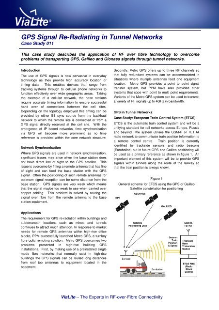
<strong>GPS</strong> <strong>Signal</strong> <strong>Re</strong>-<strong>Radiat<strong>in</strong>g</strong> <strong>in</strong> <strong>Tunnel</strong> <strong>Networks</strong>Case Study 011This case study describes the application of RF over fibre technology to overcomeproblems of transport<strong>in</strong>g <strong>GPS</strong>, Galileo and Glonass signals through tunnel networks.IntroductionThe use of <strong>GPS</strong> signals is now pervasive <strong>in</strong> everydaytechnology as they provide high accuracy location ortim<strong>in</strong>g data. This enables devices that range fromtrack<strong>in</strong>g systems through to cellular phone networks tofunction effectively over wide geographic areas. Tak<strong>in</strong>gthe example of a cellular network, the base stationsrequire accurate tim<strong>in</strong>g <strong>in</strong>formation to ensure successfulhand over of connections between the cell sites.Depend<strong>in</strong>g on the topology employed this tim<strong>in</strong>g can beprovided by either E1 sync source from the backhaulnetwork to which the remote site is connected or from a<strong>GPS</strong> signal directly received at the cell site. With theemergence of IP based networks, time synchronisationvia <strong>GPS</strong> will become more prom<strong>in</strong>ent as no timereference is provided with<strong>in</strong> the core network structure.Network SynchronisationWhere <strong>GPS</strong> signals are used <strong>in</strong> network synchronisation,significant issues may arise when the base station doesnot have direct l<strong>in</strong>e of sight to the <strong>GPS</strong> satellite. Thisissue is overcome by fitt<strong>in</strong>g a remote antenna that has l<strong>in</strong>eof sight and can feed the base station with the <strong>GPS</strong>signal. Often the position<strong>in</strong>g of such remote antennas foroptimum signal reception can be some distance from thebase station. <strong>GPS</strong> signals are very weak which meansthat the signal maybe too weak to use when carried overcopper cabl<strong>in</strong>g. This problem is solved by rout<strong>in</strong>g thesignal over fibre from the remote antenna to the basestation equipment.Secondly, Metro <strong>GPS</strong> offers up to three RF channels sothat fully redundant systems can be accommodated <strong>in</strong>situations where multiple antennas feed one equipmentlocation. Metro <strong>GPS</strong> provides a po<strong>in</strong>t to po<strong>in</strong>t signaltransfer system, but PPM have also provided othersystems that cope with po<strong>in</strong>t to multi po<strong>in</strong>t requirements.Variants of the Metro <strong>GPS</strong> system can be used to transmita variety of RF signals up to 4GHz <strong>in</strong> bandwidth.<strong>GPS</strong> <strong>in</strong> <strong>Tunnel</strong> <strong>Networks</strong>:Case Study: European Tra<strong>in</strong> Control System (ETCS)ETCS is the automatic tra<strong>in</strong> control system and will be aunify<strong>in</strong>g standard for rail networks across Europe, Russiaand beyond. The system utilises the GSM-R or TETRAradio network to communicate tra<strong>in</strong> position <strong>in</strong>formation toa remote control centre. Tra<strong>in</strong> position is currentlyidentified by trackside sensors and radio beacons(Eurobalise) but <strong>in</strong> future <strong>GPS</strong> and Galileo position<strong>in</strong>g willbe used as a primary reference as shown <strong>in</strong> figure 1. Animportant element of this system will be to provide <strong>GPS</strong>signals with<strong>in</strong> tunnels along the route of the railway sothat the tra<strong>in</strong> position is always known.<strong>GPS</strong>Figure 1General scheme for ETCS us<strong>in</strong>g the <strong>GPS</strong> or GalileoSatellite constellation for position<strong>in</strong>gGLONASSGALILEOApplicationsThe requirement for <strong>GPS</strong> re-radiation with<strong>in</strong> build<strong>in</strong>gs andsubterranean locations such as m<strong>in</strong>es and tunnelscont<strong>in</strong>ues to attract much attention. In response to marketneeds for remote <strong>GPS</strong> antennas with<strong>in</strong> high-rise officeblocks, PPM successfully launched Metro <strong>GPS</strong>, a turnkeyfibre optic remot<strong>in</strong>g solution. Metro <strong>GPS</strong> overcomes twoproblems presented <strong>in</strong> high-rise build<strong>in</strong>g <strong>GPS</strong><strong>in</strong>stallations. First, by mak<strong>in</strong>g use of a pre<strong>in</strong>stalled s<strong>in</strong>glemode fibre networks that normally exist <strong>in</strong> high-risebuild<strong>in</strong>gs the <strong>GPS</strong> signals can be routed long distancesfrom roof top antennas to equipment located <strong>in</strong> thebasement.SatellitePosition<strong>in</strong>g DataData onTra<strong>in</strong>Position& SpeedGSM-R /TETRATracksideBaseTransceiverStationETCS RBC(RadioBlockCentre)<strong>ViaLite</strong> – The Experts <strong>in</strong> RF-over-Fibre Connectivity
This creates problems for the weak <strong>GPS</strong> signals due tothe distances <strong>in</strong>volved. PPM has developed an optical reradiationsystem to overcome this problemFor the ETCS project PPM designed and manufacturedthe fibre optic head-end shown schematically <strong>in</strong> Figure 2.The electrical signal is converted <strong>in</strong>to an optical signalwhich is coupled <strong>in</strong>to a passive optical splitter thatproduces a customer def<strong>in</strong>ed number of optical feeds fordistribution to the nodes <strong>in</strong> the tunnel. In this particularcase both primary and secondary <strong>GPS</strong> (RF) feeds wereused for redundancy purposes to ma<strong>in</strong>ta<strong>in</strong> full signal<strong>in</strong>tegrity.Figure 2Schematic of Fibre Optic <strong>GPS</strong> Distribution Head-EndThis technique enables <strong>GPS</strong> extension <strong>in</strong>to the 1150mtunnel without any appreciable degradation to re-radiatorperformance. Figure 4 shows a representation of thedeployed multiple fibre channel po<strong>in</strong>t-to-multipo<strong>in</strong>tdistribution used by the rail operator.Figure 4Deployment used by European rail operator, show<strong>in</strong>g the<strong>GPS</strong> head-end outside the tunnel and receiv<strong>in</strong>g nodesspaced at 150 metres with<strong>in</strong> the tunnel.CoaxialCableElectro-Optical150 metersPrimaryRXRX<strong>GPS</strong> AntennasOpticalSplitterRXSecondaryRXPrimary RF FeedFibre Optic TxModulePrimaryFibreChannelsSecondary RF FeedFibre Optic TxModuleSecondaryFibreChannelsPPM Fibre Optic Head EndOpticalSplitterEach fibre channel feeds <strong>GPS</strong> signals over s<strong>in</strong>gle modefibre optic cable to a <strong>GPS</strong> receiv<strong>in</strong>g node (Rx) shownschematically <strong>in</strong> Figure 3. The receive nodes are located<strong>in</strong>side the tunnel and spaced every 150 metres apart. Ateach receiver node, the <strong>GPS</strong> signal is converted back <strong>in</strong>toan electrical signal before be<strong>in</strong>g fed to <strong>GPS</strong> antennae forre-radiation with<strong>in</strong> the tunnelThe fibre optic system outl<strong>in</strong>ed <strong>in</strong> this case study providesa transport platform that enables extended reach <strong>in</strong>totunnels, and can typically be deployed <strong>in</strong> tunnels over30km <strong>in</strong> length. The po<strong>in</strong>t-to-multipo<strong>in</strong>t configuration hasa high level of redundancy already designed <strong>in</strong>to thetransmission fabric. The head-end hardware comprises astandard outdoor enclosure (IP65 rated & NEMA 13)populated with redundant converters and fibre opticsplitters and distribution. Each re-radiation stage ishoused <strong>in</strong> a standard enclosure (IP66 rated, NEMA 13rated) that feed re-radiat<strong>in</strong>g antennae. This designprovides a primary and secondary path for the <strong>GPS</strong>signals which are both <strong>in</strong> operation at all times.Figure 3Schematic of Fibre Optic <strong>GPS</strong> <strong>Re</strong>ceiver Node (as used <strong>in</strong>a Po<strong>in</strong>t-to-Multipo<strong>in</strong>t Install)PrimaryFibreChannelFibre Optic RxModule<strong>GPS</strong> <strong>Re</strong>-RadiatorsConclusionsThis case study has described the pr<strong>in</strong>ciple of <strong>GPS</strong>transmission over fibre and some of the large number ofapplications that benefit from us<strong>in</strong>g this technology. Theexample of the <strong>ViaLite</strong> Metro <strong>GPS</strong> product is given for use<strong>in</strong> build<strong>in</strong>g distribution, and the case of the European railoperator that required <strong>GPS</strong> distribution through tunnelnetworks has been given <strong>in</strong> some detail.SecondaryFibreChannelFibre Optic RxModulePPM Fibre Optic <strong>Re</strong>ceiver NodeThe follow<strong>in</strong>g l<strong>in</strong>ks provide more general <strong>in</strong>formation onthis topic.http://en.wikipedia.org/wiki/European_Tra<strong>in</strong>_Control_Systemhttp://www.ertms.comhttp://www.uic.asso.fr/uic/spip.php?rubrique850Pulse Power & Measurement Ltd, 65 Shrivenham Hundred Bus<strong>in</strong>ess Park, Watchfield, Sw<strong>in</strong>don, Wiltshire SN6 8TY, UKTel: +44 (0)1793 784389 Fax: +44 (0)1793 784391 Email: sales@ppm.co.uk Web: www.vialite.com