Drive Solutions for the Global Paper Industry - Tmeic.com
Drive Solutions for the Global Paper Industry - Tmeic.com
Drive Solutions for the Global Paper Industry - Tmeic.com

Create successful ePaper yourself
Turn your PDF publications into a flip-book with our unique Google optimized e-Paper software.
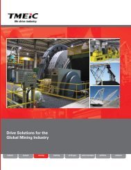
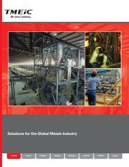
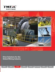
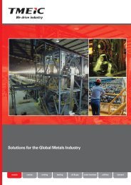
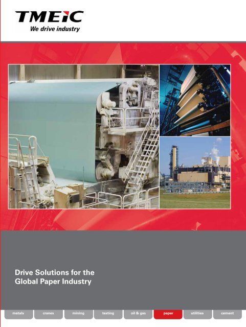
<strong>Drive</strong> <strong>Solutions</strong> <strong>for</strong> <strong>the</strong><strong>Global</strong> <strong>Paper</strong> <strong>Industry</strong>metals cranesmining testing oil & gas paper utilities cement
Organization of DocumentTMEIC engineers design, test, and <strong>com</strong>mission <strong>com</strong>plete coordinated drive systems <strong>for</strong> paper machines that includefan pumps, dryers, calenders, winders, and coaters. This document provides an overview of <strong>the</strong> engineering processesand technology used in <strong>the</strong>se systems. The chart below illustrates <strong>the</strong>se engineering processes and technology.A Comprehensive Engineering ProcessA smooth machine startup in <strong>the</strong> mill depends on a well-planned and executed engineering process. Starting with <strong>the</strong>system proposal and specification, TMEIC’s application engineers manage <strong>the</strong> entire project through <strong>com</strong>missioning.This critical engineering process is illustrated below and detailed in <strong>the</strong> Project Engineering section. Icons indicatewhere <strong>the</strong> various teams of engineers in <strong>the</strong> mill, factory, and field service organizations are involved in <strong>the</strong> project.TechnicalProposalSpecificationCustomer TeamField TeamSystem FunctionalSpecification+ Customer ReviewDetailedSoftwareDesignDetailedHardwareDesignFactoryAcceptanceTestSystemComponentProcurementSystemCommis-sioningSystemMaintenanceandService10Factory TeamTraining TeamProject Engineering ProcessA Flexible System ArchitectureThe drive system architecture uses a master PLC controller to coordinate all <strong>the</strong> networked drives, which can be ofdifferent types, and to <strong>com</strong>municate with <strong>the</strong> operator interfaces, input/output devices, and <strong>the</strong> mill’s distributedcontrol system (DCS).TMEIC has adopted industry standards to simplify<strong>the</strong> configuration and integration of <strong>com</strong>plexcontrol systems <strong>for</strong> your paper machine:• VME cards and rack <strong>for</strong> <strong>the</strong> master controller,allowing seamless integration of third-partysystemsMaster Controller• Profibus ® and E<strong>the</strong>rnet ® <strong>com</strong>municationsbetween <strong>the</strong> drives, controller, operatorinterfaces, and plant control, providing highspeed<strong>com</strong>munication, and low-cost, standardspare parts availability.+- ACTM-10TM-DCTM-10e2• Windows ® -based configuration tools, familiarto all users, <strong>for</strong> all system <strong>com</strong>ponents.
TMEIC’s <strong>Paper</strong> <strong>Industry</strong> TeamDedicated <strong>Paper</strong> Engineering TeamThe paper engineering team is dedicated to<strong>the</strong> paper industry and gained <strong>the</strong>ir experienceworking in field service with mill techniciansand mechanical suppliers. This background,coupled with state-of-<strong>the</strong>-art technology,enables TMEIC to consistently meet <strong>the</strong>demanding requirements of <strong>the</strong> paper industry.Technical Proposal SpecificationDuring your project planning stage,experienced paper industry drive systemapplication engineers prepare a technicalproposal that includes:• Customized system architecture <strong>for</strong>your project• Detailed equipment specifications• Formal bid documentationOur application engineers are highlyqualified <strong>for</strong> this proposal work, andseveral of <strong>the</strong>m have 30+ years of paperindustry experience. In addition, <strong>the</strong>yare actively involved in paper industrytechnical organizations, where <strong>the</strong>y authorpapers and conduct training seminars:• TAPPI – Technical Association of <strong>the</strong>Pulp & <strong>Paper</strong> <strong>Industry</strong>• IEEE – Institute of Electrical &Electronic Engineers• PAPTEC – Pulp & <strong>Paper</strong> TechnicalAssociation of Canada• APPITA – Technical Association of<strong>the</strong> Australian and NewZealand Pulp and <strong>Paper</strong><strong>Industry</strong>, Inc.• IARPMA – Indian Agro and Recycled<strong>Paper</strong> Mills Association• ABTCP – Associagão BrasileriaTécnica de CellulosedePapel
System Functional SpecificationAfter project approval, our applicationengineers prepare a technicalspecification that includes:• Customized system architecturewith an electro-mechanical one-linediagram <strong>for</strong> your project as shown in<strong>the</strong> illustration• Detailed equipment specification:- <strong>Drive</strong>s- Master Control- I/O devices and modules- Motors• Complete operational description.To ensure we meet yourrequirements, a thorough reviewof <strong>the</strong> specification is held at yourfacility with your project team.TDC BusISBusM1 st WireReturnCurrent RegSpeed LimitLAN I/FMTDandyRollCurrent RegSpd/Drp RegLAN I/FMT4 th WireCurrent RegSpd/Drp RegLAN I/FTM1 st WireCouchCurrent RegSpeed LimitLAN I/FTM1 st WireWire TurnCurrent RegSpeed RegLAN I/FDetailed Hardware/Software Design &ProcurementBased on <strong>the</strong> functional specification,<strong>the</strong> project engineering team proceedswith three main tasks:• Software DesignMaster Controller softwaredesigned <strong>for</strong> ease of maintainability.The adjacent illustration shows atypical function block diagram withlogic in relay <strong>for</strong>mat.• Hardware DesignAll equipment is specified per<strong>the</strong> project requirements, anda <strong>com</strong>plete set of elementarydiagrams, layout and outlinedrawings are created.• Component ProcurementWe work with our parent <strong>com</strong>paniesto source <strong>the</strong> most cost effectivesystem <strong>com</strong>ponents <strong>for</strong> yourapplication.
Enabling Technology <strong>for</strong> Process Simulation in a Factory System TestReal-World/Mill EnvironmentFactory Test SimulationLocal Area Networks<strong>Drive</strong> ControllerPower BridgeMMotorLoadLocal Area Networks<strong>Drive</strong> ControllerM LoadDigital MotorSimulatorDigital LoadSimulatorPowerPowerPower<strong>Drive</strong> CabinetController,Power Bridge,and MotorLegacy and new TMEIC AC and DC <strong>Drive</strong>sIncluding TMdrive-10e2, Innovation AC/DC and AC/DC2000MModelLoadModelIntertia K 1 dN/dtFriction K 2 NWindage K 3 N 2In <strong>the</strong> mill, AC and DC <strong>Drive</strong>s Control MotorSpeed and Mechanical LoadEach AC drive has a controller with I/O and a gatedriver, which controls <strong>the</strong> power IGBTs in <strong>the</strong> powerbridge. The power bridge generates <strong>the</strong> adjustablefrequency AC voltage supply to <strong>the</strong> three-phase motor,controlling its speed and torque.In <strong>the</strong> case of a DC drive, <strong>the</strong> power thyristor-basedpower bridge converts <strong>the</strong> AC power to a variable DCvoltage, which is applied to <strong>the</strong> motor armature. Thiscontrols <strong>the</strong> DC motor’s speed and torque.In <strong>the</strong> Factory System Test, <strong>the</strong> <strong>Drive</strong>s Control aMotor and Mechanical SimulatorEach AC/DC drive in <strong>the</strong> system has its own digital motorsimulator based on a dynamic ma<strong>the</strong>matical model.The drives control <strong>the</strong> simulators, not real motors.All drive simulators are networked with <strong>the</strong> mastercontroller and operator stations to test <strong>the</strong> entire systemin real time. Starts, stops, running modes, responseto manual inputs, LAN continuity, control interaction,and drive configuration are all validated. This uniquecapability allows <strong>the</strong> entire team to obtain an intimateunderstanding of <strong>the</strong> system prior to <strong>com</strong>missioning,ensuring a smooth, on-time startup <strong>for</strong> your project.“Once <strong>the</strong> design engineer has <strong>com</strong>pleted <strong>the</strong> system software <strong>for</strong> a paper mill drive system, it is imperativethat <strong>the</strong> software be tested under realistic conditions prior to <strong>the</strong> <strong>com</strong>missioning at <strong>the</strong> site. The software testshould consist of a simulation of <strong>the</strong> process, with inputs, outputs, operator displays, HMIs, maintenancesoftware tools, and any <strong>com</strong>munication data links. A motor/load simulator included in each drive eliminates<strong>the</strong> need <strong>for</strong> specially designed software just <strong>for</strong> <strong>the</strong> simulation. The user’s project, maintenance, and operatorpersonnel should all participate in this system simulation (Customer Acceptance Test). TMEIC realizes <strong>the</strong>importance of this type of a <strong>com</strong>plete simulation and endeavors to produce a thoroughly tested product on eachpaper mill drive in order to minimize startup problems.- Bill CampbellSenior <strong>Drive</strong>s & Control EngineerManufacturing Technology Center, International <strong>Paper</strong>“
System CommissioningIn <strong>the</strong> <strong>com</strong>missioning phase of <strong>the</strong> project, <strong>the</strong> TMEIC team includes<strong>the</strong> local field engineers you know and trust, alongside <strong>the</strong> factoryengineer who designed and tested <strong>the</strong> system. This overlap ofteams between <strong>the</strong> factory and <strong>the</strong> mill ensures a smooth and onschedulestartup.The local service person is part of <strong>the</strong> project team and participatesin <strong>the</strong> factory system test to be<strong>com</strong>e familiar with <strong>the</strong> system. He<strong>the</strong>n takes responsibility <strong>for</strong> startup and <strong>com</strong>missioning, and isavailable later if any service is required at <strong>the</strong> mill. The availablesupport <strong>for</strong> <strong>com</strong>missioning includes:• TMEIC factory control engineers• TMEIC factory service engineers• Remote diagnostics service• Local strategic service partnerThe <strong>com</strong>missioning phases are shown below:1Oversee Installationof ElectricalEquipment:- Motors- <strong>Drive</strong>s- Master Control- Cabling & Wiring2Check out allWiring &CommunicationLinks, Load allSoftware, andCommission <strong>the</strong><strong>Drive</strong>s and Motors3<strong>Paper</strong> MachineSection ControlCommissioning4<strong>Paper</strong> MachineControl CommissioningCommissioningTeams InvolvedCommissioning Time LineTMEIC offers a single source <strong>for</strong> installation supervision and <strong>com</strong>missioning. Phases 2, 3, and 4 are <strong>com</strong>pressed by:• The exhaustive factory acceptance test that includes all drive controllers, master controller, and <strong>com</strong>municationlinks• Time-saving <strong>com</strong>missioning and drive tune-up Wizards• Training and familiarization of <strong>the</strong> entire team with <strong>the</strong> system at <strong>the</strong> factoryComplete and Detailed <strong>Drive</strong> System DocumentationAlong with <strong>the</strong> hardware and software, TMEIC delivers <strong>com</strong>plete systemdocumentation:• An electronic instruction book with all <strong>the</strong> prints on CD with a hyperlinkindex• System configuration on CD and a hard-copy <strong>for</strong>m• Detailed system manual• Re<strong>com</strong>mended wiring and grounding procedures• Renewal parts list• Standard third-party vendor documentation
<strong>Global</strong> Customer Support NetworkSystem Maintenance and ServiceComprehensive technical service is provided by our Customer Support Organization, staffed by TMEIC serviceengineers with offices and spare parts depots across <strong>the</strong> globe.European SpareParts DepotKrakowLondonFrankfurtTMEIC CorporationHeadquartersRoanoke, VATMEIC HoustonBeijingSeoulTokyoShanghaiHyderabadHong KongTokyo, JapanTMEIC Head Office& FactoryKuala LampurSingaporeJakartaRio de JanieroSao PauloBuenos AiresSantiagoBrisbanePerthSydneyMelbourneIn North and South AmericaCustomers are supported by <strong>the</strong> TMEICCorporation service personnel, design engineersand Spare Parts Depot in Virginia, and <strong>the</strong> TMEICFactory in Japan.In EuropeTMEIC service engineers service all drive systemsin Europe, supported by <strong>the</strong> European TMEICSpare Parts Depot.In Asia and <strong>the</strong> Pacific RimTMEIC services drive systems throughout China,India and <strong>the</strong> Pacific Rim, supported by multipleField Engineers, Spare Parts Depots, and <strong>the</strong>TMEIC factory in Japan.Remote <strong>Drive</strong> DiagnosticsTMEIC Corporation supports drive customersthrough <strong>the</strong> Remote Connectivity Module (RCM),a remote diagnostic service link with <strong>the</strong> TMEICdesign and service engineers in Roanoke, Virginia.The RCM enables seamless integration betweenyour drives and our engineers.Remote System DiagnosticsTMEIC’s remote system diagnostics tool, includedin level 1 software, offers a quick path to problemresolution. System faults are automaticallyidentified, and provide an integrated view ofproduct, process and system in<strong>for</strong>mation.TMEIC design and service engineers in Roanoke,Virginia, can analyze <strong>the</strong> data and provide steps<strong>for</strong> resolution.Remote Diagnostic Service reduces Mean Time To Repair (MTTR)Remote Connectivity Module (RCM) offers protection <strong>for</strong> your investment, by reducing downtime, lowering repaircosts and providing peace of mind. RCM requires an internet connection between your plant and TMEIC Corporation<strong>for</strong> retrieval of fault logs and files to diagnose drive issues.Features• Reduced downtime andMean-Time-to-Repair• Secured connection• Fault Upload UtilityBenefitsQuick support saves thousands of $ in lost productionTMEIC engineers can quickly connect to <strong>the</strong> drive or system and diagnosemany issues in a matter of minutes.Customer-controlled accessAll remote activity is conducted with permission of <strong>the</strong> customer. <strong>Drive</strong>start/stop is not permitted remotely.Proprietary Fault Upload SoftwareHistorical drive faults are identified; TMEIC design and service engineerscan analyze <strong>the</strong> issue resulting in <strong>the</strong> fault and provide a solution.
Low Voltage System <strong>Drive</strong> OverviewTMdrive ® -10e2The family of low voltage AC system drives hasan integral DC bus structure with a wide variety ofinverters (DC to AC) and converters (AC to DC) tomatch virtually any application in <strong>the</strong> paper industry.• 400, 460, 575, or 690 volt operation• Motor power up to 1,949 kW• Regenerative converter optionDraw-Out Style InvertersFor applications up to 193 kW (249 hp), draw-out styleinverters are available in a very <strong>com</strong>pact package.Draw-out inverters are mounted on heavy-duty slides withstaggered dc bus connectors on <strong>the</strong> back that connect with<strong>the</strong> bus when slid into <strong>the</strong> cabinet.Motor cables are terminated at a <strong>com</strong>mon terminal blockin <strong>the</strong> bottom of <strong>the</strong> cabinet.CondenserIGBT powerswitchesChillPlateHeat Pipe Cooling TechnologyThe use of heat pipe technology provides a dramaticadvance in power bridge cooling, including asignificant reduction in <strong>the</strong> footprint of <strong>the</strong> powerbridge, and fewer fans lower <strong>the</strong> audible noise.The Thermal Cycle12Condensate to VaporIGBT’s are mounted to <strong>the</strong> multi-channeled chillplate which cools <strong>the</strong>m. Heat generated by <strong>the</strong>IGBTs vaporizes <strong>the</strong> refrigerant, moving it upwardsthrough <strong>the</strong> chill plate to <strong>the</strong> finned condensingunit.Vapor To CondensateCooling air is pulled up through <strong>the</strong> IGBTs and <strong>the</strong>condensing unit, and cools <strong>the</strong> refrigerant, whichcondenses back to liquid.3Return of CondensateThe condensed refrigerant returns to <strong>the</strong> bottomof <strong>the</strong> chill plate to start <strong>the</strong> <strong>the</strong>rmal cycle overagain.
TMdrive-10e2 Operator InterfacesCabinet Enclosure DisplaysThree-digit display alternates between speed and currentwhile running, or a fault code when <strong>the</strong>re is an error.Standard DisplayLEDs give a quick indication of <strong>the</strong> statusof <strong>the</strong> unit.LED indicationReady On when <strong>the</strong> unit is ready torunRunningOn when <strong>the</strong> unit is runningAlarm/FaultBlinking LED indicates alarmcondition, while solid LEDindicates a faultRJ-45 E<strong>the</strong>rnet port is used <strong>for</strong>local tool connectionInterlock buttondisables <strong>the</strong> driveDC BusOn when DC Bus isDischargedOptional Enhanced KeypadNavigationAllows adjustment of drive parametersfrom <strong>the</strong> front of <strong>the</strong> equipmentControlsAllow <strong>the</strong> equipment to be controlledin local mode from <strong>the</strong> front of <strong>the</strong>equipment.• Reset faults, reverse direction, inc./dec.speed, jog, run and stop are available.• Switch to local mode to allow operationat this control panel.Optional analog meters can be supplied in addition to ei<strong>the</strong>r <strong>the</strong> standard or enhanceddisplay. Standard inverter I/O includes meter driver outputs that are +/- 10 V with 10-bitresolution. For cabinet style equipment, four meters are provided. For draw-out style,two meters are provided <strong>for</strong> each inverter.Draw-out Enclosure DisplaysLEDs give a quick indication of <strong>the</strong> statusof <strong>the</strong> unit.LED indicationDC Bus On when <strong>the</strong> DC Busis dischargedReady On when <strong>the</strong> unit is ready torunRunning On when <strong>the</strong> unit is runningAlarm/Fault Blinking LED indicates alarmcondition, while solid LEDindicates a faultDC Bus On when DC Bus isdischarged
TMdrive ® -DC System <strong>Drive</strong> OverviewThe TMdrive-DC family of system drives share numerous <strong>com</strong>ponents with<strong>the</strong> TMdrive-10e2 AC products and are <strong>com</strong>posed of several frames offered inany <strong>com</strong>bination of four <strong>for</strong>m factors (digital front end (DFE) control retrofits,frame assemblies, module assemblies, <strong>com</strong>plete cabinet assemblies).This flexibility of <strong>for</strong>m factors and <strong>com</strong>monality with <strong>the</strong> TMdrive-10e2 ACproducts suits <strong>the</strong> current modernization project trends in <strong>the</strong> paper industry:• Digital Front End (DFE) control retrofits on larger DC drives, saving<strong>the</strong> expense of replacing <strong>the</strong> existing power bridge and motor.• Selected DC drive frame upgrades to address incremental powerrequirements.• Frequent use of both DC and AC drive technology in projects.Featuring Flexible Mechanical DesignTMdrive-DC’s flexibility in packaging allows it to meet virtually any new or retrofit application. Three of <strong>the</strong> more<strong>com</strong>mon applications are illustrated below.Legacy DC <strong>Drive</strong>Modernized TM-DC <strong>Drive</strong>Hardwired I/O Interface<strong>Drive</strong> reference, feedbackand status signals hardwiredwith rest of <strong>the</strong> controlsystemAnalog RegulatorCurrent and speedregulators built fromanalog <strong>com</strong>ponentsTMdrive-DCDFEDFE Digital Front EndRetrofit legacy drive control withTMdrive-DC digital front end andcontrols, preserving existing powerbridge, auxiliary power <strong>com</strong>ponentsin panel, cabinet, motor cabling, andmotorTMdrive-DCTMdrive-DC ModuleAssemblyRetrofit legacy drivecontrol and panel withTM-DC DFE controls,new power bridge, andpanel <strong>com</strong>ponents,preserving exisitingcabinet, motor cabling,and motorTMdrive-DC& CabinetPower BridgeOriginal DC sourcein <strong>the</strong> DC <strong>Drive</strong>Hardware Based SequencerSequencing functionshardwired on TTL or relaysTMdrive-DC and CabinetRetrifit entire legacy drive withTMdrive-DC drive including:- Controls- Power bridge- Panel- Cabinetperserving existing motorcabling and motor
nv ControllerThe nvController is a high-per<strong>for</strong>mance, large capacity controller designed <strong>for</strong> industrial applications. The capabilitiesinclude sequencing, coordinated motor speed control, and continuous control. The main nvController features are:Controller• High-speed processing, 20 ns per basic instructionword, 100 ns per floating decimal point• Control cycle 0.5 msec to 1000 msec• Program capacity 256 K steps• Data capacity 256 K words, 16,384 16-bit I/O words• ECC (Error Check and Correction) memory• Multi-controller <strong>com</strong>patible, up to three CPUs perchassis• Multi-scan tasks, high-speed scan as fast as 0.5 msecper program• Total of 18 interrupt TasksCommunication• E<strong>the</strong>rnet <strong>Global</strong> Data (EGD)• TC-net 100 control LAN Links <strong>the</strong> controllers:- Star type optical network- 2 km between nodes, overall length 12 km- Transmission rate 100 Mbps; 1 millisecondupdate- Dual transmission cable option <strong>for</strong> redundancy• Field mounted I/O modules and <strong>the</strong> drives are onTC-net I/O, an electro-optical LAN:- Loop type network- Transmission rate 100 Mbps- Overall length 100 m (electrical), 4 km (optical)nVController, up tothree per chassisTC-net 100E<strong>the</strong>rnet 1GbpsPower supplyUnused spacein chassisInput/Output LAN TC-net I/O LoopControl LAN TC-net 100 Fiber-opticInput/Output LAN TC-net I/O Loop returnController Configuration ToolTools <strong>for</strong> configuring <strong>the</strong> controller are contained in <strong>the</strong>engineering Tool software, TMEIC’s innovative selectionof software tools <strong>for</strong> configuring <strong>the</strong> system. These toolshave <strong>the</strong> same “look and feel” with similar screens anduser actions, thus simplifying <strong>the</strong> control engineer’sprogramming task.The Engineering Tool controller software offers allfour IEC81131.3 standard logic control programminglanguages:• RLD Relay Ladder Diagrams• FBD Function Block Diagrams• SFC Sequential Function Charts• ST Structured TextThe TMdrive-Navigator is used to configure andmonitor <strong>the</strong> drives. This software provides searchtechnology linking signal lists, block diagrams,product documentation, change history, and usernotes. High speed data is automatically captured andsaved in <strong>the</strong> event of a drive fault, or on user triggerconditions. High resolution real-time trending showsand <strong>com</strong>pares multiple drive variables.Live block diagrams provide real-time graphical viewsof <strong>the</strong> drive functions, and functions can be configureddirectly from <strong>the</strong> graphical view.
Innovation Series ControllerThe VME controller rack contains <strong>the</strong> power supply, controller board, and spare slots <strong>for</strong> various <strong>com</strong>munication cards.Open architecture rackcontains controller andLAN interface circuitboardsThird-party interfaces to Profibus-DP andControlNet local area networksVME Version of Innovation Series ControllerController FeaturesLAN OptionsAll controllers have connectivity to a wide range of LocalArea Networks and I/O device networks:• All TMEIC and GE drives, I/O, HMIs• Allen-Bradley PLCs, ControlNet , DH+, and PanelView• Siemens PLCs via Profibus• DeltaV controller via ProfibusSpecial Permissive FunctionsControl system diagnostics uses function blocks andoperator interface tools (Diagnose)BenefitsSeamlessly Integrates with O<strong>the</strong>r Control SystemsLAN connectivity options provide seamlessintegration with <strong>the</strong> rest of <strong>the</strong> mill, regardless of <strong>the</strong>legacy and third-party equipment already installed.Ei<strong>the</strong>r E<strong>the</strong>rnet or ISBus can be used to provideconfiguration/diagnostic support with <strong>the</strong> Windowsbasedtoolbox.Reduces DowntimeQuickly identify permissive faults on <strong>the</strong> machinefrom <strong>the</strong> operator interface so repairs can be madeMulti-TaskingPreemptive, multi-tasking controller allowing functionswith various scan rates to run concurrentlyPer<strong>for</strong>ms More ControlPer<strong>for</strong>ms high-speed control functions toge<strong>the</strong>rwith low-speed functions without overloading <strong>the</strong>controller
Operator and Technician InterfacesPanel-Mounted Local Operator Interface and HMI Technician InterfaceFeaturesPanel-Mounted Touch ScreenMounted close to <strong>the</strong> machinery, <strong>the</strong> touch screen iseasy to use and fast-acting.Machine Permissive DiagnosticsThe Boolean logic block with diagnostics indicates inred <strong>the</strong> contact preventing <strong>the</strong> machine sequencing.BenefitsConvenient, Reliable Machine Control PanelPanel-mounted close to <strong>the</strong> machine, <strong>the</strong> touch screenprovides an intuitive display and hardwired-likecontrol action allowing machine jogging. The ruggedindustrial <strong>com</strong>puter stands up to <strong>the</strong> mill environment.Faster Operator ResponseReduces <strong>the</strong> time to resolve permissive and/oroperator training issues.HMI Trend RecorderHigh-speed real-time and historic data from <strong>the</strong> controlsystem and drives is available on <strong>the</strong> HMI trend screen.Convenient <strong>Drive</strong> and Machine DiagnosticsThe high-resolution HMI screen trends live data from<strong>the</strong> controller, and data from drive capture buffers atrates up to 0.5 ms, <strong>for</strong> convenient drive and machineper<strong>for</strong>mance analysis, and <strong>for</strong> diagnostics.
What Differentiates TMEIC’s Operator Touch Screen?TMEIC differentiates its touch screenfrom <strong>the</strong> <strong>com</strong>petition by providing anintuitive screen design and fast-actingresponse to operator inputs by:• Bringing <strong>the</strong> operator into <strong>the</strong> screendesign process to ensure a goodlayout and simple screen navigation• Applying a special E<strong>the</strong>rnet<strong>com</strong>munication protocol optimized<strong>for</strong> <strong>the</strong> maximum data transfer and<strong>the</strong> lowest turnaround time at eachendThis <strong>com</strong>bination of technology andengineering practices separates ouroffering from <strong>the</strong> o<strong>the</strong>rs.Operators Design <strong>the</strong> Best Touch Screen LayoutsGood touch screen design is achieved with an iterative process that includes <strong>the</strong> operators in each step. The designprocess provides three opportunities <strong>for</strong> <strong>the</strong> operator to participate in <strong>the</strong> screen design:• At <strong>the</strong> beginning, during review of <strong>the</strong> system specification• In Virginia, during <strong>the</strong> factory test, be<strong>for</strong>e <strong>the</strong> pressure of <strong>the</strong> mill startup begins• In <strong>the</strong> mill during <strong>com</strong>missioning, to <strong>com</strong>ment on <strong>the</strong> operation of <strong>the</strong> actual panel and systemS p e c ific a tio nOperator reveiws <strong>the</strong>panel requirementsand gives feedbackOperator sees and works <strong>the</strong>actual panel in <strong>the</strong> factory systemtest, and gives feedbackOperator works <strong>the</strong> actual panelrunning <strong>the</strong> paper machine in <strong>the</strong>mill, and can make changesProposalSpecificationSoftwareFactoryTestCommissioningServiceHardwareProcureThree Operator Inputs to <strong>the</strong> Screen Design
The HMI, <strong>the</strong> Technician and Maintenance InterfaceThe HMI provides technicians andmaintenance personnel with aclear window into <strong>the</strong> operation of<strong>the</strong> drive system, displaying:• All real-time machine controland drive data• Alarms and operator control• Real-time and historic trending• Permissive diagnostic displays• System Overview providesaccess to <strong>the</strong> control programfiles• Toolbox software <strong>for</strong> drivesystem configuration• <strong>Drive</strong> tuning screensThe HMI Super Screen (opposite) is an operatoroverview of <strong>the</strong> drive system, with control by touchscreen or mouse, and color-coded <strong>for</strong> fast operatorrecognition. Real-time data is listed <strong>for</strong> each drive:• <strong>Drive</strong> run mode with active regulator type – Speed,Torque, Draw• Operator’s setpoint value, and setpoint feedbackfrom <strong>the</strong> drive• Speed feedback derived from a tachometer signalor sensorless algorithm• Load % in terms of torque• Buttons to call up trend data, and to reset a drive• <strong>Drive</strong> fault in<strong>for</strong>mationData analysis is simplified using <strong>the</strong> Trend Recordershown on <strong>the</strong> right, which displays real-time andhistorical data. Multiple signal traces are selectedby dragging and dropping variables from <strong>the</strong> blockdiagram view. The recorder shows:• Live data from <strong>the</strong> controller, trended as fast asevery 20 ms• High-speed data from capture buffers in <strong>the</strong> drive,trended every 1 ms or faster• Movable cursors to read out values of <strong>the</strong> trendsshown at <strong>the</strong> bottom of <strong>the</strong> screen
System ModernizationWhen it’s time to modernize your drive system, who better to trust than <strong>the</strong> people who built <strong>the</strong> original system? TMEIChas <strong>the</strong> technology and project engineering team to provide a smooth migration path <strong>for</strong>ward. The following pageschronicle <strong>the</strong> system architectures over <strong>the</strong> years and your options going <strong>for</strong>ward. Please locate your system and explore<strong>the</strong> opportunities <strong>for</strong> modernization.1970’s System ArchitectureHMITouch ScreenMaster Control5Bench Boards6HardwiredoperatordevicesTM-DC Digital Front End(DFE)1TM-DC ModuleAssembly- Hardwired relays- TTL Logic4SiltrolSiltrolSiltrol2TM-10 AC<strong>Drive</strong>Master ControllerMMM3DCS networkinterfaceI/OItem Equipment Notes Benefits<strong>Drive</strong> Modernization1- Modernize your Siltrol drives with <strong>the</strong> TM-DC or TM-10AC drives. The DC modernization can occur at one ofthree levels:2 Digital Front End (DFE) Panel with DFE Completely replace drive3- Both <strong>the</strong> TM-DC and TM-10 drives can becontrolled from I/O or one of several local areanetworks (ISBus, Profibus-DP, DeviceNet,TOSLINE-S20)- Configuration of <strong>the</strong> control is done from <strong>the</strong> ControlSystem Toolbox4 Master Control Modernization- Replace <strong>the</strong> electromechanical relay and TTL logicwith a VME rack-based Innovation Series Controllerand associated I/O- The VME rack allows a wide variety of third-partymodules to interface with virtually any industrial LAN5 Color Touch Screen Operator Interface- Graphical touch screens <strong>for</strong> operator control of <strong>the</strong>drives- Hardwired-like per<strong>for</strong>mance using a high-speedE<strong>the</strong>rnet <strong>com</strong>munications link6 Human Machine Interface (HMI)- Graphical overview of drive system status anddiagnostic in<strong>for</strong>mation- Integral historian provides flight-recorder-likefunctionality- More precise and consistent control with <strong>the</strong> digitalregulators- The local area network interface between <strong>the</strong> drives andmaster control provides <strong>for</strong> a more precise speedreference distribution to <strong>the</strong> drives- With <strong>the</strong> TM-10 and TM-DC sharing <strong>com</strong>mon controlhardware <strong>com</strong>ponents, spare part costs are minimizedin AC-DC hybrid systems- Digital solid state electronics are far more reliable andprecise than electromechanical relay and TTL logic- The open architecture of a VME rack provides aseamless interface with <strong>the</strong> rest of your control system- Vast improvement in flexibility of <strong>the</strong> design, allowing <strong>the</strong>interface to evolve without impacting hardware- Diagnostic data <strong>for</strong> both machine operation and drivestatus- Intuitive interface <strong>for</strong> system status and diagnostic tools- Historian provides powerful insight into machine events
Early 1980’s System ArchitectureHMIDCS networkinterfaceInnovation ControllerTM-DC Digital Front End(DFE)TM-DC ModuleAssembly64I/OCPL or Series Six I/O BusDMC or Series SixMaster Controller15CPL Drop In StationDrop In StationSiltronSiltronSiltron2TM-10 AC<strong>Drive</strong>TouchScreenMMM3Item Equipment Notes Benefits123456<strong>Drive</strong> Modernization- Modernize your Siltron drives with <strong>the</strong> TM-DC or TM-10 AC drives. The DC modernization can occur atone of three levels: Digital Front End (DFE) Panel with DFE Completely replace drive- Both <strong>the</strong> TM-DC and TM-10 drives can be controlledfrom I/O or one of several local area networks (ISBus,Profibus-DP, DeviceNet, TOSLINE-S20)- Control can operate with a digital tachometer orwithout a tachometer- Configuration of <strong>the</strong> control is from <strong>the</strong> ControlSystem ToolboxMaster Control Modernization- Replace <strong>the</strong> dated Series Six and/or DMC with aVME rack-based Innovation Series Controller andassociated I/O- The VME rack allows wide variety of third-partymodules to interface with virtually any industrial localarea network- Controller is programmed in function block languageusing <strong>the</strong> Control System ToolboxColor Touch Screen Operator Interface- Graphical touch screens <strong>for</strong> operator control of <strong>the</strong>drives- Hardwired-like per<strong>for</strong>mance using a high-speedE<strong>the</strong>rnet <strong>com</strong>munications linkHuman Machine Interface (HMI)- Graphical overview of drive system status anddiagnostic in<strong>for</strong>mation- Integral historian provides flight-recorder-likefunctionality- Siltron drives transitioned to AC technology will eliminate<strong>the</strong> periodic expense of DC motor maintenance- <strong>Drive</strong>s modernized with TM-DC controls provide moreprecise control and improved diagnostic data- With <strong>the</strong> TM-10 and TM-DC sharing <strong>com</strong>mon controlhardware <strong>com</strong>ponents, spare part costs are minimized inAC-DC hybrid systems- Open architecture of VME rack provides a seamlessinterface with <strong>the</strong> rest of your control system- The Control System Toolbox provides a <strong>com</strong>monapplication <strong>for</strong> both <strong>the</strong> controller and all of TMEIC’ssystem drives- Vast improvement in flexibility of <strong>the</strong> design, allowing <strong>the</strong>interface to evolve without impacting hardware- Diagnostic data <strong>for</strong> both machine operation and drivestatus- Intuitive interface <strong>for</strong> system status and diagnostic tools- Historian provides powerful insight into machine events
Late 1980’s System ArchitectureDCS networkinterfaceHMI6Innovation ControllerI/ODLAN4Series SixMaster ControllerTM-DC Digital Front End(DFE)TM-DC ModuleAssembly15DC300DC300DC3002TM-10 AC<strong>Drive</strong>TouchScreenMMM3Item Equipment Notes Benefits<strong>Drive</strong> Modernization1- Modernize your DC300 drives with <strong>the</strong> TM-DC or TM-10AC drives. The DC modernization can occur at one ofthree levels:2 Digital Front End (DFE) Panel with DFE Completely replace drive3- Both <strong>the</strong> TM-DC and TM-10 drives can be controlled fromI/O or one of several local area networks (ISBus,Profibus-DP, DeviceNet, TOSLINE-S20)- Control can operate with or without a digital tachometer- Configuration of <strong>the</strong> control is from <strong>the</strong> Control SystemToolbox4 Master Control Modernization- Replace <strong>the</strong> dated Series Six with <strong>the</strong> VME rack-basedInnovation Series Controller and associated I/O- The VME rack allows wide variety of third-party modulesto interface with virtually any industrial local area network- Controller is programmed in function block languageusing <strong>the</strong> Control System Toolbox5 Color Touch Screen Operator Interface- Graphical touch screens <strong>for</strong> operator control of <strong>the</strong> drives- Hardwired-like per<strong>for</strong>mance using a high-speed E<strong>the</strong>rnet<strong>com</strong>munications link6 Human Machine Interface (HMI)- Graphical overview of drive system status and diagnosticin<strong>for</strong>mation- Integral historian provides flight-recorder-like functionality- DC300 drives transitioned to AC technology willeliminate <strong>the</strong> periodic expense of DC motormaintenance- <strong>Drive</strong>s modernized with TM-DC controls providemore precise control and improved diagnostic data- With <strong>the</strong> TM-10 and TM-DC sharing <strong>com</strong>moncontrol hardware <strong>com</strong>ponents, spare part costs areminimized in AC-DC hybrid systems- Open architecture of VME rack provides aseamless interface with <strong>the</strong> rest of your controlsystem- The Control System Toolbox provides a <strong>com</strong>monapplication <strong>for</strong> both <strong>the</strong> controller and all of TMEIC’ssystem drives- Vast improvement in flexibility of <strong>the</strong> design,allowing <strong>the</strong> interface to evolve without impactinghardware- Diagnostic data <strong>for</strong> both machine operation anddrive status- Intuitive interface <strong>for</strong> system status and diagnostictools- Historian provides powerful insight into machineevents
Early 1990’s System ArchitectureInnovation Controller4MM2000HMITM-DC Digital Front End(DFE)TM-DC ModuleAssemblyDCS networkinterfaceI/O6DLAN+1TouchScreen5DC2000DC2000DC20002TM-10 AC<strong>Drive</strong>MMM3Item Equipment Notes Benefits123456<strong>Drive</strong> Modernization- Modernize your DC2000 drives with <strong>the</strong> TM-DC orTM-10 AC drives. The DC modernization canoccur at one of three levels: Digital Front End (DFE) Panel with DFE Completely replace drive- Both <strong>the</strong> TM-DC and TM-10 drives can becontrolled from one of several local area networks(ISBus, Profibus-DP, DeviceNet, TOSLINE-S20)- Configuration of <strong>the</strong> control is from <strong>the</strong> ControlSystem ToolboxMaster Control Modernization- Replace <strong>the</strong> dated IOS’s with a VME rack basedInnovation Series Controller and associated I/O- The VME rack allows wide variety of third partymodules to interface with virtually any industriallocal area network- Controller is programmed in function blocklanguage using <strong>the</strong> Control System ToolboxColor Touch Screen Operator Interface- Graphical touch screens <strong>for</strong> operator control of<strong>the</strong> drives- Hardwired-like per<strong>for</strong>mance using a high-speedE<strong>the</strong>rnet <strong>com</strong>munications linkHuman Machine Interface (HMI)- Graphical overview of drive system status anddiagnostic in<strong>for</strong>mation- Integral historian provides flight-recorder-likefunctionality- DC2000 drives transitioned to AC technology willeliminate <strong>the</strong> periodic expense of DC motormaintenance- <strong>Drive</strong>s modernized with TM-DC controls providemore precise control and improved diagnosticdata- With <strong>the</strong> TM-10 and TM-DC sharing <strong>com</strong>moncontrol hardware <strong>com</strong>ponents, spare part costsare minimized in AC-DC hybrid systems- Open architecture of VME rack provides aseamless interface with <strong>the</strong> rest of your controlsystem- The Control System Toolbox provides a <strong>com</strong>monapplication <strong>for</strong> both <strong>the</strong> controller and all of TMEIC’ssystem drives- Vast improvement in flexibility of <strong>the</strong> design,allowing <strong>the</strong> interface to evolve without impactinghardware- Diagnostic data <strong>for</strong> both machine operation anddrive status- Intuitive interface <strong>for</strong> system status anddiagnostic tools- Historian provides powerful insight into machineevents
TMEIC AC <strong>Drive</strong>s Offer Complete CoverageVolts11,00010,000TMdrive-MVG7,200TMdrive-XL856,600TMdrive-MVGTMdrive-XL55TMdrive-XL754,200 Dura-Bilt5i MV3,8003,300TMdrive-10e2TMdrive-MVG2,400 Dura-Bilt5i MV1,250TMdrive-30575/690440/460 TMdrive-10e2500 DC1200 DCTMdrive-DCTMdrive-50TMdrive-80TMdrive-70TMdrive-XL801001341,0001,34010,00013,40020,00026,80050,00067,000100,000134,000kWHp<strong>Global</strong> Office Locations:TMEIC Industrial Systems India Private LimitedAndhra Pradesh, IndiaTel +91-40-4034-0000Email: india_inquiry@tmeic.<strong>com</strong>Web: www.tmeic.inTMEIC CorporationRoanoke, Virginia, USATel: +1-540-283-2000Email: paper@tmeic.<strong>com</strong>Web: www.tmeic.<strong>com</strong>TOSHIBA MITSUBISHI-ELECTRIC INDUSTRIAL SYSTEMSCORPORATION (TMEIC)Tokyo, JapanTel: +81-3-5444-3828Web: www.tmeic.co.jpTMEIC Europe LimitedUxbridge, Middlesex, United KingdomTel: +44-870-950-7212Email: info@tmeic.euWeb: www.tmeic.<strong>com</strong>TOSHIBA MITSUBISHI-ELECTRIC INDUSTRIAL SYSTEMS(Beijing) CORPORATIONBeijing, ChinaTel +86-10-5873-2277Email: sales@tmeic-cn.<strong>com</strong>Web: www.tmeic-cn.<strong>com</strong>TOSHIBA MITSUBISHI-ELECTRIC INDUSTRIAL SYSTEMS(Shanghai) CORPORATIONShanghai, ChinaTel: +86-21-6236-0588Email: sales@tmeic-cn.<strong>com</strong>Web: www.tmeic-cn.<strong>com</strong>TMEIC Asia Company Ltd.Kowloon Bay, Hong KongTel: +852-2243-3221Web: www.tmeic.<strong>com</strong>TMEIC Asia Company, Ltd. Rep. OfficeKaohsiung, TaiwanTel: +886-7-223-9425Web: www.tmeic.<strong>com</strong>TMEIC Asia Company, Ltd.Singapore BranchTel: +65-6292-7226Web: www.tmeic.cnAll specifications in this document are subject to change without notice. This brochureis provided free of charge and without obligation to <strong>the</strong> reader or to TMEIC Corporation.TMEIC Corporation does not accept, nor imply, <strong>the</strong> acceptance of any liability withregard to <strong>the</strong> use of <strong>the</strong> in<strong>for</strong>mation provided. TMEIC Corporation provides <strong>the</strong>in<strong>for</strong>mation included herein as is and without warranty of any kind, express or implied,including, but not limited to, any implied statutory warranty of merchantabilityor fitness <strong>for</strong> particular purposes. The in<strong>for</strong>mation is provided solely as a generalreference to <strong>the</strong> potential benefits that may be attributable to <strong>the</strong> technology discussed.Individual results may vary. Independent analysis and testing of each application isrequired to determine <strong>the</strong> results and benefits to be achieved from <strong>the</strong> technologydiscussed.TMdrive is a registered trademark of Toshiba Mitsubishi-Electric Industrial SystemsCorporation.TMEIC is a registered trademark of Toshiba Mitsubishi-Electric Industrial SystemsCorporation.TM is a registered trademark of Toshiba Mitsubishi-Electric Industrial SystemsCorporation.© 2011 Toshiba Mitsubishi-Electric Industrial Systems Corporation, Japan.All Rights Reserved.I-1102-A4