Workmanship Manual 6310034 - L-3 Communications
Workmanship Manual 6310034 - L-3 Communications
Workmanship Manual 6310034 - L-3 Communications

Create successful ePaper yourself
Turn your PDF publications into a flip-book with our unique Google optimized e-Paper software.
Doc. No. <strong>6310034</strong>Revision: EElectrodynamics, Inc.1200 Hicks Road Rolling Meadows, IL 60008Tel: 847-259-0740 | Fax: 847-255-3827WORKMANSHIPMANUALW. Edwards Deming: “Quality is everyone's responsibility” The information contained in this document does not contain “technology” as defined by the General Technology Note in Export AdministrationRegulations (EAR) Supplement number 2 to Part 744 and is, therefore, considered as publicly released as defined in Part 734.7(4).This document is L-3 Electrodynamics, Inc. intellectual property. For usage outside of L-3 <strong>Communications</strong>, any unauthorized publication,reproduction, or distribution (including the saving of a copy to an electronic storage medium accessible to more than a single individual) in part or in itsentirety is strictly prohibited, unless prior written consent is received from an authorized representative of L-3 Electrodynamics, Inc.Page 1 of 61
ELECTRODYNAMICS, INC Doc. No. <strong>6310034</strong>Rolling Meadows, IL 60008Revision: EI. RECORD OF CHANGESRev. Pages Changed Description Of Change DateNA NA Was Preliminary Issue. 03-14-05-- NA Released For Production. 11-01-05A I, 1-18Incorporated Section 2, RenumberedSection 1 IAW CO 21468.03-01-07B 7Added Acceptable Criteria Picture ForDual Finish IAW CO 22608.09-04-08CAllMajor Changes Throughout, EspeciallyIII, VI & Sections 2 – 5 IAW CO 24063.07-21-10Sect.III, Revised 5 & Added 6. AddedPhotos for Anodized ETI Bracket &Updated 1.2.3. Added Section 6 for EDand F Flanges ETIs & RenumberedPages 4, 14,Subsequent Sections. Added Photos for15, 22, 34, 48-Armature & ML1510 Case to Electroless51, 53Nickel Plating 1.6.3. Corrected Typofrom IPC-A-610 to IPC/WHMA-A-620 in2.2.4. Added Unacceptable Photo Sect.7 D.2.2.4 IAW CO 24341.12-07-10E47, 48, 52, &55-61Section 5 added (F) PN 999A0064Accept and Reject photos and Removedan Accept photo from (D). Section 6 addphoto of acceptable flange dent. Addednew Section 8 soldering of fill tube ETI.Moved Section 8 to Section 9 IAW CO245534-27-11Any revision to this document requires the approval of L-3 EDI’s Director of Quality Assurance.This document is available on L-3 EDI’s internet website. Any revsion to this document requires the<strong>Workmanship</strong> <strong>Manual</strong> on our website to be updated.Use or disclosure of data on this sheet is subject to the restriction on the title page of this document.Page 2 of 61
ELECTRODYNAMICS, INC Doc. No. <strong>6310034</strong>Rolling Meadows, IL 60008Revision: EII.TABLE OF CONTENTSI. RECORD OF CHANGES .................................................................................................. 2II. TABLE OF CONTENTS ................................................................................................... 3III. ENGINEERING DRAWINGS ............................................................................................ 4IV. ORDER OF PRECEDENCE ............................................................................................. 4V. DEFINITIONS ................................................................................................................... 4VI. GENERAL STANDARD VISUAL INSPECTION AND TEST 5SECTION 1 - PLATING, COATINGS, AND FINISHES ........................................................... 11SECTION 2 – ELECTRICAL AND ELECTRONIC ITEMS (PARTS AND ASSEMBLIES) ..... 27SECTION 3 – PLASTIC ITEMS ............................................................................................... 41SECTION 4 – VIEWING WINDOW OF EVENT COUNTERS AND HOUR METERS ............. 43SECTION 5 – 999A SERIES ETI HOUR METER AND EVENT DOUBLE UNITS .................. 46SECTION 6 – E AND F FLANGE ELAPSE TIME METER CASES (Ref: PN 400A000,410A000, 430A000, 440A000, et. al.) ............................................................. 49SECTION 7 - INDICATOR FLAGS .......................................................................................... 53SECTION 8 - EVENTS & HOUR METER ETI FILL TUBE SOLDER BALL ........................... 55SECTION 9 – PACKAGING CONTAINERS ........................................................................... 56Use or disclosure of data on this sheet is subject to the restriction on the title page of this document.Page 3 of 61
ELECTRODYNAMICS, INC Doc. No. <strong>6310034</strong>Rolling Meadows, IL 60008Revision: EIII.ENGINEERING DRAWINGSUnless otherwise specified:1. Engineering drawings shall be interpreted in accordance with the revision of ASTM Y14.5 orASME Y14.100 (Engineering Drawing Practices), as applicable, current at the time of itsinitial release; however, if a specific revision is cited then the specified revision shall govern.2. Dimensional limits apply after plating, finishing, or coating.3. For the purposes of determining conformance, all specified limits shall be absolute limits, asdefined in ASTM E29 (Standard Practice for Using Significant Digits in Test Data toDetermine Conformance to Specifications), unless authorized by L-3 EDI Quality Assurance.4. When surface finish limits are specified on the engineering drawing, surface finish shall be inaccordance ASME B46.1 (Surface Texture (Surface Roughness, Waviness, and Lay)). SeeSection VI for further details.5. Any engineering drawing or workmanship interpretation questions within L-3 EDI shall bebrought to the attention of the appropriate L-3 EDI personnel (i.e., supervisor, manufacturingengineering, quality assurance engineering, design engineering) for resolution by L-3Quality Assurance.6. Pursuant to L-3 EDI Form 1002 Supplier Quality Assurance Requirements Clause 1A, 1B, or1C, the requirements of this document is/shall be flowed down to our supplier partners. Anyengineering drawing or workmanship interpretation questions by L-3 EDI’s supplier partnersshall be brought to the attention of the appropriate L-3 EDI buyer. Form 1002 can be foundon L-3 EDI’s website, or is obtainable through L-3 EDI’s Buyer.IV.ORDER OF PRECEDENCEIn event of conflict, the following Order of Precedence shall govern:1. Engineering Drawing2. Purchase Order3. Referenced Specification4. L-3 EDI <strong>Workmanship</strong> <strong>Manual</strong>V. DEFINITIONSThe use of the words “may”, “shall”, “should” and “will” in this manual express mandatory and nonmandatoryprovisions as follows:1. May – Used to express a non-mandatory provision.2. Shall – Used to express a provision that is binding.3. Should – Used to express a non-mandatory provision.4. Will – Used to express a declaration of purpose on the part of the contracting agency.Use or disclosure of data on this sheet is subject to the restriction on the title page of this document.Page 4 of 61
ELECTRODYNAMICS, INC Doc. No. <strong>6310034</strong>Rolling Meadows, IL 60008Revision: Ea. Normal Inspection – Normal inspection includes Receiving Inspection, ManufacturingInspection (in-process and final), and post-production inspections (e.g., customerreturns). Unless otherwise specified, the magnification power used shall be 0 – 4X. Formost non-critical characteristic inspections, if the presence of a defect cannot bedetermined at the specified magnification level and duration (see VI, Normal Lighting),then the item shall be deemed acceptable.Most non-critical cosmetic / workmanship inspections should be verified without the useof a magnification aid. The item should be in direct line of sight 18 to 24 inches(approximately arms length) away. Items should be rotated to the left and right, or upand down, as required.b. Referee Inspection – The referee inspection magnification power of 4 – 10X shall beused only after a non-critical characteristic defect has been determined but is notcompletely identifiable as part of Normal Inspection, or if a defect of a criticalcharacteristic is suspected.5. Visual Acuity: L-3 EDI: Inspection personnel eye sight requirements shall be per WI-10-01-07 (Inspection and Test Personnel Eye Examination Requirements). L-3 EDI’s Supply-Base: Inspection personnel shall possess adequate eye sight (corrected or uncorrected) toperform the visual inspections to the required degree of accuracy and repeatability.6. Surface Finish: When surface finish limits are specified on the engineering drawing,surface finish shall be interpreted as specified in Section III. It is preferred to directlymeasure surface finish to obtain a variable measurement value using a calibrated surfacefinish measurement device, such as a calibrated profilometer. Alternatively, the usage of acomparative calibrated surface finish comparator gage may be used. Comparison may byeye or tactile means.7. Adhesion of Plating, Paint, Coatings, Markings, Varnish Overcoats, and the Like:(Reference: IPC-TM-650, Test Method 2.4.1): The adhesion of plating, paint, coatings,markings, varnish overcoats, and the like shall be such that there shall be no visualevidence of removal on the tape’s adhesive surface when the following test is performed.Apply a strip of 3M Brand 600 tape or tape as specified in Commercial Item Description AA-113, Type 1, Class B (except tape may be clear) across the clean finished surface to betested. The tape strip should be ½ inch wide by 2.0 inches long or of a size commensuratewith the surface area to be tested, and shall be within the manufacturer’s specified shelf-lifeand storage conditions. Lightly burnish the tape to ensure removal of entrapped air andcomplete uniform contact. The time between the application and removal of the tape shallbe less than one minute. The tape shall then be removed by pulling the tape at a right angle(90°) to the item’s surface in a single continuous, non-abrupt motion. The tape shall beexamined for evidence of removal of the material being tested.Use or disclosure of data on this sheet is subject to the restriction on the title page of this document.Page 6 of 61
ELECTRODYNAMICS, INC Doc. No. <strong>6310034</strong>Rolling Meadows, IL 60008Revision: E8. Color and Gloss Matching: Color and gloss matching evaluation shall typically be madevia visual comparison to the specified paint chip or L-3 EDI authorized physical sample. Ifrequired, especially for referee inspections, a spectrophotometer, color meter, gloss meteror other acceptable variable measurement device may be used.Paint chips and physical samples typically provide a reliable means of visual matching, butan intrinsic property of them is that their shades change over time. Moreover, the effect ofageing is usually not consistent across the range of colors, as some colors will change morethan others.Adequate controls shall be established for paint chips and samples, especially to minimizeany potential color change. Color change can be minimized by observing the followingprocedures.a. Store the color chips or samples in a cool, dark place;b. Avoid exposure of the color chips or samples to direct or scattered UV light orchemicals;c. Minimize exposure of the color chips or samples to light from any source;d. Keep the color chips and samples covered when not in use; ande. Do not touch the face of the color chips or samples with bare hands.9. Foreign Object Debris/Damage (FOD): Reference and related documents include:a. L-3 EDI QOP-09-02, Foreign Object Damageb. Form 1002 Supplier Quality Assurance Requirements, Clause 25, Foreign ObjectDebris/Damage (FOD) Preventionc. NAS412, Foreign Object Damage/Foreign Object Debris (FOD) PreventionNecessary controls (e.g., commensurate with the probability (i.e., risk) of FOD beingintroduced, the item’s criticality, etc.) shall beestablished to prevent items containing FOD tobe shipped. Special consideration shall begiven to (a) control potential sources of FOD,and (b) visually inspect potential FODentrapment/collection areas.Use or disclosure of data on this sheet is subject to the restriction on the title page of this document.Page 7 of 61
ELECTRODYNAMICS, INC Doc. No. <strong>6310034</strong>Rolling Meadows, IL 60008Revision: Ethis threat very seriously. To counter this elevated risk to L-3 EDI and our customers, WI-02-01-02 (Counterfeit Parts Risk Mitigation Plan) was established, which primarily focuseson prevention. WI-02-01-02 has been promulgated in support of L-3 <strong>Communications</strong>Corporate Material and Quality Operating Procedure, MQOP-001 (Counterfeit Parts RiskMitigation), SAE AS5553 (Counterfeit Electronic Parts; Avoidance, Detection, Mitigation, andDisposition), Federal Aviation Administration (FAA) Advisory Circular AC 21-29 (Detectingand Reporting Suspected Unapproved Parts).WI-02-01-02 and Form 1002 can be found on L-3 EDI’s website, or is obtainable through L-3EDI’s Buyer to facilitate benchmarking and development of our supply-base’s CounterfeitPart Prevention and Detection Plans/Procedures or taking their existing program to the nextlevel.As with any other requirement, L-3 EDI expects our supply-base to be in full compliance withsupplier flow-down, Form 1002 Supplier Quality Assurance Requirement (SQAR), Clause 1section regarding Suspect/Counterfeit/Substandard Parts/Items.See Section 2 (Electrical And Electronic Items (Parts And Assemblies)) herein for furtherdetailed information.Use or disclosure of data on this sheet is subject to the restriction on the title page of this document.Page 10 of 61
ELECTRODYNAMICS, INC Doc. No. <strong>6310034</strong>Rolling Meadows, IL 60008Revision: ESECTION 1 - PLATING, COATINGS, AND FINISHES1 PLATINGS, COATINGS, AND FINISHES1.1 ELECTROPLATING TERMINOLOGYThese definitions correspond to interpretations as applied to electroplating and do not necessarilycorrespond to the definitions used in other plating, coating, and finish methodologies.a. Anodizing - An electrolytic oxidation process in which the surface of a metal, when anodic,is converted to a coating having desirable protective, decorative, or functional properties(reference: ASTM B 374 and 6310058)b. Barrel Processing - Mechanical, chemical, cleaning or electrolytic treatment of articles inbulk or in a rotating, oscillating, or otherwise moving container (reference: ASTM B 374).c. Base (Basis) Metal - Material upon which coatings are deposited (reference: ASTM B 374).d. Black Oxide - A finish on metal produced by immersing a metal in hot oxidizing salts or saltsolution (reference: ASTM B 374 and 6310058)e. Blister - A dome-shaped imperfection or defect, resulting from loss of adhesion between ametallic deposit and the substrate (reference: ASTM B 374).f. Bright Dip – A solution used to produce a bright surface on a metal (reference: ASTM B374).g. Color Uniformity - Surface color varying in uniformity resulting in spots, blotches andstriations of different color.h. Contamination - An inclusion of foreign material detectable on surface of the item.i. Conversion Coating - A coating produced by chemical or electrochemical treatment of ametallic surface that gives a superficial layer containing a compound of the metal (reference:ASTM B 374).j. Crack(s) - A fracture passing completely through the thickness or section of an item.k. Crazing - A network of fine hairline cracks in a coating (reference: ASTM B 374).l. Deformed - A departure from normal shape greater than the dimensional tolerance. Itemsoften deform out of round, out of square, twisted, warped, bent or flattened.m. Dent - A depression with no removal of material or change in surface texture.n. Dual Finish - An item that has two different finishes as specified on the drawing.o. Electroplating – The electro deposition of an adherent metallic coating upon an electrodefor the purpose of securing a surface a surface with properties or dimensions different fromthose of the base metal (reference: ASTM B 374).p. Flash – Related to molded items - Excess material adhering to item.Use or disclosure of data on this sheet is subject to the restriction on the title page of this document.Page 11 of 61
ELECTRODYNAMICS, INC Doc. No. <strong>6310034</strong>Rolling Meadows, IL 60008Revision: E1.2 ANODIZINGReference: MIL-A-8625F Amendment 1 (a.k.a. A1) - Anodic Coatings for Aluminum and AluminumAlloys, Paragraph(s): 3.6 Class 2, 3.13, 3.13.1, 3.3.4 and 6.20.1.2.1 Acceptable <strong>Workmanship</strong>a. MIL-A-8625: 3.6 Class 2. When class 2 is specified in the contract or purchase order(see 6.2 per MIL-A-8625), the anodic coating shall be uniformly dyed or pigmented byexposure to a solution of a suitable type dye or stain. The color on wrought alloys shallbe uniform. Cast alloys may exhibit dye bleed-out or lack of color (or color uniformity)associated-with-the inherent porosity of the casting. The dyes and pigments used shallnot be damaging to the anodic coatings.b. MIL-A-8625: 3.13 <strong>Workmanship</strong>. Except for touch up areas In accordance with 3.3.4and as noted below, the applied anodic coating shall be continuous, smooth, adherent,uniform in appearance, free from powdery areas, loose films, breaks, scratches andother defects which will reduce the serviceability of anodized parts or assembles.Differences in anodic coating appearance resulting from inherent base metaldifferences in a component such as the presence of welds, components containing castand machined surfaces, and differences in grain size within a forging shall not be causeto reject the anodic coating unless otherwise specified in the contract or purchase order(see 6.2 per MIL-A-8625). Slight discoloration from dripping or rundown of the sealingsolution from designed crevices in a component shall be allowed.c. MIL-A-8625: 3.13.1 Contact marks. The size and number of contact marks shall be ata minimum consistent with good practice (see 6.14 per MIL-A-8625). If a specificlocation for contact marks is desired; the-location shall be specified on the contract orpurchase order (see 6.2 per MIL-A-8625).d. MIL-A-8625: 3.3.4 Touch UP (mechanical damage and contact marks). Unlessotherwise specified (see 6.2 per MIL-A-8625), mechanically damaged areas from whichthe anodic coating has been removed without damage to the item may be touched upusing chemical conversion materials approved on QPL-81706 for Class 1A coatingsand the applicable method of application. Touch up shall apply only to inadvertentmechanical damage such as scratch marks. For Type I, IB and II coatings, touch upshall only be allowed in areas which will not be subjected to abrasion (see 6.1.1 perMIL-A-8625). The mechanically damaged area(s) shall not exceed 5 percent of thetotal anodized area of the item or touch up shall not be permitted. When specified inthe contract or purchase order (see 6.2 per MIL-A-8625), contact marks shall betouched up using the above method required for mechanical damage.Use or disclosure of data on this sheet is subject to the restriction on the title page of this document.Page 13 of 61
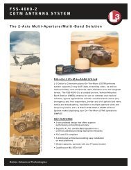
ELECTRODYNAMICS, INC Doc. No. <strong>6310034</strong>Rolling Meadows, IL 60008Revision: E1.2.2 Packaginga. Coated surfaces shall be protected from damage during shipment and storage.b. When applicable, egg crate shipping containers are recommended during all storageand handling of the components. Each item should be individually packaged to preventcontact of adjacent items (e.g., in their own egg crate cell).1.2.3 IllustrationsThe following illustrations depict “Acceptable” and “Unacceptable” workmanship results.Acceptable <strong>Workmanship</strong>Unacceptable <strong>Workmanship</strong>AAnodizing UniformAnodizing Not UniformBNo Foreign Material On ThreadsForeign Material On ThreadsCNo Anodizing Missing On ThreadsAnodizing Missing On ThreadsUse or disclosure of data on this sheet is subject to the restriction on the title page of this document.Page 14 of 61
ELECTRODYNAMICS, INC Doc. No. <strong>6310034</strong>Rolling Meadows, IL 60008Revision: EAcceptable <strong>Workmanship</strong>Unacceptable <strong>Workmanship</strong>DScratched/Nicked AnodizingEAnodizing NotScratched/Nicked/Peeling/Flaking orPittedPeeling/FlakingPittedFNo/Slight Dark SpotsDark SpotsNote: Part Shown Is Clear Anodized per MIL-A-8625, Type I, Class 1 (Ref. PN 098A60 & 098A61).Use or disclosure of data on this sheet is subject to the restriction on the title page of this document.Page 15 of 61
ELECTRODYNAMICS, INC Doc. No. <strong>6310034</strong>Rolling Meadows, IL 60008Revision: E1.3 BLACK OXIDEReference: MIL-DTL-13924D Notice 1 – Coating, Oxide, Black, for Ferrous Metals, Paragraph(s):3.7, 4.4.1.1.3.1 Acceptable <strong>Workmanship</strong>a. MIL-DTL-13924: 3.7 Coverage and color. Class 1, 2, 3, and 4 coatings (see 1.2 perMIL-DTL-13924) shall cover the basis metal completely and shall pass the smut test.The color shall be a uniform black. A slight amount of smut, which is inherent in theprocess, shall not be cause for rejection. There shall be no indication of any reddishbrownor green smut when tested as in 4.4.1. Smut "spottiness" shall be classified asunsatisfactory and shall require reprocessing.b. MIL-DTL-13924: 4.4.1 Smut test. The test shall be made prior to application ofcorrosion preventive compound or after vapor degreasing. Each black oxide coatedpiece shall be inspected visually under strong light to assure a satisfactory appearance.Each sample shall also be wiped with a clean white cloth for indications of smut (see3.7 MIL-DTL-13924). A slight amount of smut which is inherent in the process isacceptable for all classes of coatings and shall not be cause for rejection.1.3.2 Packaginga. Coated surfaces shall be protected from damage during shipment and storage.b. When applicable, egg crate shipping containers are recommended during all storageand handling of the components. Each item should be individually packaged to preventcontact of adjacent items (e.g., in their own egg crate cell).1.3.3 IllustrationsThe following illustrations depict “Acceptable” and “Unacceptable” workmanship results.Acceptable <strong>Workmanship</strong>Unacceptable <strong>Workmanship</strong>ABlack Oxide Is UniformUse or disclosure of data on this sheet is subject to the restriction on the title page of this document.Page 16 of 61
ELECTRODYNAMICS, INC Doc. No. <strong>6310034</strong>Rolling Meadows, IL 60008Revision: E1.4 CHROMATE (A.K.A. IRRIDITE, ALODINE OR CHEMICAL CONVERSION COATING)Reference: MIL-DTL-5541F - Chemical Conversion Coatings on Aluminum and Aluminum Alloys,Paragraph(s): 3.5 and 6.8.1.4.1 Engineering Drawing Call Out: In the event the engineering drawing does not call out aspecific chromate color, the color shall be yellow. Clear chromate shall only be used whenexplicitly specified on the engineering drawing primarily due to the inherent difficulties ofvisually discerning the presence of clear chromate.1.4.2 Acceptable <strong>Workmanship</strong>a. MIL-DTL-5541: 3.5 Appearance. The chemical conversion coating shall be continuousin appearance and visibly discernible in daylight. It shall be free from areas of powderyor loose coating, voids, scratches, flaws, and other defects or damages which reducethe serviceability of items or are detrimental to the protective value and paint bondingcharacteristics. The size and number of contact marks shall be minimal, consistent withgood practice. If specified in the contract or order, contact marks shall be touched upwith MIL-DTL-81706 material approved on QPL- 81706 for the applicable type; class,form, and method to prevent localized corrosion (see 6.4 and 6.8 MIL-DTL-5541).b. MIL-DTL-5541: 6.8 Visual appearances. The simplest way to evaluate a conversioncoating is to observe color, continuity in appearance; smoothness and adhesion to thebase metal (see 3.5 MIL-DTL-5541). Visual examination is performed to ensure thatproper cleaning and coating procedures were used such that a coating with sufficientprotection exists over the entire item. Materials qualified under MIL-DTL-81706produce coatings that range in color from clear/colorless to iridescent yellow, brown,gray, or blue. It may be possible to develop acceptable color levels for a particularcoating system by use of color chips. The following circumstances may exist that relateto color uniformity:a. When several alloys are processed with the same conversion chemical, color mayvary from alloy to alloy.b. Due to the high level of impurities and oxidation on the surfaces of aluminum weldsand castings, color may not be as uniform as that obtained by treating wroughtalloys.c. Dark spots may result from dripping or rundown of the conversion chemicals whenthe items are lifted out of the treatment tank. A small amount of spotting does notresult in coating degradation but must be minimized by quickly rinsing the itemsafter treatment, and use of proper racking techniques (reference 6310058).1.4.3 Packaginga. Coated surfaces shall be protected from damage during shipment and storage.Use or disclosure of data on this sheet is subject to the restriction on the title page of this document.Page 17 of 61
ELECTRODYNAMICS, INC Doc. No. <strong>6310034</strong>Rolling Meadows, IL 60008Revision: Eb. When applicable, egg crate shipping containers are recommended during all storageand handling of the components. Each item should be individually packaged to preventcontact of adjacent items (e.g., in their own egg crate cell).1.4.4 IllustrationsThe following illustrations depict “Acceptable” and “Unacceptable” workmanship results.Acceptable <strong>Workmanship</strong>Unacceptable <strong>Workmanship</strong>AChromate Is UniformChromate Is Not UniformBMinor Dark SpotsExcessive Amount of Scratches (No MoreThan 5 Isolated Spots)Use or disclosure of data on this sheet is subject to the restriction on the title page of this document.Page 18 of 61
ELECTRODYNAMICS, INC Doc. No. <strong>6310034</strong>Rolling Meadows, IL 60008Revision: E1.5 DUAL FINISH1.5.1 Definitionsa. Dual Finish – An item that has two different types of finishes, coatings, or platings.1.5.2 Acceptable <strong>Workmanship</strong>a. There shall be no contamination on the finish.b. The separating line for the finishes shall be as specified on the engineering drawing.c. Each finish shall be as specified in this manual.1.5.3 Packaginga. Coated surfaces shall be protected from damage during shipment and storage.b. When applicable, egg crate shipping containers are recommended during all storageand handling of the components. . Each item should be individually packaged toprevent contact of adjacent items (e.g., in their own egg crate cell).1.5.4 IllustrationsThe following illustrations depict “Acceptable” and “Unacceptable” workmanship results. Shownbelow are items that are dual finished with black anodized and clear chromate.Acceptable <strong>Workmanship</strong>Unacceptable <strong>Workmanship</strong>ANo Foreign Material/DiscolorationForeign Material/Severe DiscolorationBAnodizing Completely RemovedAnodizing Not Completely RemovedUse or disclosure of data on this sheet is subject to the restriction on the title page of this document.Page 19 of 61
ELECTRODYNAMICS, INC Doc. No. <strong>6310034</strong>Rolling Meadows, IL 60008Revision: EAcceptable <strong>Workmanship</strong>Unacceptable <strong>Workmanship</strong>CMinor Discoloration Immediately AroundCenter Hole1.6 ELECTROLESS NICKELReference: MIL-DTL-26074F Notice 1 – Coatings, Electroless Nickel, Paragraph(s): 3.6.2. (Note:Per Notice 1, MIL-DTL-26074F has been superseded by either MIL-DTL-32119 and SAE AMS-C-26074 depending upon the application. For L-3 EDI’s applications, SAE AMS-C-26074 shall be thesuperseding specification.)1.6.1 Acceptable <strong>Workmanship</strong>a. The nickel coating shall be smooth, adherent, and free from visible blisters, pits, nodules,porosity, cracks and other defects.1.6.2 Packaginga. Coated surfaces shall be protected from damage during shipment and storage.b. When applicable, egg crate shipping containers are recommended during all storage andhandling of the components. . Each item should be individually packaged to preventcontact of adjacent items (e.g., in their own egg crate cell).1.6.3 IllustrationsThe following illustrations depict “Acceptable” and “Unacceptable” workmanship results.Acceptable <strong>Workmanship</strong>Unacceptable <strong>Workmanship</strong>ANickel is UniformUse or disclosure of data on this sheet is subject to the restriction on the title page of this document.Page 20 of 61
ELECTRODYNAMICS, INC Doc. No. <strong>6310034</strong>Rolling Meadows, IL 60008Revision: EAcceptable <strong>Workmanship</strong>Unacceptable <strong>Workmanship</strong>ESlight Surface Abrasion Marks(ML1510 Case PN 400185 Example Shown)AMATURE PN 038C120FNo Peeling, Pitting, Discoloration orVisible Oxidation (i.e., Corrosion)Moderate Plating Discoloration/Oxidation(Likely Substrate Bleed-Thru/Plating TooThin)Use or disclosure of data on this sheet is subject to the restriction on the title page of this document.Page 21 of 61
ELECTRODYNAMICS, INC Doc. No. <strong>6310034</strong>Rolling Meadows, IL 60008Revision: EAcceptable <strong>Workmanship</strong>Unacceptable <strong>Workmanship</strong>GSlight Discoloration / Oxidation (i.e.,Corrosion)Severe Discoloration / Oxidation(Likely Substrate Bleed-Thru/Plating TooThin)Use or disclosure of data on this sheet is subject to the restriction on the title page of this document.Page 22 of 61
ELECTRODYNAMICS, INC Doc. No. <strong>6310034</strong>Rolling Meadows, IL 60008Revision: E1.7 ELECTRODEPOSITED TINReference: ASTM B 545 – Standard Specification for Electrodeposited Coatings of Tin,Paragraph(s): 6.3 - 6.5.1.7.1 Engineering Drawing Call Out: In the event the engineering drawing does not call out aspecific tin composition, the tin composition shall contain a minimum of 3% lead.1.7.2 Acceptable <strong>Workmanship</strong>a. ASTM B 545: 6.3 Appearance — Tin coatings shall have the characteristic appearance,including surface texture (4.3 per ASTM B 545), for the process used. The appearanceshall be uniform throughout, insofar as the basis metal will permit. They shall beadherent and visually free of blisters, pits, peeled areas, cracks, nodules, and unplatedareas. They shall not be stained or discolored. Flow-brightened coatings shall be freeof dewetted areas and beads. All surfaces shall be substantially free of grease or oilused in the flow-brightening process.b. ASTM B 545: 6.4 All tin-coated articles shall be clean and undamaged. Whennecessary, preliminary samples showing the finish shall be supplied to and approved bythe purchaser. Where a contact mark is inevitable, its location shall be subject toagreement between the supplier and the purchaser.c. ASTM B 545: 6.5 Thickness of Coatings—Tin coatings on articles shall conform to thethickness requirements specified in 4.2 of ASTM B 545 as to the minimum thickness onsignificant surfaces.d. Coatings shall be free of visible mechanical damage and similar gross defects whenviewed at up to 4X magnification.1.7.3 Packaginga. Coated surfaces shall be protected from damage during shipment and storage.b. When applicable, egg crate shipping containers are recommended during all storageand handling of the components. Each item should be individually packaged toprevent contact of adjacent items (e.g., in their own egg crate cell).Use or disclosure of data on this sheet is subject to the restriction on the title page of this document.Page 23 of 61
ELECTRODYNAMICS, INC Doc. No. <strong>6310034</strong>Rolling Meadows, IL 60008Revision: E1.7.4 IllustrationsThe following illustrations depict “Acceptable” and “Unacceptable” workmanship results.Acceptable <strong>Workmanship</strong>Unacceptable <strong>Workmanship</strong>ATin Is UniformBSlight Surface MarringUse or disclosure of data on this sheet is subject to the restriction on the title page of this document.Page 24 of 61
ELECTRODYNAMICS, INC Doc. No. <strong>6310034</strong>Rolling Meadows, IL 60008Revision: E1.9.1 Acceptable <strong>Workmanship</strong>a. MIL-PRF-22750F: 3.7.2 Surface appearance. The coating shall dry to a smooth,uniform surface, free from runs, sags, bubbling; streaks, hazing, seeding, dusting,floating, mottling, or other film defect when applied to test panels in accordance with 4.5through 4.5.2 of MIL-PRF-22750.1.9.2 Packaginga. Coated surfaces shall be protected from damage during shipment and storage.b. When applicable, egg crate shipping containers are recommended during all storageand handling of the components. Each item should be individually packaged to preventcontact of adjacent items (e.g., in their own egg crate cell).1.9.3 IllustrationsThe following illustrations depict “Acceptable” and “Unacceptable” workmanship results.Acceptable <strong>Workmanship</strong>Unacceptable <strong>Workmanship</strong>APaint Is UniformUse or disclosure of data on this sheet is subject to the restriction on the title page of this document.Page 26 of 61
ELECTRODYNAMICS, INC Doc. No. <strong>6310034</strong>Rolling Meadows, IL 60008Revision: ESECTION 2 – ELECTRICAL AND ELECTRONIC ITEMS (PARTS AND ASSEMBLIES)2. Electrical And Electronic Parts and AssembliesSection 2 covers electrical and electronic parts and assemblies (e.g., Active and PassiveElectronic Components, Cut-To-Length or Stripped Wire or Cable, Cable Assemblies, WiringHarnesses, Interconnects, Printed Circuit/Wiring Boards (PCBs/PWBs), Tabbing Boards,Interconnect Assemblies, Printed Card/Printed Wiring Assemblies (PCAs/PWAs) andTabbing Board Assemblies including their parent end-items, such as: Data Recorders,Electronic Safe Arm Devices, Hour Meters, Event Counters, Fault Indicators, Readers, LedIndicators, etc.). PCA’s/PWA’s are often also called Circuit Card Assemblies (CCA’s).2.1 Active/Passive Electronic Component (A/PEC) Authenticity / Counterfeit PreventionAnd Detection2.1.1 Scope: This subsection applies to A/PECs that are later sold to our customers either as-isor incorporated into an end-item/finished good, regardless of whether such parts areprocured as discrete items, or integrated into electronic assemblies or equipment by L-3 EDIor our supply-base.While the primary focus of this subsection and WI-02-01-02 (Counterfeit Part Risk MitigationPlan) is to mitigate the risk of counterfeit A/PECs from entering our customers’ supply chain,this shall not preclude the usage and tailoring of these documents to manage the risk ofcounterfeit parts of other commodities.2.1.2 Definitions: See WI-02-01-02, Counterfeit Part Risk Mitigation Plan, for definitions.2.1.3 Reference and Related Documents:a. L-3 EDI Form 1002, Supplier Quality Assurance Requirements, Clause 1.*b. L-3 EDI WI-02-01-02, Counterfeit Parts Risk Mitigation Plan.*c. IDEA-STD-1010, Acceptability of Electronic Components Distributed in the OpenMarket.d. SAE AS5553, Counterfeit Electronic Parts; Avoidance, Detection, Mitigation, andDisposition (DoD Adopted).* Note: External to L-3 EDI, these documents are available on L-3 EDI’s website at http://www.l-3com.com/edi/supplier_info.htm or http://www.l-3com.com/edi/customer_info.htm.2.1.4 GeneralSee VI, Counterfeit Parts for further information.Based on a determination of consumers risk, a representative sample(up to and including 100% inspection) should be visually examined fromeach lot (date code) of APECs procured from an IndependentDistributor, as a mininmum, at a recommended magnification of up to40X dependent upon the part’s size and characteristic being verified.Use or disclosure of data on this sheet is subject to the restriction on the title page of this document.Page 27 of 61
ELECTRODYNAMICS, INC Doc. No. <strong>6310034</strong>Rolling Meadows, IL 60008Revision: EL-3 EDI requires all Turn Key Contract Manufacturers buying APECS for Card/PrintedWiring Assemblies (CCAs/PWAs), Tabbing Board Assemblies, and other types of ElectronicAssemblies to have an established Counterfeit Parts Risk Mitigation Plan documenting therisk mitigation strategy and methodologies to be employed that is acceptable to L-3 EDI.Turn Key Contract Manufacturers are encouraged to model their control plan based uponSAE AS5553 available from the Society of Automotive Engineers (SAE) at www.sae.org.IDEA-STD-1010, Acceptability of Electronic Components Distributed in the Open Market,may be used as a best-practice guideline for conducting visual inspection and verification ofAPECs authenticity.2.1.5 CriteriaExamples of visual accept/reject critieria and tell-tale counterfeit indications include, butshall not be limited to:a. Poor quality part marking. Marking is faded. Type style, font size or color change isevident or data on a single line is located at different heights.b. Item shows evidence of wear or prior use.c. Chips on the package which may indicate excessive or careless handling.d. Scratches on the surface of the package.e. Inconsistent lead/termination plating coverage.f. Leads/terminations bent.g. Leads/terminations show evidence of previous attachment (solder present, metalupset or marred).h. Leads/terminations show arcing, discoloration, pitting, or corrosion.i. Leads/terminations are loose, missing or show metal/plating upset.j. Lead/Termination finish designator in the part number not consistent with theterminal finish on the part.k. Inconsistent texture/color or unleveled coating on the top and/or bottom sides of thepart.l. Rough surface texture in the normally smooth Pin 1 indicators area.m. Cracks in the package that may signify thermal stress.n. Cracks in the seals around leads/terminations.o. Mold pin marking areas not smooth, clean, or from part-to-part not consistent.p. Presence of numerous date codes on one individual/unit container. i.e., reel, tube,tray, etc. or within the lot in general.q. Item is unusually boxed or packed.r. Markings inconsistent with standard OEM marking content and format.s. Originality and applicability of Certificates of Conformance or other certifications/datashould be examined against the supplied item, including, but not limited to:i. Lot and/or date codes on the packaging match the lot and/or date codes onthe parts.ii. Manufacturer’s logo or label is absent, or does not match that which is shownon their website, on previous shipments, or on the parts.Use or disclosure of data on this sheet is subject to the restriction on the title page of this document.Page 28 of 61
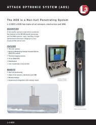
ELECTRODYNAMICS, INC Doc. No. <strong>6310034</strong>Rolling Meadows, IL 60008Revision: Eiii. Poor use of English, misspelled words, alterations, or changes to thedocumentation.iv. The use of correction fluid or correction tape is evident.v. Type style, size or pitch change is evident.vi. The document is not signed, initialed when required, is excessively faded orunclear (indicating multiple, sequential copying) or data is missing.vii. The name of the document approver or his title cannot be determined, ortyped approval name and approval signature do not match.viii. Certification or test results are identical between items when normalvariations should be expected.ix. Document traceability is not clear. The documentation should be traceable tothe items procured.x. Documentation is not delivered as required on the purchase order or is in anunusual format.xi. Data on a single line is located at different heights.xii. Documents copied.xiii. Corrections are not properly lined-out, initialed and dated.xiv. Text on page ends abruptly and number of pages conflicts with transmittal.xv. Lines on forms are bent, broken, or interrupted indicating data has beendeleted or exchanged (cut and paste).NOTEA free website named ic photos providing photographs of A/PECs can be used forauthentication comparison purposes.For L-3 EDI personnel, report any suspect-counterfeit/counterfeit part to management.For L-3 EDI supply-base, report any suspect-counterfeit/counterfeit part to L-3 EDI’s Buyer.2.1.6 IllustrationsThe following illustrations depict “Unacceptable” results.Photos Courtesy of L-3 Cincinnati ElectronicsUnacceptable <strong>Workmanship</strong>ARemarkingUse or disclosure of data on this sheet is subject to the restriction onthe title page of this document.Page 29 of 61
ELECTRODYNAMICS, INC Doc. No. <strong>6310034</strong>Rolling Meadows, IL 60008Revision: EUnacceptable <strong>Workmanship</strong>BPart Suspect of Previously Being Used; Residual Solder & Bent LeadsCMissing/Bent LeadsDCorrosion/Oxidation on LeadsEExposed Copper on LeadsUse or disclosure of data on this sheet is subject to the restriction on the title page of this document.Page 30 of 61
ELECTRODYNAMICS, INC Doc. No. <strong>6310034</strong>Rolling Meadows, IL 60008Revision: EUnacceptable <strong>Workmanship</strong>FSuspect Counterfeit on RightGDifferent Manufacturer Marking On Top and Bottom of Same ComponentHTop Appears RecoatedAfter Chemical Cleaning(Pay Close Attention to Consistency of Marking Font, Color & Alignment)Use or disclosure of data on this sheet is subject to the restriction on the title page of this document.Page 31 of 61
ELECTRODYNAMICS, INC Doc. No. <strong>6310034</strong>Rolling Meadows, IL 60008Revision: EUnacceptable <strong>Workmanship</strong>IInconsistent Mold PinsDirty Mold Pin AreasJSuspect Black Topping; Noticeable Color/Gloss Difference Between Top & SideUse or disclosure of data on this sheet is subject to the restriction on the title page of this document.Page 32 of 61
ELECTRODYNAMICS, INC Doc. No. <strong>6310034</strong>Rolling Meadows, IL 60008Revision: EUnacceptable <strong>Workmanship</strong>KConsiderable Difference in Lead Thickness & Shape; Suggests Original Plating MayHave Been Removed and Re-PlatedDeformed Part EdgeLikely Because ofSandingLRoughness/SandingMarksManufacturer’s IndentMold Area AlmostSanded CompletelyAwayComponent Body Surface Roughness/Sanding EvidentUse or disclosure of data on this sheet is subject to the restriction on the title page of this document.Page 33 of 61
ELECTRODYNAMICS, INC Doc. No. <strong>6310034</strong>Rolling Meadows, IL 60008Revision: E2.2 Cut-To-Length or Stripped Wire or Cable, Cable Assemblies, Wiring Harnesses, andOther Interconnect Devices/Assemblies2.2.1 Scope: This subsection applies to Cut-To-Length or Stripped Wire or Cable, CableAssemblies, Wiring Harnesses, and Other Interconnect Devices/Assemblies, excludingthose in 2.3 and 2.4 below.2.2.2 Defect Definitions: Unless otherwise specified, defect definitions shall be as specified inANSI/ IPC J-STD-001 (Requirements for Soldered Electrical and Electronic Assemblies(DoD Adopted)) and/or IPC / WHMA-A-620 (Requirements and Acceptance for Cable andWire Harness Assemblies).2.2.3 Reference and Related Documents:a. ANSI / IPC J-STD-001, Requirements for Soldered Electrical and ElectronicAssemblies (DoD Adopted).b. IPC / WHMA-A-620, Requirements and Acceptance for Cable and Wire HarnessAssemblies.2.2.4 ApplicabilityThe following applicability shall govern:a. If an L-3 EDI engineering drawing, specification or other governing documentspecifies ANSI / IPC J-STD-001 and does NOT specify IPC / WHMA-A-620, bothANSI / IPC J-STD-001 and ANSI / IPC-A-620shall apply via virtue of thisworkmanship manual.b. If an L-3 EDI engineering drawing, specification or other governing document doesNOT specify either ANSI / IPC J-STD-001 or IPC / WHMA-A-620, both ANSI / IPC J-STD-001 and IPC / WHMA-A-620 shall apply via virtue of this workmanship manual.c. The Testing Requirements in Section 19 (Testing) of IPC/WHMA-A-620 shall applyas follows:i. L-3 EDI “Make” Items: Since L-3 EDI does not typically provide to ourcustomers Cut-To-Length or Stripped Wire or Cable, Cable Assemblies,Wiring Harnesses, and other Interconnect Devices/Assemblies as adedicated end-item, Section 19 shall be used a as a guideline to develop ouroverall test program for a specific end-item.ii.L-3 EDI “Buy” Items: Unless otherwise specified in writing by L-3 EDI’sBuyer, L-3 EDI’s suppliers shall comply with the test requirements specifiedtherein ONLY for Cable Assemblies, Wiring Harnesses, and applicablesimilar Interconnect Devices/Assemblies.Use or disclosure of data on this sheet is subject to the restriction on the title page of this document.Page 34 of 61
ELECTRODYNAMICS, INC Doc. No. <strong>6310034</strong>Rolling Meadows, IL 60008Revision: E2.2.5 Order of Precedence:In the event of conflict, the following order of precedence shall applya. Contract or purchase order.b. L-3 EDI engineering drawing or specification.c. ANSI / IPC J-STD-001.d. IPC / WHMA-A-620.2.2.6 <strong>Workmanship</strong> Requirements:Unless otherwise specified, the following workmanship requirements shall apply, as aminimum.<strong>Workmanship</strong> StandardANSI / IPC J-STD-001Systems Product Group(SPG) Items(e.g., Data Recorders,ESAFs) †Class 3(High PerformanceElectronic Products)Components Product Group(CPG) Items(e.g., Hour Meters, EventCounters, Fault Indicators,Readers, LED Indicators) †Class 1(General Electronic Products)IPC / WHMA-A-620 ¥ Class 3 ¥(High PerformanceElectronic Products)Class 1 ¥(General Electronic Products)† L-3 EDI Purchase Orders (POs) for Systems Products Groups’ (SPG) purchases can bereadily distinguished from Components Products Groups’ (CPG) POs by the presence ofProject Numbers and often Contract Numbers in the body or line item of the SPG PO.¥ See 2.2.4.c.2.3 Printed Circuit Boards2.3.1 Scope: This subsection applies to Printed Circuit/Wiring Boards (PCBs/PWBs), andTabbing Boards, including those classified as rigid, flex, or rigid-flex, and tabbing boards.2.3.2 Defect Definitions: Unless otherwise specified, defect definitions shall be as specified inANSI / IPC-A-600 (Acceptability of Printed Boards).2.3.3 Reference and Related Documents:a) ANSI / IPC-A-600, Acceptability of Printed Boardsb) IPC-2221, Generic Standard on Printed Board Design* †c) IPC-2222, Rigid Organic Printed Board Structure Design* †d) IPC-2223, Flexible Printed Board Structure Design* †e) IPC-6011, General Performance Specification for Printed Boards* ¥Use or disclosure of data on this sheet is subject to the restriction on the title page of this document.Page 35 of 61
ELECTRODYNAMICS, INC Doc. No. <strong>6310034</strong>Rolling Meadows, IL 60008Revision: Ef) IPC-6012, Qualification and Performance Specification for Rigid Printed Boards* ¥g) IPC-6013, Qualification and Performance Specification for Flexible Printed Boards* ¥* Typical L-3 EDI engineering “baseline” design guidelines. Not intended to be all inclusive.† Included as part of what is commonly known as the IPC-2220 series of design specifications.¥Included as part of what is commonly known as the IPC-6010 series of qualification andperformance specifications.2.3.4 ApplicabilityThe following applicability shall govern:a. If an L-3 EDI engineering drawing, specification or other governing documentspecifies an IPC printed board specification (e.g., an IPC-6010 series specification)and does NOT specify IPC-A-600, both the cited IPC specification and ANSI / IPC-A-600 shall apply via virtue of this workmanship manual.b. If an L-3 EDI engineering drawing, specification or other governing document doesNOT specify an IPC printed board specification (e.g., an IPC-6010 seriesspecification), ANSI / IPC-A-600 should be used as a guidance specification.2.3.5 Order of Precedence:In the event of conflict, the following order of precedence shall apply:a. Contract or purchase order.b. L-3 EDI engineering drawing or specification.c. ANSI / IPC-A-600.2.3.6 <strong>Workmanship</strong> Requirements:Unless otherwise specified, the following workmanship requirements shall apply, as aminimum.<strong>Workmanship</strong> StandardANSI / IPC -A-600Systems Product Group(SPG) Items(e.g., Data Recorders,ESAFs) †Class 3(High PerformanceElectronic Products)Components Product Group(CPG) Items(e.g., Hour Meters, EventCounters, Fault Indicators,Readers, LED Indicators) †Class 1(General Electronic Products)† L-3 EDI Purchase Orders (POs) for Systems Products Groups’ (SPG) purchases can bereadily distinguished from Components Products Groups’ (CPG) POs by the presence ofProject Numbers and often Contract Numbers in the body or line item of the SPG PO.Use or disclosure of data on this sheet is subject to the restriction on the title page of this document.Page 36 of 61
ELECTRODYNAMICS, INC Doc. No. <strong>6310034</strong>Rolling Meadows, IL 60008Revision: E2.4 Circuit Card Assemblies2.4.1 Scope: This subsection applies to Circuit Card Assemblies (CCA’s) which may also becalled Printed Circuit /Printed Wiring Assemblies (PCAs/PWAs), and Tabbing BoardAssemblies.2.4.2 Defect Definitions: Unless otherwise specified, defect definitions shall be as specified inANSI/ IPC J-STD-001 (Requirements for Soldered Electrical and Electronic Assemblies(DoD Adopted)) and/or IPC-A-610 (Acceptability of Electronic Assemblies (DoD Adopted)),as applicable.2.4.3 Reference and Related Documents:a) ANSI / IPC J-STD-001, Requirements for Soldered Electrical and ElectronicAssemblies (DoD Adopted).b) IPC-A-610, Acceptability of Electronic Assemblies (DoD Adopted).2.4.4 Applicability:The following applicability shall govern:a. If an L-3 EDI engineering drawing or specification specifies ANSI / IPC J-STD-001and does NOT specify ANSI / IPC-A-610, both ANSI / IPC J-STD-001 and ANSI /IPC-A-610 shall apply via virtue of this workmanship manual.b. If an L-3 EDI engineering drawing or specification does NOT specify either ANSI /IPC J-STD-001 or ANSI / IPC-A-610, both ANSI / IPC J-STD-001 and ANSI / IPC-A-610 shall apply via virtue of this workmanship manual.c. If a requirements document specifies a legacy or cancelled military or industrystandard the following guidance should apply.i. For L-3 EDI, this should be confirmed with our customer in advance.ii.For L-3 EDI’s supply-base, this should be confirmed with L-3 EDI in advanceand written authorization should be provided before proceeding.Use or disclosure of data on this sheet is subject to the restriction on the title page of this document.Page 37 of 61
ELECTRODYNAMICS, INC Doc. No. <strong>6310034</strong>Rolling Meadows, IL 60008Revision: ELegacy Standard(Any Revision)ANSI / IPC J-STD-001Superseding Requirements(See 2.4.4c)ANSI / IPC-A-610WS-6536DOD-STD-2000MIL-STD-2000MIL-STD-454 †Class 3 (High PerformanceElectronic Products)Class 3 (High PerformanceElectronic Products)IPC-S-815† MIL-STD-454 has been superseded by MIL-HDBK-454. MIL-HDBK-454, Guideline 5(Soldering) specifies soldering to be in accordance with ANSI / IPC J-STD-001 without citing aspecific “Class”. The same requirements above for MIL-STD-454 shall apply to any MIL-HDBK-454 citations.2.4.5 Order of Precedence:In the event of conflict, the following order of precedence shall applya. Contract or purchase order.b. L-3 EDI engineering drawing or specification.c. ANSI / IPC J-STD-001.d. ANSI / IPC-A-610.2.4.6 <strong>Workmanship</strong> Requirements:Unless otherwise specified, the following workmanship requirements shall apply, as aminimum.<strong>Workmanship</strong> StandardANSI / IPC J-STD-001ANSI / IPC-A-610Systems Product Group(SPG) Items(e.g., Data Recorders,ESAFs) †Class 3(High PerformanceElectronic Products)Class 3(High PerformanceElectronic Products)Components Product Group(CPG) Items(e.g., Hour Meters, EventCounters, Fault Indicators,Readers, LED Indicators) †Class 1(General Electronic Products)Class 1(General Electronic Products)Use or disclosure of data on this sheet is subject to the restriction on the title page of this document.Page 38 of 61
ELECTRODYNAMICS, INC Doc. No. <strong>6310034</strong>Rolling Meadows, IL 60008Revision: E† L-3 EDI Purchase Orders (POs) for Systems Products Groups’ (SPG) purchases can be readilydistinguished from Components Products Groups’ (CPG) POs by the presence of Project Numbersand often Contract Numbers in the body or line item of the SPG PO.2.5 Rework, Repair and Modifications of Electronic Components, Printed Circuit Boards,and Circuit Card Assemblies2.5.1 Scope: This subsection applies to Electronic Components, Printed Circuit/Wiring Boards(PCBs/PWBs), and Circuit Card Assemblies (CCA’s), including Tabbing Boards and TabbingBoards Assemblies. CCA’s are often also called Printed Circuit/Wiring Assemblies(PCAs/PWAs).2.5.2 Defect Definitions: Unless otherwise specified, defect definitions shall be as specified in2.3 and 2.4 above.2.5.3 Reference and Related Documents:a. IPC-7711, Rework of Electronic Assemblies.b. IPC-7721, Repair and Modification of Printed Boards and Electronic Assemblies.c. L-3 EDI Form 1002, Supplier Quality Assurance Requirements, Clause 4,Nonconforming Material (NCM) and Material Review Authority (MRA).d. QOP-13-01, Control of Nonconforming Product.2.5.4 Applicability:The following applicability shall govern:a. Commercial Off-The-Shelf (COTS) Items: Subsection 2.5 shall not apply to COTSitems.b. Rework: Unless otherwise specified, any applicable required rework shall beaccomplished in accordance with, or at the very least modeled after, IPC-7711.c. Repair: Repairs shall NOT be allowed without prior customer written authority orapproval.i. From an L-3 EDI Perspective: “Customer” shall mean the customer withwhom L-3 EDI has a contract or purchase order. Unless otherwise specified,as a standard practice, L-3 EDI shall make every reasonable attempt to adoptor model to the maximum extent practical any applicable repair activities inaccordance with IPC-7721.ii.From an L-3 EDI Supply-Base Perspective: “Customer” shall mean L-3 EDI.d. Modifications: Modifications shall NOT be allowed without prior customer writtenauthority or approval, or L-3 EDI Configuration Management authorization (e.g., areleased engineering “modification” drawing), as applicable.Use or disclosure of data on this sheet is subject to the restriction on the title page of this document.Page 39 of 61
ELECTRODYNAMICS, INC Doc. No. <strong>6310034</strong>Rolling Meadows, IL 60008Revision: Ei. From an L-3 EDI Perspective: “Customer” shall mean the customer withwhom L-3 EDI has a contract or purchase order. Unless otherwise specified,as a standard practice, L-3 EDI shall make every reasonable attempt to adoptor model to the maximum extent practical any applicable modificationactivities in accordance with IPC-7721.ii.From an L-3 EDI Supply-Base Perspective: “Customer” shall mean L-3 EDI.2.5.5 Order of Precedence:In the event of conflict, the following order of precedence shall apply:a. Contract or purchase order.b. L-3 EDI engineering drawing or specification.c. IPC-7711 or IPC-7721.2.5.6 <strong>Workmanship</strong> Requirements:Unless otherwise specified, the following workmanship requirements shall apply, as aminimum.a. Rework: By definition, satisfactorily completed rework will meet the originalspecification and workmanship requirements specified in 2.3 and 2.4 above.b. Repair: By definition, the workmanship requirements specified in 2.3 and 2.4 abovemay not necessarily be applicable.c. Modification: By definition, the workmanship requirements specified in 2.3 and 2.4above may not necessarily be applicable.d. Process Controls: Adequate process controls shall exist for any rework,modification, or repair activities, including post-rework or post-repair inspection andtest.e. Inspection and Test: All reworks, modifications, and repairs shall be inspectedand/or tested after completion of the rework, modification, or repair to establishedand documented criteria. Unless otherwise specified, inspection or test shall be tothe original criteria to the maximum extent practical.Use or disclosure of data on this sheet is subject to the restriction on the title page of this document.Page 40 of 61
ELECTRODYNAMICS, INC Doc. No. <strong>6310034</strong>Rolling Meadows, IL 60008Revision: ESECTION 3 – PLASTIC ITEMS3 Plastic Items3.1 Scope: This section covers both molded and machined plastic items.3.2 Defect Definitions:a. Blow-Hole - A cavity or hole in the molded item typically formed due to the air or gasventing to the surface during curing process. In comparison to a pit, a blow-hole ischaracterized by either a continuous bottom or continuous (e.g., 360°) side wall NOTbeing evident.b. Blush - Discoloration or change in gloss.c. Broken - General damage. Example bent and broken tabs or ribs.d. Bubbles - Void pockets, bulge or protrusion.e. Burns - Brown marks and streaks.f. Contamination - Large areas of discoloration from foreign matter or foreign materialembedded in the surface.g. Cracking - Stress induced splitting or fissures causing separation of material.h. Crazing - Multiple tiny cracks due to stress exerted on the item.i. Delamination - Separation of layers of plastic.j. Discoloration - Any change from original color. Unintended and inconsistent color.k. Drag Marks - Cluster of scratches from plastic dragging against mold detail.l. Flash - Excess plastic at parting line or mating surface of the mold. Normally very thinand flat protrusion of plastic along an edge of a item.m. Gouge - Surface imperfection due to abrasion that removes small amount of material.n. Haze - Cloudiness on a transparent item.o. Nicks - Like gouges but of short length.p. Orange Peel - Rippled or mottled appearance view able as concentric lines.q. Pit – A crater-like imperfection on the surface of the item. In comparison to a blowhole.a pit is characterized by a continuous bottom and continuous (e.g., 360°) sidewall being evident.r. Scratch - Surface imperfection due to abrasion that removes small amounts ofmaterial.s. Short Shot - Missing plastic due to incomplete filling of the mold cavity.t. Sink - Surface depression caused by non uniform material solidification and shrinkage.u. Specks - Small discolored points of matter embedded in the surface.v. Splay - Off color streaking.3.3 Gate and Surface Conditions:a. The items gate location and size (e.g., length x width x height) shall be as specified onthe engineering drawing.b. If a gate location and size (e.g., length x width x height) is not specified on theengineering drawing, it is the responsibility of the supplier to obtain in writingacceptable gate locations and size from L-3 EDI’s buyer prior to producing the item.Use or disclosure of data on this sheet is subject to the restriction on the title page of this document.Page 41 of 61
ELECTRODYNAMICS, INC Doc. No. <strong>6310034</strong>Rolling Meadows, IL 60008Revision: Ec. Unless otherwise specified on the engineering drawing, ALL three of the following flashcriteria shall be satisfied:CriteriaEngineeringDrawings SpecifyingThat “No Flash” IsAcceptableOther EngineeringDrawings1. Flash shall be within thespecified limits of size forthe item’s feature (e.g.,item’s width)Requirement, if any, as specified on theengineering drawing.2. Flash itself shall be withinits specified limits of size(i.e., L X W X H) andlocation.
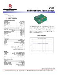
ELECTRODYNAMICS, INC Doc. No. <strong>6310034</strong>Rolling Meadows, IL 60008Revision: ESECTION 4 – VIEWING WINDOW OF EVENT COUNTERS AND HOUR METERS4 Viewing Window Of Event Counters And Hour Meters4.1 This workmanship section covers all windows used to readily enable viewing of the EventCounters and Hour Meters readouts.4.2 In general, Hour Meters workmanship criteria shall be in accordance with MIL-M-7793 (Meter,Time Totalizing), and Event Counters in accordance with MIL-I-8974 (Indicators, EventCounting).4.3 The purpose of this workmanship standard is to provide specific criteria regarding what isacceptable related to streaks, smears, or markings.a. Streaks: See photographs below for detail illustrations of acceptable streaks. Theviewing window shall be of such condition to readily enable clearly viewing thenumber wheel digits without visual distortion.b. Foreign Objects: See photos below for detail illustrations of unacceptable foreignobject debris (FOD). Viewing window shall be free from debris such as fibers, hairs,flux, solder, and/or any other type of debris that could possibly entangle in theinternal gearing mechanisms (reference Section VI, FOD).4.4 IllustrationsThe following illustrations depict “Acceptable” and “Unacceptable” workmanship results.Acceptable <strong>Workmanship</strong>Unacceptable <strong>Workmanship</strong>AClear Streaks In Viewing Window DisplayNOT Distorting Number WheelsForeign Material - Hair/Fiber In ViewingWindow DisplayUse or disclosure of data on this sheet is subject to the restriction on the title page of this document.Page 43 of 61
ELECTRODYNAMICS, INC Doc. No. <strong>6310034</strong>Rolling Meadows, IL 60008Revision: EAcceptable <strong>Workmanship</strong>Unacceptable <strong>Workmanship</strong>BPartial Clear Streak in Viewing WindowDisplay NOT Distorting Number WheelsForeign Material - Hair/Fiber In ViewingWindow DisplayCStreak In Viewing Window NOT DistortingNumber WheelsForeign Material - Flux In ViewingWindow DisplayDForeign Material - Particulate Matter InViewing Window DisplayUse or disclosure of data on this sheet is subject to the restriction on the title page of this document.Page 44 of 61
ELECTRODYNAMICS, INC Doc. No. <strong>6310034</strong>Rolling Meadows, IL 60008Revision: EAcceptable <strong>Workmanship</strong>Unacceptable <strong>Workmanship</strong>EForeign Material - Solder Curl In ViewingWindow DisplayUse or disclosure of data on this sheet is subject to the restriction on the title page of this document.Page 45 of 61
ELECTRODYNAMICS, INC Doc. No. <strong>6310034</strong>Rolling Meadows, IL 60008Revision: ESECTION 5 – 999A SERIES ETI HOUR METER AND EVENT DOUBLE UNITS5 999A SERIES ETI HOUR METER AND EVENT DOUBLE UNITS5.1 Potting Terminology:a. Blow-Hole - A cavity or hole in the potting typically formed due to the air or gasventing to the surface during curing process. A blow-hole is characterized by acontinuous bottom or 360°of side wall NOT being evident.b. Pit - A crater-like imperfection on the surface of the item. In comparison to a blowhole,a pit is characterized by a continuous bottom and 360°of side wall beingevident.c. Sink - Surface depression caused by non uniform potting solidification andshrinkage.5.2 Potting workmanship requirements shall be as specified in Section 6. All other discreteindividual workmanship requirements apply; see applicable sections.5.3 IllustrationsThe following illustrations depict “Acceptable” and “Unacceptable” workmanship results.Acceptable <strong>Workmanship</strong>Unacceptable <strong>Workmanship</strong>ACorner SeparationBSevere Separation Around FaceUse or disclosure of data on this sheet is subject to the restriction on the title page of this document.Page 46 of 61
ELECTRODYNAMICS, INC Doc. No. <strong>6310034</strong>Rolling Meadows, IL 60008Revision: EAcceptable <strong>Workmanship</strong>Unacceptable <strong>Workmanship</strong>CPits; Bottom & Sides Can Be Seen AndAre Continuous. These must be < 1% ofSurface AreaBlow Hole With No Visible BottomDBlow Hole With No Visible BottomESink; Depth > .08Use or disclosure of data on this sheet is subject to the restriction on the title page of this document.Page 47 of 61
ELECTRODYNAMICS, INC Doc. No. <strong>6310034</strong>Rolling Meadows, IL 60008Revision: EFPN 999A0064 Acceptable Potting SurfacePN 999A0064 Unacceptable PottingSurfaceUse or disclosure of data on this sheet is subject to the restriction on the title page of this document.Page 48 of 61
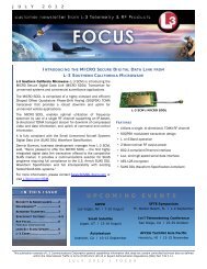
ELECTRODYNAMICS, INC Doc. No. <strong>6310034</strong>Rolling Meadows, IL 60008Revision: ESECTION 6 – E AND F FLANGE ELAPSE TIME METER CASES (Ref: PN 400A000, 410A000,430A000, 440A000, et. al.)Acceptable <strong>Workmanship</strong>Unacceptable <strong>Workmanship</strong>ASuperficial Marring/Scratches on Face(No Metal Displacement)BDents/Depressions on Face (MetalDisplaced)Slight Dents Edge of Face(Slight Metal Displacement)Dents/Depressions on Face (MetalDisplaced) & Pinhole > 1/32”Use or disclosure of data on this sheet is subject to the restriction on the title page of this document.Page 49 of 61
ELECTRODYNAMICS, INC Doc. No. <strong>6310034</strong>Rolling Meadows, IL 60008Revision: EAcceptable <strong>Workmanship</strong>Unacceptable <strong>Workmanship</strong>CPin Hole in Face > 1/32”Pin Hole in Face 1/32”(Painted to Illustrate Pin Hole)DDiscolorationUse or disclosure of data on this sheet is subject to the restriction on the title page of this document.Page 50 of 61
ELECTRODYNAMICS, INC Doc. No. <strong>6310034</strong>Rolling Meadows, IL 60008Revision: EAcceptable <strong>Workmanship</strong>Unacceptable <strong>Workmanship</strong>EColor Variance/Discoloration (Pre-Plating)Use or disclosure of data on this sheet is subject to the restriction on the title page of this document.Page 51 of 61
ELECTRODYNAMICS, INC Doc. No. <strong>6310034</strong>Rolling Meadows, IL 60008Revision: EAcceptable <strong>Workmanship</strong>O-RingGroove AreaUnacceptable <strong>Workmanship</strong>No Nicks/Dings Evident Especially InO-Ring GrooveFSmall Isolated Ding Outside of O-RingGroove - NOT Exceeding SurfaceFinish/Dimensional RequirementsFrom Small Isolated Dings Inside of O-Ring Groove (Top) Progressing ToSevere Scratches/Nicks (Bottom) –Flange- 20X magnification small dentUse or disclosure of data on this sheet is subject to the restriction on the title page of this document.Page 52 of 61
ELECTRODYNAMICS, INC Doc. No. <strong>6310034</strong>Rolling Meadows, IL 60008Revision: E7 INDICATOR FLAGSSECTION 7 - INDICATOR FLAGS7.1 Scope: <strong>Workmanship</strong> standard covers all flag indicating components installed in end-itemssuch as, but not limited to, CI70, CI75, MI51, MI57, and MI61 units.7.2 IllustrationsThe following illustrations depict “Acceptable” and “Unacceptable” workmanship results.Criteria based on visual examples shown with a maximum 10X magnification per VI,Magnification.Acceptable <strong>Workmanship</strong>Unacceptable <strong>Workmanship</strong>AMinor Single Speck - ColoredBMinor Single Speck – Not ColoredCMinor Color Variation Across ItemUse or disclosure of data on this sheet is subject to the restriction on the title page of this document.Page 53 of 61
ELECTRODYNAMICS, INC Doc. No. <strong>6310034</strong>Rolling Meadows, IL 60008Revision: EAcceptable <strong>Workmanship</strong>Unacceptable <strong>Workmanship</strong>DRough Edge (Within Limits of Size)Rough EdgeUse or disclosure of data on this sheet is subject to the restriction on the title page of this document.Page 54 of 61
ELECTRODYNAMICS, INC Doc. No. <strong>6310034</strong>Rolling Meadows, IL 60008Revision: ESECTION 8 - EVENTS & HOUR METER ETI FILL TUBE SOLDER BALL8 EVENTS & HOUR METER ETI FILL TUBE SOLDER BALL8.1 Scope: <strong>Workmanship</strong> standard covers all solder ball configuration which is acceptable forthe Elapsed Time Indicator (ETI) Event / Hour Meter Fill Tube.8.2 IllustrationsThe following illustrations depict “Acceptable” and “Unacceptable” workmanship results.Criteria based on visual examples shown with a maximum 10X magnification per VI,Magnification.Acceptable <strong>Workmanship</strong>Unacceptable <strong>Workmanship</strong>HeaderASolder Ball On Top Of Fill TubeSolder May Flow Down The Fill Tube ButShall Not Touch The Header SurfaceUse or disclosure of data on this sheet is subject to the restriction on the title page of this document.Page 55 of 61
ELECTRODYNAMICS, INC Doc. No. <strong>6310034</strong>Rolling Meadows, IL 60008Revision: E9 PACKAGING CONTAINERSSECTION 9 – PACKAGING CONTAINERS9.1 Scope: 49CFR 173.28 Reusable Plywood Shipping Crates.9.2 Acceptable <strong>Workmanship</strong> (Reference: 49CFR 173.28).Prior to container reuse, containers shall be verified to satisfy the following conditions:a. NO panel separation. Panels shall be firmly secured. See Note 1.b. NO cleat separation. Cleats shall be firmly secured. See Note 1.c. NO water damage or rot reducing the container’s structural integrity. See Note 1.d. NO wood rupture or plywood layer separation reducing the container’s structuralintegrity. See Note 1.e. NO excessive splits, breaks or cracks, or wood checking especially aroundfasteners, or other wood damage reducing the container’s structural integrity. SeeNote 1.f. NO excessive fastener holes (e.g., nail holes from previous nailing of the lid) or otherdamage that would compromise the secure fastening of the lid. See Note 1.g. NO unsecured fasteners. Fastener heads shall not be raised above the surroundingsurface (e.g., nail head popping). See Note 1.h. NO fasteners that appear NOT to be original (i.e., not consistent with the otherfasteners indicating possible rework). See Note 1.i. NO incompatible residue. The interior and exterior shall free from residue, includingmold or fungi. Staining is acceptable as long as it does NOT reduce the container’sstructural integrity. (Note: wood discoloration to a gray color is natural.) See Note 1.j. NO sharp objects protruding into the interior of the container. See Note 2.k. NO particulate material in the interior of the container. See Note 3.Notes:1. NOT reconditionable / reworkable.2. May be reconditioned / reworked ONLY if NOT part of the original container.3. May be reconditioned / reworked.Use or disclosure of data on this sheet is subject to the restriction on the title page of this document.Page 56 of 61
ELECTRODYNAMICS, INC Doc. No. <strong>6310034</strong>Rolling Meadows, IL 60008Revision: E9.3 Definition9.3.a.1.1 Checking - Cracks that occur on the ends and surfaces of wood duringdrying are known as checks. Since the ends and surfaces dry first, they tend toshrink first but are restrained by the swollen core. This result in stresses building upnear the surfaces which, if they become too great, will cause the wood to check.9.3.a.1.2 Cleats – See Figure 1.9.3.a.1.3 Panel – See Figure 1.Figure 1. Crate Anatomy.Use or disclosure of data on this sheet is subject to the restriction on the title page of this document.Page 57 of 61
ELECTRODYNAMICS, INC Doc. No. <strong>6310034</strong>Rolling Meadows, IL 60008Revision: E9.3.1 IllustrationsThe following illustrations depict “Unacceptable” workmanship.Unacceptable <strong>Workmanship</strong>ABUse or disclosure of data on this sheet is subject to the restriction on the title page of this document.Page 58 of 61
ELECTRODYNAMICS, INC Doc. No. <strong>6310034</strong>Rolling Meadows, IL 60008Revision: EUnacceptable <strong>Workmanship</strong>CDUse or disclosure of data on this sheet is subject to the restriction on the title page of this document.Page 59 of 61
ELECTRODYNAMICS, INC Doc. No. <strong>6310034</strong>Rolling Meadows, IL 60008Revision: EUnacceptable <strong>Workmanship</strong>EFUse or disclosure of data on this sheet is subject to the restriction on the title page of this document.Page 60 of 61
ELECTRODYNAMICS, INC Doc. No. <strong>6310034</strong>Rolling Meadows, IL 60008Revision: EUnacceptable <strong>Workmanship</strong>GUse or disclosure of data on this sheet is subject to the restriction on the title page of this document.Page 61 of 61