Experiment02.pdf
Experiment02.pdf
Experiment02.pdf

Create successful ePaper yourself
Turn your PDF publications into a flip-book with our unique Google optimized e-Paper software.
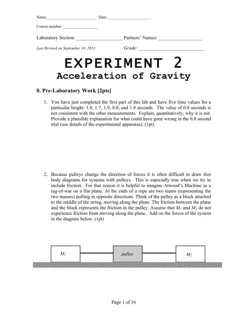
Name_________________________ Date: _____________________Course number: _________________Laboratory Section: ___________________ Partners’ Names: __________________Last Revised on September 10, 2013Grade: ___________________________EXPERIMENT 2Acceleration of Gravity0. Pre-Laboratory Work [2pts]1. You have just completed the first part of this lab and have five time values for aparticular height: 1.8, 1.7, 1.9, 0.8, and 1.9 seconds. The value of 0.8 seconds isnot consistent with the other measurements. Explain, quantitatively, why it is not.Provide a plausible explanation for what could have gone wrong in the 0.8 secondtrial (use details of the experimental apparatus). (1pt)2. Because pulleys change the direction of forces it is often difficult to draw freebody diagrams for systems with pulleys. This is especially true when we try toinclude friction. For that reason it is helpful to imagine Atwood’s Machine as atug-of-war on a flat plane. At the ends of a rope are two teams (representing thetwo masses) pulling in opposite directions. Think of the pulley as a block attachedto the middle of the string, moving along the plane. The friction between the planeand the block represents the friction in the pulley. Assume that M 1 and M 2 do notexperience friction from moving along the plane. Add on the forces of the systemin the diagram below. (1pt)M 1 pulleyM 2Page 1 of 16
Name_________________________ Date: _____________________Course number: _________________Laboratory Section: ___________________ Partners’ Names: __________________Last Revised on September 10, 2013Grade: ___________________________Experiment 2Acceleration of Gravity1. PurposeThe purpose of this experiment is to demonstrate how imperfections in theexperimental apparatus can play a large role in the final results. Friction and rotationalinertia intrinsic in the pulley have a significant effect. These extra forces mean that theacceleration of the masses is not actually the acceleration found using Equation 2.1. Youwill observe and quantify these effects. You will measure the acceleration due to frictionin the pulley bearings and the effects of the rotation of the pulley disk.In this version of the experiment, two digital photogate timers will measure theacceleration of the masses. Hand timers will also be used to understand the role that“better,” high speed equipment plays. The acceleration here at the River Campusmis9.80392 . All measurements can be compared to this value.s2. IntroductionAtwood’s machine was originally designed by George Atwood in 1784 as anexperiment demonstrating the effects of uniform acceleration. Atwood’s machine reducesthe acceleration of the masses to a fraction of the value of gravitational acceleration, andthe lower acceleration is measured to greater precision than the unchanged acceleration ofgravity with the same timing device. The smaller value of the acceleration is:M1− M2a = g . Equation 2.1M + M12Page 2 of 16
Name_________________________ Date: _____________________Course number: _________________3. Laboratory Work [18 pts]3.1 The Equation of Motion for the Atwood’s MachineTo find the equation of motion for Atwood’s machine we calculate the sum of theforces acting on the system. There are three separate forces in our system: the force ofgravity on each mass and the force due to friction in the pulley. The force due to frictionon the pulley is the sum of the tension in the strings on either side of the pulley (T 1 andT 2 ) and the weight of the pulley (M p g) multiplied by µ, the coefficient of friction.∑ F = M g − M2g− ( T + T2+ Mpg)= M11µ Equation 3.1TNote that we have defined the direction that the larger mass (M 1 ) moves the positivedirection. M T is the total mass of the system and a is the acceleration. The total mass ofAtwood’s machine is made up of three separate masses: M ,1M and2Mp. Summingeverything up we get the equation:MpM1 g − M2g− µ ( T1+ T2+ Mpg)= ( M1+ M2+ ) a. Equation 3.22M p is multiplied by a factor of ½ because the pulley is being angularly accelerated ratherthan linearly accelerated like M 1 and M 2 .a3.2 Measuring the AccelerationDigital Timer SetupDiagram of Digital SetupPlastic TubeM pM 1 >M 2Timer 1DM 1LM 2Timer 2Figure 3.1Page 3 of 16
Name_________________________ Date: _____________________Course number: _________________There are four variables that need to be measured to find the acceleration ofgravity from this setup: D, the length of the plastic tube, L, the distance between the twophotogate timers and t 1 and t 2 , the times recorded by the timers. Speed is equal to distancedivided by time. At the first timer, the speed isDv1= . Equation 3.3at1For the second timer, the speed isDv2= . Equation 3.3bt2The change between v1and v2is the acceleration. Using the kinematic equations, theacceleration can now be determined:v 2= v 1+ atEquation 3.4a2L = v11t+ 2 atEquation 3.4bFrom Equation 3.4a:v1 − v2taCombining Equation 3.4b and Equation 3.5:2v1( v2− v1) a( v2− v1)+ = L2a 2a2= D ⎛⎛ 1 1 ⎞⎞⎜⎜⎜⎜ −⎟⎟⎟⎟22L⎝⎝ t22t1⎠⎠Analog (Hand) Timer SetupDiagram of Analog Setup= Equation 3.5Equation 3.6a Equation 3.7A. BeforereleasingB. Stop timingwhen M hits floor1M pM 1 > M 2M 1M pM 2SM 2FloorM 1Page 4 of 16
Name_________________________ Date: _____________________Course number: _________________Figure 3.2In this section M starts at rest, making the kinematics equations much simpler.1Now only two variables must be measured to find the acceleration of gravity. Thedistance from the bottom of M to the floor is S. The time, t, is measured with the hand1timer.The kinematic equations for this section are similar to the previous section:v final= atEquation 3.8ay finalS =2=12 atEquation 3.8bSolving for a we find:2Sa = Equation 3.92tPage 5 of 16
Name_________________________ Date: _____________________Course number: _________________4. Measuring Acceleration Using Hand Timers andPhotogatesIn this section of the lab, photogate and hand timers are used to time the fallingmass. In both methods, the acceleration of gravity will be measured using Atwood’sMachine. The accuracy and the precision of these two methods will be compared.Equations developed in the introduction for finding the acceleration will be used in thissection, as will the statistical techniques from the previous lab. Before doing theexperiment, read the instruction of the photogate in the back.4.1 Procedure for Photogate Timers1. Measure the mass of the plastic tube, M , and its length, D.D2. Set the photogates successively along the path of the mass. (Does is matter whichof the masses passes through the photogates?)3. Measure the distance, L, from the top of one of the photogates to the top of theother photogate. Write this distance in the table below.4. Place the plastic tube around the mass that will be falling through the photogates.5. Make M1= 260 g. Remember to include the mass of the plastic tube in thismeasurement. Make M2= 240 g.6. Place the lighter mass on the floor each time, to ensure that initial conditions arethe same, and after resetting the photogate timers, let the masses drop. Do notpush the masses. (You want to measure the acceleration of gravity, and a push byanything other than gravity will skew the data.) Hold the pulley and not themasses to keep them steady for the fall.7. Record t 1and t 2in the table below. t 1should be greater than t 2. Why?8. Repeat steps 6 and 7 ten times for the mass pair to get a good estimate of theaverage value of g and the standard deviation (uncertainty) involved with timing.D = ______L = _______M = ______DM =1M + _____= 260 gDM = 240 g2Trial # t 1 (sec) t 2 (sec) Trial # t 1 (sec) t 2 (sec)1 23 45 67 89 10Page 6 of 16
Name_________________________ Date: _____________________Course number: _________________4.2 Procedure for Using Hand Timers1. When measuring the displacement of the mass hanger S, let the heavier mass M1touch the floor and use a 2 meter ruler to measure the distance from the floor to thebottom of the lighter mass holder. Place a level against the ruler to ensure that theruler is perpendicular to the floor. Do not hold the masses or the string whenmeasuring; otherwise, your measured height does not truly reflect the displacementfor the masses.2. Set M to 260 g (you may leave the plastic tube on) and M12 to 240 g, the same asthey were for the digital timers. Practice dropping the masses a couple times to get afeel for how quickly M falls. Put your hand on the pulley, not the mass, to hold them1steady before you release them.3. Use a hand timer to make ten measurements of the time it takes for the heavier massM to travel the distance S downward, and record them in the table below. It is best if1the same person who starts and stops the timer also releases the mass. The otherperson should measure the distance.M 1 = 260 gM 2 = 240 gS =______Trial # Time (sec) Trial # Time (sec)1 23 45 6Page 7 of 16
Name_________________________ Date: _____________________Course number: _________________7 89 10Page 8 of 16
Name_________________________ Date: _____________________Course number: _________________Questions [9 pts]Answer Questions 1-3 using the photogate timer data:1. Calculate the average times: t 1and t 2. Also compute the standard deviation for t 1andt2. Show at least one example for the calculation of both the average and standarddeviation. (1 pt)t1= ______t2= ______Δ t 1= ______Δ t 2= ______2. Find the average acceleration using Equation 3.7. Use the average times that you foundin Question 1. (1 pt)a = ______3. Using reasonable estimates for the error in L and D, find the uncertainty in theacceleration measured by photogate timers. Underline the term that is the largest sourceof uncertainty. (1 pt)Δa=a⎛⎛ ΔL⎜⎜⎝⎝ L2⎞⎞⎟⎟⎠⎠Δ L = ______Δ D = ______Δ a = ______⎛⎛ 2Δt+ ⎜⎜⎜⎜⎝⎝ t11⎞⎞⎟⎟⎟⎟⎠⎠2⎛⎛ 2Δt+ ⎜⎜⎜⎜⎝⎝ t22⎞⎞⎟⎟⎟⎟⎠⎠22⎛⎛ 2ΔD⎞⎞+ ⎜⎜ ⎟⎟⎝⎝ D ⎠⎠Page 9 of 16
Name_________________________ Date: _____________________Course number: _________________Answer Questions 4-6 using the hand timer data:4. Calculate the mean and standard deviation of t. (1 pt)t = ______Δ t = ______5. Find the average acceleration using Equation 3.9. Enter the average time that youfound in Question 4. (1 pt)a = ______6. Using Δ t and a reasonable estimate for the uncertainty in S, find the uncertainty forthe acceleration measured using hand timers. The equation for summing theseuncertainties is below. Show your work and underline the term that is the largest sourceof uncertainty. (1 pt)Δaa=⎛⎛ ΔS⎜⎜⎝⎝ S2⎞⎞⎟⎟⎠⎠2⎛⎛ 2Δt⎞⎞+ ⎜⎜ ⎟⎟⎝⎝ t ⎠⎠Δ S = ______Δ a = ______7. Use Equation 2.1 to calculate g measured using photogates and hand timers. AlsoM1 + M2calculate the uncertainty in each method using the equation: Δg= Δa.M1− M2mCompare your answer from each method to the accepted answer of 9.80392 given insthe introduction. (1 pt)g photogate = ______ ± ________g hand timer = ______ ± ________Page 10 of 16
Name_________________________ Date: _____________________Course number: _________________5. Correcting for the Mass of the PulleyWhen you try to move an object in a straight line it is clear that the higher themass of the object the harder you have to push in order to get the same acceleration. Asimilar rule applies to spinning objects. A car wheel is harder to spin than a bike wheelbecause the car wheel is much heavier. Spinning objects are more complicated becausetheir motion depends not only on their mass, but also how the mass is distributed aroundthe axis of rotation. You will deal with this complication formally later in the course; fornow we will confine ourselves to relatively simple objects.In the previous section you calculated the acceleration of the masses assumingthat the pulley had zero mass. However, the pulley does have mass, and is accelerated asthe masses fall. Does the acceleration of the pulley affect your measurement? Thissection will quantitatively determine the effect of the mass of the pulley on yourmeasurement of g.5.1 Procedure for Measuring Rotational Inertia1. Replace the current pulley system with the large disc pulley.2. Measure the distance between the floor and the bottom of the lighter mass as youdid in the previous sections and record the result in below.3. For each combination of M and1M listed in the table below and measure the2drop time once using the hand timers.4. Record the mass of one metal (M R ) ring below. Screw one metal ring to thepulley and repeat Step 3.5. Add another metal ring to the pulley (there should be two rings on the pulleynow) and repeat Step 3.M 1 M 2100 g 105 g100 g 110 g100 g 115 gFall Time1) M R = 0 2) M R = 3) 2M R =S = ______M R = ______Page 12 of 16
Name_________________________ Date: _____________________Course number: _________________Questions [5 pts]1. CalculateMM11− M+ M22for each combination and place your answers in the table below.Also calculate the acceleration for each trial using Equation 3.9. Show an examplecalculation below. (1 pt)MM11− M+ M22Acceleration(0 rings)Acceleration(1 ring)Acceleration(2 rings)Assuming that the mass of the pulley is negligible the acceleration of M is1Thus a plot of a vs.MM11− M+ M22M1− M2a = gEquation 5.1M + M12should result in a straight line with a slope equal to g.2. Plot a vs. the mass ratioMM11− M+ M22(y vs. x) for each set of three data points. (Draw abest-fit line.) Make sure to include a title for your plot and labels for your axes. Alsodraw a legend to label your data. It should be clear which data points correspond towhich pulley mass. (1 pt)Page 13 of 16
Name_________________________ Date: _____________________Course number: _________________3. How does your measurement of g change as the mass of the pulley increases? Hint:Try adding an appropriate best fit line to your data. Also, remember that g isproportional to the slope. (1 pt)Page 14 of 16
Name_________________________ Date: _____________________Course number: _________________4. Given the results from this section should you have included the mass of the pulley inthe first section? Consider the differences between the original pulley system and thisone and be as quantitative as possible in your answer. (2 pts)6. Summary Questions [6 pts]1. What is another significant source of error in Atwood’s machine not investigated in thelab? Explain your reasoning. (2 pt)Page 15 of 16
Name_________________________ Date: _____________________Course number: _________________2. What improvements could you make on Atwood’s machine in order to make theresults more accurate? What improvements would make the results more precise?Carefully explain your answer and use diagrams if necessary. (1 pt)3. The presence of a pulley that has mass and friction introduces significant error into themeasurements made using Atwood’s Machine. Given that Atwood’s machine contains somuch systematic error why was it used instead of directly measuring the acceleration ofan object in freefall? (1 pt)Page 16 of 16