HW-D-0103 - STI - Specified Technologies Inc
HW-D-0103 - STI - Specified Technologies Inc
HW-D-0103 - STI - Specified Technologies Inc

Create successful ePaper yourself
Turn your PDF publications into a flip-book with our unique Google optimized e-Paper software.
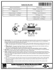
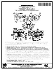
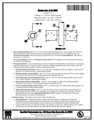
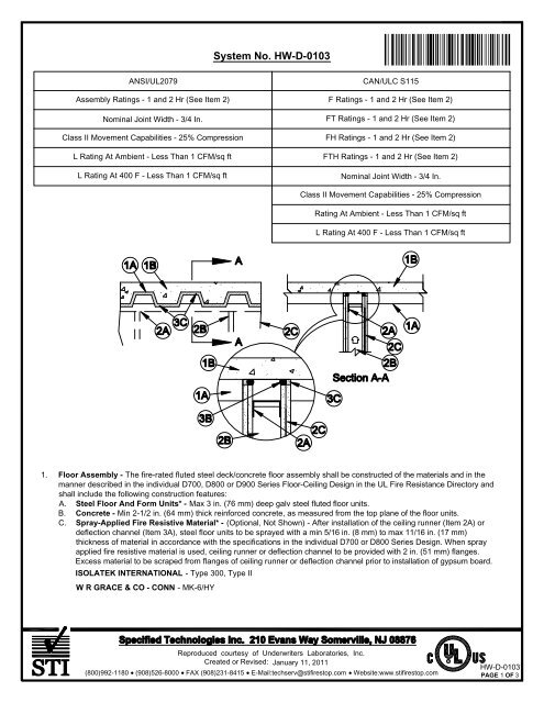
System No. <strong>HW</strong>-D-<strong>0103</strong>Ì86<strong>HW</strong>DÇ!#ÈANÇ!+-gÎANSI/UL2079Assembly Ratings - 1 and 2 Hr (See Item 2)Nominal Joint Width - 3/4 In.Class II Movement Capabilities - 25% CompressionL Rating At Ambient - Less Than 1 CFM/sq ftL Rating At 400 F - Less Than 1 CFM/sq ftCAN/ULC S115F Ratings - 1 and 2 Hr (See Item 2)FT Ratings - 1 and 2 Hr (See Item 2)FH Ratings - 1 and 2 Hr (See Item 2)FTH Ratings - 1 and 2 Hr (See Item 2)Nominal Joint Width - 3/4 In.Class II Movement Capabilities - 25% CompressionRating At Ambient - Less Than 1 CFM/sq ftL Rating At 400 F - Less Than 1 CFM/sq ft1. Floor Assembly - The fire-rated fluted steel deck/concrete floor assembly shall be constructed of the materials and in themanner described in the individual D700, D800 or D900 Series Floor-Ceiling Design in the UL Fire Resistance Directory andshall include the following construction features:A. Steel Floor And Form Units* - Max 3 in. (76 mm) deep galv steel fluted floor units.B. Concrete - Min 2-1/2 in. (64 mm) thick reinforced concrete, as measured from the top plane of the floor units.C. Spray-Applied Fire Resistive Material* - (Optional, Not Shown) - After installation of the ceiling runner (Item 2A) ordeflection channel (Item 3A), steel floor units to be sprayed with a min 5/16 in. (8 mm) to max 11/16 in. (17 mm)thickness of material in accordance with the specifications in the individual D700 or D800 Series Design. When sprayapplied fire resistive material is used, ceiling runner or deflection channel to be provided with 2 in. (51 mm) flanges.Excess material to be scraped from flanges of ceiling runner or deflection channel prior to installation of gypsum board.ISOLATEK INTERNATIONAL - Type 300, Type IIW R GRACE & CO - CONN - MK-6/HYReproduced courtesy of Underwriters Laboratories, <strong>Inc</strong>.Created or Revised: January 11, 2011(800)992-1180 (908)526-8000 FAX (908)231-8415 E-Mail:techserv@stifirestop.com Website:www.stifirestop.comR<strong>HW</strong>-D-<strong>0103</strong>PAGE 1 OF 3
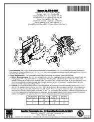
B. Studs - Steel studs to be min 3-1/2 in. (89 mm) wide. Studs cut 1/2 in. (13 mm) to 3/4 in. (19 mm) less in length thanassembly height with bottom nesting in and secured to floor runner. When deflection channel (Item 3A) is used, steelstuds attached to ceiling runner with sheet metal screws located 1/2 in. (13 mm) below the bottom of the deflectionchannel. When deflection channel is not used, studs to nest in ceiling runner without attachment.C. Gypsum Board* - Gypsum board sheets installed to a min total thickness of 5/8 in. (16 mm) and 1-1/4 in. (32 mm) oneach side of wall for 1 and 2 hr fire rated assemblies, respectively. Wall to be constructed as specified in the individualWall and Partition Design in the UL Fire Resistance Directory, except that the gypsum board is cut to follow the contourof the steel floor units with a nom 3/4 in. (19 mm) gap maintained between the gypsum board and the steel deck or thespray-applied fire resistive material. In addition, the top row of screws shall be installed into the steel studs 1/2 to 1 in.(13 to 25 mm) below the bottom edge of the ceiling runner flange.The hourly fire rating of the joint system is dependent on the hourly fire rating of the wall assembly in which it isinstalled.3. Joint System - Max separation between bottom of floor or roof deck and top of wall is 3/4 in. (19 mm). The jointsystem is designed to accommodate a max 25 percent compression from its installed width. The joint system consistsof the following:A. Deflection Channel - (Optional, Not Shown) - Max 2 in. (51 mm) deep min 24 gauge galv steel channel sized toaccommodate ceiling runner (Item 2A). Deflection channel installed perpendicular to direction of fluted steel deck prior tothe application of the sprayed-applied fire resistive material and secured to valleys with steel masonry anchors or weldsspaced max 24 in. (610 mm) OC. The ceiling runner is installed within the deflection channel to maintain a 1/2 in. (13mm) to 3/4 in. (19 mm) gap between the top of the ceiling runner and the top of the deflection channel. The ceilingrunner is not fastened to the deflection channel.B. Forming Material* - (Not Shown) - In 2 hr fire rated wall assemblies, polyethylene foam backer rod, mineral wool orglass fiber insulation friction fit into joint opening and recessed minimum 1/2 in. (13 mm) from each surface of wall. Whensound isolation clips (Item 2A4) are used to secure ceiling runner to underside of floor or roof in 1 or 2 hr fire rated wallassemblies, the space between the top of the ceiling runner and the underside of the floor or roof shall be tightly packedwith mineral wool batt insulation. The forming material shall be recessed from each surface of wall to accommodate therequired thickness of fill material. Forming material is required when sound isolation clips (Item 2A4) are used, butotherwise optional.ROCK WOOL MANUFACTURING CO - Delta SafingROCKWOOL MALAYSIA SDN BHD - SafeROXUL INC - SafeTHERMAFIBER INC - Type SAFC. Fill, Void or Cavity Material* - Sealant - Min 1/2 in. (13 mm) thickness of fill material applied within joint opening onboth sides of wall, flush with both surfaces of wall. As an option in 1 hr fire rated walls, bond breaker tape applied toceiling channel (Item 2A) or deflection channel (Item 3A) prior to installation of fill material.SPECIFIED TECHNOLOGIES INC - SpecSeal ES Sealant*Bearing the UL Classification MarkReproduced courtesy of Underwriters Laboratories, <strong>Inc</strong>.Created or Revised: January 11, 2011(800)992-1180 (908)526-8000 FAX (908)231-8415 E-Mail:techserv@stifirestop.com Website:www.stifirestop.comR<strong>HW</strong>-D-<strong>0103</strong>PAGE 3OF3