Download the thesis (PDF) - Ferguson Structural Engineering ...
Download the thesis (PDF) - Ferguson Structural Engineering ...
Download the thesis (PDF) - Ferguson Structural Engineering ...

Create successful ePaper yourself
Turn your PDF publications into a flip-book with our unique Google optimized e-Paper software.
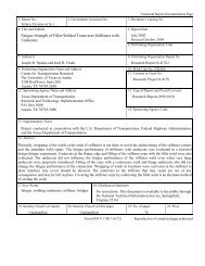
Preservation Alternatives for Historic Metal Truss Bridges:Survey of Literature and Current PracticesbyMat<strong>the</strong>w Ernest Thiel, B.S.C.E.ThesisPresented to <strong>the</strong> Faculty of <strong>the</strong> Graduate School ofThe University of Texas at Austinin Partial Fulfillmentof <strong>the</strong> Requirementsfor <strong>the</strong> Degree ofMasters of Science in <strong>Engineering</strong>The University of Texas at AustinMay 1998
Preservation Alternatives for Historic Metal Truss Bridges:Survey of Literature and Current PracticesApproved bySupervising Committee:Michael D. EngelhardtJoseph A. Yura
DedicationTo my parents, Russell and Rae Ann, who have taught, and continue to teach meso much about life.
AcknowledgementsI would like to thank <strong>the</strong> individuals who have played key roles in <strong>the</strong> completionof this <strong>the</strong>sis. Firstly, to Dr Michael D. Engelhardt, for giving me <strong>the</strong> opportunityto work on this project and guiding it, and me, through <strong>the</strong>se two years. Secondlyto <strong>the</strong> Texas Department of Transportation for funding this study. Thirdly, to <strong>the</strong>faculty and staff of <strong>Ferguson</strong> <strong>Structural</strong> <strong>Engineering</strong> Laboratory, who haveprovided me both an excellent technical background and <strong>the</strong> support necessary tocomplete my studies.On a personal note, I would also like to thank persons who have shaped my lifeover <strong>the</strong> past twenty-three years. Every person and experience in my life, hascontributed to <strong>the</strong> person I am, and will become. My parents have instilled <strong>the</strong>knowledge of right and wrong, and continue to be a model which I will ever striveto reach. My friends and time at Washington University taught me to open myeyes to <strong>the</strong> variety of people and places around me. At <strong>the</strong> University of Texas,<strong>the</strong> professors have demonstrated a level of technical expertise which will be anexample throughout my professional career. Finally toge<strong>the</strong>r with my friends inAustin we have grown through <strong>the</strong> difficulties of life with faith, perseverance,encouragement, and humor.May 1998iv
AbstractPreservation Alternatives for Historic Metal Truss Bridges:Survey of Literature and Current PracticesMat<strong>the</strong>w Ernest Thiel, M.S.E.The University of Texas at Austin, 1998Supervisor: Michael D. EngelhardtIt is a well-known fact that <strong>the</strong> condition of <strong>the</strong> nations’ bridges is poor atbest. Surveys have revealed that up to 40% of <strong>the</strong> bridges currently in service areei<strong>the</strong>r structurally or geometrically deficient.In response to <strong>the</strong> growing interest of <strong>the</strong> historical community in <strong>the</strong>preservation of Texas’ older metal truss bridges, <strong>the</strong> Texas Department ofTransportation (TxDOT) has been addressing each bridge rehabilitation on a caseby-casebasis. To streamline this process, TxDOT commissioned <strong>the</strong> Universityof Texas at Austin to conduct a series of investigations to not only increase <strong>the</strong>information available to engineers, but also test current rehabilitation techniquesas applied to metal truss bridges.To complete <strong>the</strong> first task of <strong>the</strong> project three steps were taken, which aredescribed in this paper. The first involved a literature search and cataloging ofrelevant information. The second was a survey of o<strong>the</strong>r transportation agencies todocument current trends in truss bridge rehabilitation. The third task consisted ofv
a summary of <strong>the</strong> literature search and survey of DOTs to form an in-depthcollection of common deficiencies in structures and possible solution alternatives.TABLE OF CONTENTSList of Figures ......................................................................................................... xChapter 1: Introduction ........................................................................................... 11.1 Background ............................................ Error! Bookmark not defined.1.2 Project Description ................................. Error! Bookmark not defined.1.3 Scope of Report ...................................... Error! Bookmark not defined.1.3.1 Survey of DOTs ......................... Error! Bookmark not defined.1.3.2 Literature Review ....................... Error! Bookmark not defined.1.3.3 Summary of Literature Review and DOT SurveyError! Bookmark not defined.Chapter 2: Literature Search ................................. Error! Bookmark not defined.2.1 Goals of Literature Review .................... Error! Bookmark not defined.2.2 Methodology .......................................... Error! Bookmark not defined.2.3 Summary of <strong>the</strong> Database....................... Error! Bookmark not defined.2.3.1 General Information ................... Error! Bookmark not defined.2.3.2 Rehabilitation Techniques .......... Error! Bookmark not defined.2.3.3 Evaluation ................................... Error! Bookmark not defined.2.3.4 Testing ........................................ Error! Bookmark not defined.2.3.5 References .................................. Error! Bookmark not defined.2.4 Searching Tips ........................................ Error! Bookmark not defined.2.4.1 Finding Articles .......................... Error! Bookmark not defined.2.4.2 Document Procurement .............. Error! Bookmark not defined.Chapter 3: Survey of Departments of TransportationError! Bookmark not defined.3.1 Survey Objectives .................................. Error! Bookmark not defined.3.2 Description of Survey ............................. Error! Bookmark not defined.vi
3.2.1 Survey Overview ........................ Error! Bookmark not defined.3.2.1.1 Coverletter ...................... Error! Bookmark not defined.3.2.1.2 Survey ............................. Error! Bookmark not defined.3.3 Results of <strong>the</strong> Survey .............................. Error! Bookmark not defined.3.3.1 Question 1 .................................. Error! Bookmark not defined.3.3.2 Question 2 .................................. Error! Bookmark not defined.3.3.3 Question 3 .................................. Error! Bookmark not defined.3.3.4 Question 4 .................................. Error! Bookmark not defined.3.3.5 Question 5 .................................. Error! Bookmark not defined.3.3.6 Question 6 .................................. Error! Bookmark not defined.3.3.7 Question 7 .................................. Error! Bookmark not defined.3.3.8 Question 8 .................................. Error! Bookmark not defined.3.3.9 Question 9 .................................. Error! Bookmark not defined.3.4 Follow-Up .............................................. Error! Bookmark not defined.3.5 Final Comments ..................................... Error! Bookmark not defined.Chapter 4: Summary of Literature Review and DOT SurveyError! Bookmark not defined.4.1 Introduction ............................................ Error! Bookmark not defined.4.2 Analysis and Testing of Structures......... Error! Bookmark not defined.4.2.1 Structure ..................................... Error! Bookmark not defined.4.2.1.1 <strong>Structural</strong> Analysis ......... Error! Bookmark not defined.4.2.1.2 Load Testing ................... Error! Bookmark not defined.4.2.2 Material Testing and Non-Destructive TestingError! Bookmark not defined.4.2.2.1 Material Testing ............. Error! Bookmark not defined.4.2.2.2 Non-Destructive Testing Error! Bookmark not defined.4.2.3 Discussion of Analysis and Testing of StructuresError! Bookmark not defined.4.3 Deficiencies in Structures....................... Error! Bookmark not defined.4.3.1 Functional ................................... Error! Bookmark not defined.4.3.1.1 Width .............................. Error! Bookmark not defined.vii
4.3.1.2 Height Deficiencies ........ Error! Bookmark not defined.4.3.1.3 Railing ............................ Error! Bookmark not defined.4.3.2 Damage ....................................... Error! Bookmark not defined.4.3.2.1 Corrosion Damage .......... Error! Bookmark not defined.4.3.2.2 Impact Damage............... Error! Bookmark not defined.4.3.2.3 Fire Damage ................... Error! Bookmark not defined.4.3.3 Streng<strong>the</strong>ning <strong>Structural</strong> MembersError! Bookmark not defined.4.3.3.1 Floor Beams, Girders, and StringersError! Bookmark not defined.4.3.3.2 Tension and o<strong>the</strong>r Fracture Critical MembersError! Bookmark not defined.4.3.3.3 Compression Members ... Error! Bookmark not defined.4.3.3.4 Pinned Connections ........ Error! Bookmark not defined.4.3.3.5 Riveted Connections ...... Error! Bookmark not defined.4.3.4 <strong>Structural</strong> System ....................... Error! Bookmark not defined.4.3.4.1 Deck Rehabilitation ........ Error! Bookmark not defined.4.3.4.2 Post-Tensioning .............. Error! Bookmark not defined.4.3.4.3 Additional Load Bearing SystemError! Bookmark not defined.4.3.4.4 Additional Continuity and SupportError! Bookmark not defined.Chapter 5: Summary & Recommendations ........... Error! Bookmark not defined.5.1 Summary of Findings ............................. Error! Bookmark not defined.5.2 Recommendations for Future InvestigationError! Bookmark not defined.Appendix A: Survey of Departments of TransportationError! Bookmark not defined.Appendix B: Responses to Historic Metal Truss Bridge SurveyError! Bookmark not defined.Question 1: ................................................... Error! Bookmark not defined.Question 2: ................................................... Error! Bookmark not defined.Question 3: ................................................... Error! Bookmark not defined.Question 4: ................................................... Error! Bookmark not defined.Question 5: ................................................... Error! Bookmark not defined.Question 6: ................................................... Error! Bookmark not defined.viii
Question 7: ................................................... Error! Bookmark not defined.Question 8: ................................................... Error! Bookmark not defined.Question 9: ................................................... Error! Bookmark not defined.Question 10: ................................................. Error! Bookmark not defined.Question 12: ................................................. Error! Bookmark not defined.Annotated Bibliography ........................................ Error! Bookmark not defined.Description of Annotated Bibliography ....... Error! Bookmark not defined.Introductory Information .............................. Error! Bookmark not defined.Rehabilitation Techniques ............................ Error! Bookmark not defined.General ................................................ Error! Bookmark not defined.Post-Tensioning ................................... Error! Bookmark not defined.Superimposed Truss ............................ Error! Bookmark not defined.Coverplating ........................................ Error! Bookmark not defined.Rivet Replacement .............................. Error! Bookmark not defined.Additional Members ............................ Error! Bookmark not defined.Pin Replacement ................................. Error! Bookmark not defined.Deck Replacement ............................... Error! Bookmark not defined.Flame Straightening ............................ Error! Bookmark not defined.Evaluation ..................................................... Error! Bookmark not defined.Corrosion ............................................. Error! Bookmark not defined.Fatigue & Fracture .............................. Error! Bookmark not defined.Truss Stability ..................................... Error! Bookmark not defined.<strong>Structural</strong> Analysis .............................. Error! Bookmark not defined.Non-Destructive Testing ..................... Error! Bookmark not defined.Reliability Analysis ............................. Error! Bookmark not defined.Testing .......................................................... Error! Bookmark not defined.Structure .............................................. Error! Bookmark not defined.Members .............................................. Error! Bookmark not defined.ix
Connections ......................................... Error! Bookmark not defined.Deck .................................................... Error! Bookmark not defined.Reference ...................................................... Error! Bookmark not defined.O<strong>the</strong>r References .......................................... Error! Bookmark not defined.Vita ...................................................................... Error! Bookmark not defined.x
LIST OF FIGURESFigure 3.1: Response to Question 1 ...................... Error! Bookmark not defined.Figure 3.2: Response to Question 2 ...................... Error! Bookmark not defined.Figure 3.3: Response to Question 3 ...................... Error! Bookmark not defined.Figure 3.4: Response to Question 4 ...................... Error! Bookmark not defined.Figure 3.5: Response to Question 5 ...................... Error! Bookmark not defined.Figure 3.7: Response to Question 7 ...................... Error! Bookmark not defined.Figure 3.8: Response to Question 8 ...................... Error! Bookmark not defined.Figure 3.9: Response to Question 9 ...................... Error! Bookmark not defined.Figure 4.1: Widening of Pony Truss ..................... Error! Bookmark not defined.Figure 4.2: Widening Floorbeams of a Pony TrussError! Bookmark not defined.Figure 4.3: Alteration of Portal Bracing 1 ............ Error! Bookmark not defined.Figure 4.4: Alteration of Portal Bracing 2 ............ Error! Bookmark not defined.Figure 4.6: Portal Height Warning System ........... Error! Bookmark not defined.Figure 4.7: NCHRP 222, System R-1 Retrofit RailingError! Bookmark not defined.Figure 4.8: NCHRP 222, System M-5 Retrofit RailingError! Bookmark not defined.Figure 4.9: NCHRP 222, System R-5 Retrofit Concrete RailingError! Bookmark not defined.Figure 4.10: Vermont Box Beam Railing ............. Error! Bookmark not defined.Figure 4.10: Rhode Island Box Beam Railing ...... Error! Bookmark not defined.Figure 4.12: Timber Railing System ..................... Error! Bookmark not defined.Figure 4.13: High Performance Railing System ... Error! Bookmark not defined.Figure 4.14: Low Performance Railing ................. Error! Bookmark not defined.xi
Figure 4.15: Bolted Repairs for Corroded MembersError! Bookmark not defined.Figure 4.16: Replacement of Diagonal Tension MemberError! Bookmark not defined.Figure 4.17: Impact Damage to Truss Bridge ....... Error! Bookmark not defined.Figure 4.18: Impact Damaged Member ................ Error! Bookmark not defined.Figure 4.19: Bolted Repair of Impact Damaged MemberError! Bookmark not defined.Figure 4.20: Post-tensioned Floorbeam ................ Error! Bookmark not defined.Figure 4.21: King Post Arrangements for FloorbeamsError! Bookmark not defined.Figure 4.22: Composite Action Using Pre-cast Concrete PanelsError! Bookmark not defined.Figure 4.23: New Members Added to Existing Tension MembersError! Bookmark not defined.Figure 4.24: Coverplate Options for Compressive MembersError! Bookmark not defined.Figure 4.25: Bracing Compression Chord of TrussError! Bookmark not defined.Figure 4.26: Open Grid Deck ................................ Error! Bookmark not defined.Figure 4.27: Concrete Filled Deck ........................ Error! Bookmark not defined.Figure 4.28: Plate Deck ......................................... Error! Bookmark not defined.Figure 4.29: Laminated Timber ............................ Error! Bookmark not defined.Figure 4.30: Post-Tensioning Options for Truss StructureError! Bookmark not defined.Figure 4.31: Superimposed Arch Applied to Truss StructureError! Bookmark not defined.Figure 4.32: Bailey Truss Applied to Pony Truss BridgeError! Bookmark not defined.Figure 4.33: Additional Supports Added to Truss BridgeError! Bookmark not defined.xii
xiii
CHAPTER 1INTRODUCTION1.1 BACKGROUNDIt is a well-known fact that <strong>the</strong> condition of <strong>the</strong> nations’ bridges is poor atbest. Surveys have revealed that up to 40% of <strong>the</strong> bridges currently in service areei<strong>the</strong>r structurally or geometrically deficient, [Ref. 5.9]. As an alternative todestroying inadequate bridges, a common solution involves rehabilitating <strong>the</strong>existing structure. The Texas Department of Transportation (TxDOT) isresponsible for deciding whe<strong>the</strong>r replacement or rehabilitation is <strong>the</strong> best optionfor each bridge structure. This process is complicated when <strong>the</strong> bridge inquestion is historic in nature. In response to <strong>the</strong> growing interest of <strong>the</strong> historicalcommunity in <strong>the</strong> preservation of Texas’ older metal truss bridges, TxDOT hasbeen addressing each historic bridge rehabilitation on a case-by-case basis. Theofficials at TxDOT, wishing to formulate sound engineering decisions, as well asmaintain <strong>the</strong> existing historic truss bridges of <strong>the</strong> state, commissioned TheUniversity of Texas at Austin to aid in <strong>the</strong> resolution of <strong>the</strong>se difficulties.1.2 PROJECT DESCRIPTIONThe overall objective of this project is to maintain <strong>the</strong> historic metal trussbridges of Texas in continued vehicular service. The University of Texas atAustin had been commissioned by TxDOT to produce guidelines that will aid <strong>the</strong>Texas officials in <strong>the</strong> repair and rehabilitation of historic metal truss bridges. The1
esearchers have identified tasks, which are presently being completed, to aid in<strong>the</strong> compilation of <strong>the</strong>se guidelines. There are three steps of this research project,<strong>the</strong> first of which being a review and documentation of current rehabilitationtechniques of o<strong>the</strong>r Departments of Transportation (DOTs) and an in-depthliterature review of repair techniques. The second task is <strong>the</strong> examination of twocase-study bridges. This examination will include <strong>the</strong> load testing and evaluationof possible retrofit options to streng<strong>the</strong>n <strong>the</strong> bridges. A third investigation willinvolve laboratory testing of repair and retrofit techniques as applied to bridgemembers. At <strong>the</strong> completion of this project, <strong>the</strong> researchers will produce athorough compilation of strategies that will aid <strong>the</strong> TxDOT officials in preserving<strong>the</strong> historic metal truss bridges of Texas in vehicular service.1.3 SCOPE OF REPORTThis research report represents <strong>the</strong> completion of <strong>the</strong> first task identifiedabove. To successfully carry out this step, <strong>the</strong> task was separated into threesegments. The first step was a survey of DOTs to investigate <strong>the</strong> current level ofrehabilitation undertaken by o<strong>the</strong>r agencies.The second step involvedassembling a collection of articles and documents related to truss bridgerehabilitation. Thirdly, <strong>the</strong> elements from <strong>the</strong> first two steps are condensed toprovide a summary of current rehabilitation techniques, supported with relevantliterature and <strong>the</strong> experiences of o<strong>the</strong>r transportation officials. In <strong>the</strong> followingparagraphs, a short introduction to each of <strong>the</strong>se segments will be provided.2
1.3.1 Survey of DOTsThis task involved sending mail questionnaires to o<strong>the</strong>r DOTs solicitinginformation on historic metal truss rehabilitation. The first step in completing thistask involved <strong>the</strong> development of <strong>the</strong> survey. Through discussions with TxDOTofficials and o<strong>the</strong>r researchers at <strong>the</strong> University of Texas at Austin, a collection ofnine questions was assembled. This survey was mailed to sixty transportationagencies throughout <strong>the</strong> United States and Canada. Thirty-nine responses werereceived and transcribed into a computer database. A complete summary of <strong>the</strong>survey including <strong>the</strong> methodology and techniques utilized may be found inChapter 3. A copy of <strong>the</strong> survey is located in Appendix A along with a completelisting of <strong>the</strong> responses from <strong>the</strong> DOTs in Appendix B.1.3.2 Literature ReviewThe literature review sought to collect as much relevant informationconcerning metal truss bridge rehabilitation as possible. The documentsrecovered include journal articles, books, manuals, and product information.Each document was read and summarized. The collection of material willcontinue throughout <strong>the</strong> duration of <strong>the</strong> project. For this reason, a catalogingsystem was created that would allow for, not only easy access to <strong>the</strong> includedmaterials, but also future expansion of <strong>the</strong> database. Chapter 2 provides fur<strong>the</strong>rdiscussion of <strong>the</strong> materials collected, as well as, information on literaturesearching techniques. The database of literature summaries may be found in <strong>the</strong>Annotated Bibliography.3
1.3.3 Summary of Literature Review and DOT SurveyTo collect <strong>the</strong> information ga<strong>the</strong>red in <strong>the</strong> first two parts of <strong>the</strong> project intoa useful format, a syn<strong>the</strong>sis of <strong>the</strong> information was undertaken. A collection ofcommon rehabilitation topics related to metal truss bridges was assembled.Materials from <strong>the</strong> survey of DOTs, as well as, relevant documents discovered in<strong>the</strong> literature search, were assembled for each topic and presented in Chapter 4.General topics such as <strong>the</strong> Analysis and Testing of Bridges, <strong>Structural</strong> andGeometric Deficiencies, and Damage Repair are included in this chapter.4
CHAPTER 2LITERATURE SEARCH2.1 GOALS OF LITERATURE REVIEWA major component of this study consisted of an in-depth literature search.The purpose of this search was to collect, catalog, and summarize informationrelated to metal truss bridge rehabilitation. This database of literature is intendedto serve as a resource to engineers involved with truss rehabilitation projects,providing sources of information on technical issues pertinent to older trussbridges. The database also provides information on rehabilitation techniqueswhich have been successfully implemented in o<strong>the</strong>r states, and for whichexperience and precedence of use already exist. Finally, <strong>the</strong> literature searchserved as a resource for <strong>the</strong> remainder of <strong>the</strong> study, an in particular, for <strong>the</strong> casestudy bridges.This chapter describes <strong>the</strong> methods used to conduct <strong>the</strong> literature review,provides a summary of topics covered in <strong>the</strong> review, and provides guidance onmethods to conduct more detailed searches to obtain publications. The results of<strong>the</strong> literature survey are summarized in <strong>the</strong> form of an Annotated Bibliography.A syn<strong>the</strong>sis and discussion of information found in <strong>the</strong> literature is provided inChapter 4.1
2.2 METHODOLOGYThe methodology used during this phase of <strong>the</strong> project involved severalsteps to collect <strong>the</strong> desired information. First, a list of topics and keywordsrelated to steel truss bridge rehabilitation was identified. The next step was tolocate publications related to <strong>the</strong>se topics.The preliminary literature search was conducted using <strong>the</strong> University ofTexas at Austin library database (UTCAT) which is a computerized listing ofbooks and articles available at <strong>the</strong> university. A variety publications were foundusing <strong>the</strong> UTCAT system and retrieved for <strong>the</strong> database. A second database,namely <strong>the</strong> <strong>Engineering</strong> Index (EiCPX), was also extensively referenced. Thisdatabase, available over <strong>the</strong> world-wide-web, lists articles published related toengineering topics from <strong>the</strong> 1970’s to <strong>the</strong> present. Once <strong>the</strong> articles wereobtained <strong>the</strong> articles were read, summarized, and a cited in <strong>the</strong> AnnotatedBibliography.2.3 SUMMARY OF THE DATABASEIn order to facilitate <strong>the</strong> use of <strong>the</strong> literature database, <strong>the</strong> publicationshave been categorized and cataloged into <strong>the</strong> following five major sections:1. General Information2. Rehabilitation Techniques3. Evaluation4. Testing5. Reference2
Within each major section, articles were <strong>the</strong>n fur<strong>the</strong>r categorizedaccording to topic areas. To assist in locating articles in <strong>the</strong> database, a sequentialnumbering system is used. For example, an article dealing with <strong>the</strong> evaluation offatigue and fracture in a bridge can be found at 3.2.X referring to Section 3(Evaluation), Topic 2 (Fracture and Fatigue). Some articles have been placed intomore than one group if warranted by <strong>the</strong> material and cross-referenced in <strong>the</strong>catalog. The major sections and topic areas are described in <strong>the</strong> followingparagraphs.2.3.1 General InformationThe articles in this section provide an introductory presentation of bridgepreservation, problems present in metal truss bridges, and solutions to somecommon deficiencies.2.3.2 Rehabilitation TechniquesThis section contains articles which focus on individual rehabilitationtechniques. Many different techniques are included with a wide range ofapplications. Articles covering simple rehabilitation solutions such as <strong>the</strong>addition of coverplates, to complex rehabilitation efforts involving <strong>the</strong>replacement of pins in a truss are included. These articles should aid inconsidering <strong>the</strong> full range of available options for truss rehabilitation, as well asprovide details of <strong>the</strong> various techniques. Topics in <strong>the</strong> Rehabilitation TechniquesSection include:1. General2. Post Tensioning3
3. Superimposed Truss4. Coverplating5. Rivet Replacement6. Additional Members7. Pin Replacement8. Deck Replacement9. Flame Straightening2.3.3 EvaluationThe evaluation section is comprised of references dealing with <strong>the</strong>assessment of <strong>the</strong> bridge structure. In a rehabilitation project, <strong>the</strong> key first stepsinclude structural analysis and load rating, as well as an inspection of <strong>the</strong> bridge.Articles in this section relate to appropriate methods for structural analysis oftruss bridges, as well as introductory information on non-destructive inspectionand evaluation techniques. Also included are articles on fatigue and fractureconcerns. Topics in <strong>the</strong> Evaluation Section include:1. Corrosion2. Fatigue and Fracture3. Truss Stability4. <strong>Structural</strong> Analysis5. Non-Destructive Testing6. Reliability Analysis4
2.3.4 TestingThe testing section of <strong>the</strong> catalog includes articles concerning ei<strong>the</strong>r smallor large-scale load testing of <strong>the</strong> bridge structure. To fully understand <strong>the</strong>response of a truss bridge it may be beneficial to load test ei<strong>the</strong>r <strong>the</strong> entirestructure or certain members. Articles in this section refer to some of <strong>the</strong>situations that might be presented to an engineer who would like to test a bridge,or individual members of a bridge. Topics contained in <strong>the</strong> Testing Sectioninclude:1. Structure2. Members3. Connections4. Deck2.3.5 ReferencesThe final section of <strong>the</strong> catalog, References, encompasses <strong>the</strong> moregeneral topics that may be of interest in truss bridge rehabilitation. A majority of<strong>the</strong> books found during <strong>the</strong> literature review are contained in this section. Thesedocuments provide a varied and broad discussion of <strong>the</strong> truss rehabilitation topics.2.4 SEARCHING TIPSOver <strong>the</strong> course of <strong>the</strong> literature search some obstacles in both findingpertinent references, as well as retrieving <strong>the</strong>se documents were encountered. Inretrospect, a discussion of literature searching techniques would have proveduseful. From <strong>the</strong>se experiences, this section of literature search suggestions hasbeen assembled. Hopefully <strong>the</strong>se suggestions will help future researches both at5
<strong>the</strong> University of Texas at Austin, and also engineers of <strong>the</strong> Texas Department ofTransportation.2.4.1 Finding ArticlesAs previously mentioned, <strong>the</strong> two main search engines used were <strong>the</strong>University of Texas system and <strong>the</strong> <strong>Engineering</strong> Index. Hundreds of articlereferences were available and examined to determine which would be applicableto <strong>the</strong> research. The University of Texas library resources may be accessed via<strong>the</strong> wold-wide-web at “www.utexas.edu”. By following <strong>the</strong> links to <strong>the</strong> library,<strong>the</strong> UTNetCAT system may be referenced. More in-depth article listings may besearched by linking to <strong>the</strong> “Indexes & Abstracts” <strong>the</strong>n linking to <strong>the</strong> “Science/Technology/ Health” page. The EiCPX may be accessed, as well as o<strong>the</strong>r articlesearch engines including.• Applied Science and Technology Abstracts• ArticleFirst• OCLC WorldCat• CARL UnCoverUnfortunately, <strong>the</strong> resources mentioned in <strong>the</strong> previous paragraph areavailable to university students, faculty, or at <strong>the</strong> University of Texas Library.Therefore, engineers outside <strong>the</strong> university must find alternate means of documentlocation. For engineers within close proximity of <strong>the</strong> University of Texas atAustin, access to many of <strong>the</strong>se databases may be gained by visiting <strong>the</strong> libraryand using <strong>the</strong> computer terminals inside <strong>the</strong> library. If <strong>the</strong> engineer is not locatednear a library facility with search capabilities, ano<strong>the</strong>r option is utilize various6
state databases and search engines. Engineers should check within <strong>the</strong> office foraccess to resources such as TRIS and o<strong>the</strong>r transportation information databasesavailable to state agencies. If <strong>the</strong>se services are not available, some databases areaccessible for a charge, such as EiCPX.2.4.2 Document ProcurementOnce <strong>the</strong> article or book references were collected, it was necessary toobtain a hard copy of <strong>the</strong> document. It was checked if <strong>the</strong> article was available inThe University of Texas at Austin using <strong>the</strong> electronic card catalog. If an articlewas not at <strong>the</strong> university, a document delivery service was employed. Bycompleting a request form through <strong>the</strong> on-line library system at <strong>the</strong> university, <strong>the</strong>articles were requested. If a book was not contained in <strong>the</strong> university stacks, anInterlibrary Loan (ILL) form was completed. The ILL program lends booksbetween member libraries at little or no cost to <strong>the</strong> patrons.The document delivery services might not be available to practicingengineers. To collect articles, <strong>the</strong> following steps are suggested. The first taskinvolves collecting a list of articles which are relevant to <strong>the</strong> project at hand.Information such as journal name, issue, number, and pages should be listed foreach article. The second step would involve checking <strong>the</strong> available sources for<strong>the</strong> articles. The University of Texas at Austin system, or o<strong>the</strong>r local universitiesmay house <strong>the</strong> articles. Typically <strong>the</strong> university catalogs may be accessed online,saving a trip to <strong>the</strong> library. The articles, which cannot be found locally, maybe retrieved using a document delivery service. Many of <strong>the</strong> search engines listed7
in <strong>the</strong> previous section, including <strong>the</strong> <strong>Engineering</strong> Index and ArticleFirst, providearticle reprints. Usually a fee is charged for <strong>the</strong> delivery of <strong>the</strong>se documents.To procure a copy of a specific book, <strong>the</strong> engineer may investigate ILLservices at <strong>the</strong>ir local library. A copy of <strong>the</strong> book might also be available through<strong>the</strong> publisher, provided that <strong>the</strong> book is still in print.8
CHAPTER 3SURVEY OF DEPARTMENTS OF TRANSPORTATION3.1 SURVEY OBJECTIVESA mail survey of departments of transportation (DOTs), and o<strong>the</strong>ragencies, on <strong>the</strong>ir experiences with historic steel truss bridges was conducted.The main objective of <strong>the</strong> survey was to ga<strong>the</strong>r additional information on a varietyof topics related to truss bridge evaluation and rehabilitation. The survey wasintended to document current trends and attitudes concerning truss bridgerehabilitation, to identify practical application of rehabilitation techniquesdocumented in <strong>the</strong> literature, and to identify new or innovative rehabilitationtechniques that have not yet been documented in <strong>the</strong> literature. This chapterprovides a compilation of <strong>the</strong> responses received in <strong>the</strong> survey. A copy of <strong>the</strong>actual survey is included in Appendix A.3.2 DESCRIPTION OF SURVEYIn assembling <strong>the</strong> survey, consideration was given to accommodate both<strong>the</strong> goals of this study, as well as <strong>the</strong> convenience of <strong>the</strong> survey recipients. Themost difficult problem was to make <strong>the</strong> survey sufficiently in-depth to be useful,but at <strong>the</strong> same time, brief enough such that <strong>the</strong> survey recipients would not beburdened by a lengthy document. To this end, a short discussion will be includedof <strong>the</strong> considerations taken to develop <strong>the</strong> survey.1
3.2.1 Survey OverviewThe two components of <strong>the</strong> survey were <strong>the</strong> coverletter and <strong>the</strong> main bodyof <strong>the</strong> survey. The coverletter summarized <strong>the</strong> goals of this research project andobjectives of <strong>the</strong> survey. The survey itself was designed to be easy tocomprehend, and complete, but technically relevant to <strong>the</strong> task at hand.3.2.1.1 CoverletterThe coverletter, which accompanied each survey packet, served as anintroduction of <strong>the</strong> research to <strong>the</strong> surveyed DOTs. An important primary issueinvolved contacting <strong>the</strong> appropriate individual at <strong>the</strong> various agencies. A bookcontaining a listing of AASHTO members working at DOTs was invaluable in <strong>the</strong>creation of a mailing list for <strong>the</strong> survey [Ref. 5.12]. The survey was sent toindividuals with titles related to bridge design or repair. A total of 60 surveyswere sent, including <strong>the</strong> 49 o<strong>the</strong>r states, <strong>the</strong> District of Columbia, Puerto Rico,and 9 provinces in Canada.The coverletter gave a short introduction to <strong>the</strong> research project, includingits goals and how <strong>the</strong> survey would aid in <strong>the</strong> successful completion of <strong>the</strong>project. The coverletter also included contact persons at both The University ofTexas at Austin and <strong>the</strong> Texas Department of Transportation. Inquiries about <strong>the</strong>survey could be made via phone, mail, or email to accommodate as many peopleas possible. As an incentive for <strong>the</strong> engineers surveyed, <strong>the</strong> research team offeredto return a copy of <strong>the</strong> final report in exchange for <strong>the</strong>ir assistance.2
3.2.1.2 SurveyA major consideration in designing <strong>the</strong> survey was to limit <strong>the</strong> number andintricacy of <strong>the</strong> questions so as to encourage <strong>the</strong> recipients to actually complete<strong>the</strong> survey. The questions were written to allow for simple answers however,adequate space was also included for a more involved discussion.Questions asked in <strong>the</strong> survey related to many facets of bridgerehabilitation. Topics such as analysis techniques, non-destructive testing (NDT),railings, as well as general questions related to geometric clearances andstructural streng<strong>the</strong>ning were included. A final question asked <strong>the</strong> engineer toinclude <strong>the</strong>ir address to allow for future contacts and a location to send a copy of<strong>the</strong> final report.3.3 RESULTS OF THE SURVEYResponses to <strong>the</strong> survey were mailed to <strong>the</strong> researchers at <strong>the</strong> Universityof Texas at Austin. The responses to <strong>the</strong> questions were compiled in a Worddocument and may be found in Appendix B. Of <strong>the</strong> 60 surveys mailed, 39responses were received, representing a 65% return rate. The responses collectedfrom <strong>the</strong> DOTs varied in content and substance. Some responders gave briefanswers only consisting of checkmarks without elaborating on <strong>the</strong> answers. O<strong>the</strong>rengineers thoroughly discussed individual question by introducing examples andpossible contacts. The graphs and charts in <strong>the</strong> following pages summarize <strong>the</strong>survey responses.3
3.3.1 Question 1Has your state developed any reports, guidelines, or o<strong>the</strong>r documentsaddressing <strong>the</strong> evaluation or rehabilitation of steel truss bridges?No GuidelinesWritten79%GuidelinesWritten21%Figure 3.1: Response to Question 1Figure 3.1 shows that a majority of DOTs have not developed standards orguidelines related to historic metal truss bridges. This is similar to <strong>the</strong> case inTexas where truss bridge rehabilitations have been dealt with on a case-by-casebasis. The state with <strong>the</strong> most published work concerning truss bridges was Iowa.They have documented experience in load testing, as well as a research projectproduced by Iowa State University concerning <strong>the</strong> rehabilitation of truss bridges,[Ref. 5.9]. O<strong>the</strong>r states have produced reports, but on smaller levels such asWashington’s “Report on Steel Bridge Cracking” or Minnesota’s “Bridge 4174 –Summary of Inspection for Reuse as a Pedestrian Bridge”.4
3.3.2 Question 2Have you used advanced structural analysis techniques to provide improvedestimates of <strong>the</strong> structural capacity of steel truss bridges?Advanced <strong>Structural</strong>Analysis Not Utilized79%Advanced <strong>Structural</strong>Analysis Utilized21%Figure 3.2: Response to Question 2The most common technique reported by agencies was two-dimensionalanalysis. Only a few agencies, such as Connecticut, Arizona, and Newfoundland,indicated that more advanced, three-dimensional analysis have been used.Analysis programs used by <strong>the</strong>se DOTs include GTSTRUDL, SAP90, andBRUFEM. Based on <strong>the</strong> survey responses, conventional frame analysis, usingei<strong>the</strong>r hand methods, or commercial structural analysis programs, is <strong>the</strong> mostcommon technique for analyzing truss bridges. A few agencies have employedmore advanced finite element programs or o<strong>the</strong>r advanced analysis techniques fortruss bridges.5
3.3.3 Question 3Have you used advanced non-destructive evaluation techniques (e.g. acousticemission monitoring) to assist in evaluating <strong>the</strong> condition of steel trussbridges?Non-DestructiveTesting Not Used79%Non-DestructiveTesting Used23%Figure 3.3: Response to Question 3Figure 3.3 shows that, most agencies have not conducted in-depthinvestigations by non-destructive methods. The most common NDT methodindicated in <strong>the</strong> survey was <strong>the</strong> use of ultrasonic evaluation to test pins for flaws.Fur<strong>the</strong>r discussion of this topic may be found in Chapter 4.2.2.2.6
3.3.4 Question 4Have you used load testing to assist in <strong>the</strong> evaluation of <strong>the</strong> structuralcapacity of steel truss bridges?Load Testing NotUtilized85%Load TestingUtilized15%Figure 3.4: Response to Question 4Load testing as a method of bridge evaluation is a very time-consumingand expensive endeavor. Figure 3.4 demonstrates that very few agencies employload testing to aid in <strong>the</strong> evaluation of a bridge. A majority of load testsconducted in <strong>the</strong> United States were conducted as part of research projects. Ino<strong>the</strong>r words, universities have conducted many experiments for DOTs since <strong>the</strong>seinstitutions have <strong>the</strong> time, equipment, and expertise for load tests. Overallthough, most DOTs in <strong>the</strong> United States do not appear to perform load testing ona routine basis. However, most provinces in Canada use load testing to rate <strong>the</strong>irbridges. Many examples were found in <strong>the</strong> literature of “proof loading” of trussbridges. Fur<strong>the</strong>r discussion of this topic can be found in Chapter 4.2.1.2.7
3.3.5 Question 5What are <strong>the</strong> most common structural streng<strong>the</strong>ning techniques yourdepartment has used in rehabilitating steel truss bridges?20Number of Responses1612840Replacementof MembersCoverplatingDeckRehabilitationRehabilitation TechniqueFigure 3.5: Response to Question 5These responses indicate that most rehabilitation efforts focus onindividual members instead of <strong>the</strong> whole structure. In rehabilitating a structure,<strong>the</strong> most common techniques involve repairs to <strong>the</strong> critical portion of <strong>the</strong> system.Very few responses indicated rehabilitation of an entire system as <strong>the</strong> mostcommon solution which can be attributed to <strong>the</strong> fact that most bridges aredeficient in only a few locations, while o<strong>the</strong>r elements may be substantiallyoverstrength and do not require repair or streng<strong>the</strong>ning. Most main trussmembers generally appear to have adequate strength, while floorbeams and decksare usually often deficient. The rehabilitation of <strong>the</strong>se members usually involvetechniques such as replacement of members, coverplating, or deck replacement.8
3.3.6 Question 6Please check any o<strong>the</strong>r structural streng<strong>the</strong>ning techniques you have used.______Superimposed trusses______Post-tensioning bottom chord______Joining simple spans intocontinuous span______Replace floor deck with alighter system______O<strong>the</strong>r (please explain)______Addition of longitudinalbeams______Providing additional supports______Adding king or queen postspost-tensioned tendons______Pin replacement______Attach cover plates tomembers25Number of Responses20151050SuperimposedTrussesPost-TensioningSimple to ContinousLighter Floor DeckLongitudinal BeamsAdditional SupportsPin ReplacementCover PlatesO<strong>the</strong>rNo ResponseRehabilitation TechniqueFigure 3.6: Response to Question 6Figure 3.6 shows that a wide variety of techniques have been usedsuccessfully. Coverplating and deck replacement are <strong>the</strong> two most commonrehabilitation techniques. The coverplating technique is useful when a few9
members are understrength. By utilizing a lighter deck system, <strong>the</strong> dead load of<strong>the</strong> structure is reduced and <strong>the</strong> live load capacity is increased. However, deckreplacement might also be warranted to repair a deficient deck.3.3.7 Question 7For bridges with geometric deficiencies, ei<strong>the</strong>r inadequate height or width,please check any solutions you have used:______Relaxing geometric standards for historic bridges______Widening bridge______Increasing portal height by removing or altering overhead members______Convert bridge to one-way traffic______O<strong>the</strong>r (please explain)25Number of Responses20151050RelaxingStandardsWideningBridgeRemove orAlter PortalConvert toOne-WayTrafficSpeedRestrictionsSolution OptionsFigure 3.7: Response to Question 7The issue of geometric standards, as <strong>the</strong>y relate to truss bridges, is a verydifficult topic. Figure 3.7 shows that most agencies prefer to alter <strong>the</strong> portal10
dimensions, which is a valid solution for height considerations. A larger problemis <strong>the</strong> issue of width requirements. Figure 3.7 also shows that conversion to onewaytraffic and relaxing geometric standards are <strong>the</strong> most common solutions forwidth problems. Some states such as Arizona, Nevada, and Oklahoma, havewidened truss bridges to meet with current requirements. Fur<strong>the</strong>r discussion ofthis topic can be found in Chapter 4.3.1.1 and 4.3.1.2.3.3.8 Question 8What methods, if any, have you used to improve railings on historic steeltruss bridges? We are particularly interested in information on crash testedrailings which have been added to historic steel truss bridge.11
None13%ConcreteBarrier9%O<strong>the</strong>r26%W-Beam26%Timber Beam9%Thrie Beam17%Figure 3.8: Response to Question 8The responses to this question were varied. Sixteen of <strong>the</strong> DOTs thatreturned <strong>the</strong>ir survey did not respond to this question. In comparison, forquestions 5, 6, and 7 no response was given by only 6, 5, and 5 DOTsrespectively. This suggests that <strong>the</strong> issue of railings is a difficult rehabilitationtopic. Of <strong>the</strong> 23 DOTs which did respond, no clear solution was <strong>the</strong> favorite.Figure 3.8 indicates that <strong>the</strong> W-shape was <strong>the</strong> most popular retrofit, but not amajority solution. This topic will be discussed more thoroughly in Chapter4.2.1.312
3.3.9 Question 9What methods have you used to deal with <strong>the</strong> presence of lead based paintson historic steel truss bridges:______Remove old lead paint (with appropriate disposal techniques) and repaintbridge______Apply sealer to encapsulate lead based paint______O<strong>the</strong>r (please explain)30Number of Responses2520151050Remove&RepaintApplySealerLead Paint SolutionsO<strong>the</strong>rFigure 3.9: Response to Question 9Lead paints are often a problem for older metal bridges. Figure 3.9 showsthat <strong>the</strong> most common solution involves removing <strong>the</strong> existing paint andrepainting <strong>the</strong> structure. The responders who indicated “O<strong>the</strong>r” includedcomments concerning <strong>the</strong> first two options and o<strong>the</strong>r suggestions such as spotpainting.3.4 FOLLOW-UPAfter <strong>the</strong> results of <strong>the</strong> survey were compiled some of <strong>the</strong> responders, whoindicated <strong>the</strong> use of new railing techniques in <strong>the</strong>ir survey response, were13
contacted.From <strong>the</strong>se follow-up calls, some innovative solutions werediscovered; a hollow tube railing used in Vermont, insight on methods to attach<strong>the</strong> bridge railings to <strong>the</strong> deck, and a method of utilizing a concrete barrier with asimulated rail. These solutions are discussed fur<strong>the</strong>r in Chapter 4.3.1.3.3.5 FINAL COMMENTSA wide range of information and examples were ga<strong>the</strong>red on a variety oftopics related to metal truss bridge rehabilitation. Information collected in <strong>the</strong>survey is also used in Chapter 4, to provide practical applications of <strong>the</strong>rehabilitation techniques.The survey also uncovered new rehabilitationtechniques that are also discusses in Chapter 4.14
CHAPTER 5SUMMARY & RECOMMENDATIONS5.1 SUMMARY OF FINDINGSThe three tasks which were identified for this portion of <strong>the</strong> researchincluded a literature search, survey of Departments of Transportation (DOT)s, anda summary of <strong>the</strong> literature review and DOT survey related to truss bridgerehabilitation. The literature search yielded approximately 100 documents relatedto <strong>the</strong> repair or rehabilitation of metal truss bridges. The literature wassummarized to expedite future reference. A numbering system was implementedto allow for fur<strong>the</strong>r expansion of <strong>the</strong> catalog.The survey of DOTs was sent to 60 agencies to enlist <strong>the</strong>ir help indocumenting current trends in truss bridge rehabilitation. Thirty-nine responseswere received and recorded. This information was used to provide practicalexamples of rehabilitation techniques documented in <strong>the</strong> literature. The surveyalso uncovered some rehabilitation techniques which have not yet beendocumented in <strong>the</strong> literature.The objective of <strong>the</strong> summary chapter of this <strong>the</strong>sis was to provide acollection of information and examples related to a wide range of rehabilitationtopics. Evaluation, geometric and structural deficiencies, damage scenarios, andmany o<strong>the</strong>r topics were included encompassing a collection of issues present inmany bridge rehabilitation projects.1
5.2 RECOMMENDATIONS FOR FUTURE INVESTIGATIONAs information was collected, it was realized that much more informationis available. Future study should included continued investigation into topicsdiscussed, fur<strong>the</strong>r investigation of topics which little information was found, and<strong>the</strong> investigation of o<strong>the</strong>r media.Topics which should be focussed on in <strong>the</strong> future include:• Non-destructive Testing Methods• Retrofit Railings• Flame Straightening• Painting repairs and o<strong>the</strong>r coating systemsContinued investigation of article databases, which are expanded dailyshould also be undertaken. O<strong>the</strong>r media such as <strong>the</strong> Internet, might also holdadditional information concerning <strong>the</strong> rehabilitation of metal truss bridges.2
ANNOTATED BIBLIOGRAPHYDESCRIPTION OF ANNOTATED BIBLIOGRAPHYThis appendix serves as a collection of information concerning manyfacets of metal truss bridge rehabilitation. The author has collected articles,books, and product information on a wide range of topics. Fur<strong>the</strong>r discussion of<strong>the</strong> topics discussed herein may be found in Chapter 2.Each reference is followed by a short discussion of <strong>the</strong> content of <strong>the</strong>document. A sequential numbering system has been implemented to permit easieraccess to <strong>the</strong> references, and allow for fur<strong>the</strong>r expansion of <strong>the</strong> database.Introductory InformationINTRODUCTORY INFORMATION [1.1]Burke, Martin P., Jr. “Enduring Symbol of American Endeavor.” TransportationResearch News (March-April 1989): 3-8 (TE 1 H57) (C).This article describes <strong>the</strong> first cast iron bridge built in America. Thebridge was built on <strong>the</strong> National Road (Cumberland), originally built to encouragesettlement to <strong>the</strong> west. The author tells <strong>the</strong> history of <strong>the</strong> design and constructionof <strong>the</strong> bridge.1
INTRODUCTORY INFORMATION [1.2]Nichols, G., and R. McGee. “A Management Plan for Richmond Bridge,Tasmania.” Road & Transport Research 4, no. 2 (June 1995): 4-14 (TE121A922) (C).Summary of <strong>the</strong> management plan developed for Australia’s historicbridges. This article outlines <strong>the</strong> following topics which are included in a typicalhistorical report: 1) Historical record: includes construction, repairs, and majorevents 2) Statement of Significance: significance of bridge to national and localhistory 3) Condition of bridge: material conditions and properties 4) TerrestrialPhotogrammetry: pictures to measure quantities on and around bridge 5)Hydraulic Analysis: assessing flood risks at bridge 6) <strong>Structural</strong> Analysis: bridgeanalyzed for different types of loading on superstructure and substructure 7)Review Process: request for outside agencies or committees to comment onfindings and make recommendations 8) Recommendations: recommendedimmediate, continual, and future work on <strong>the</strong> bridge.INTRODUCTORY INFORMATION [1.3]Bigelow, Lawrence N. “Fifty-Year Development-Construction of Steel TrussBridges.” Journal of <strong>the</strong> Construction Division, Proceedings of AmericanSociety of Civil Engineers 101, no. C02 (June 1975): 239-257 (TA 630A447) (C).This article provides general background information for <strong>the</strong> history ofmetal truss bridges in America. The author discusses many bridge types andconstruction techniques. Simple, Cantilever, and Continuous truss bridges arealso described in this article.2
INTRODUCTORY INFORMATION [1.4]Lichtenstein, Abba G., and Mary Elizabeth McCahon. “Historic AmericanBridges.” In <strong>Structural</strong> Preservation of <strong>the</strong> Architectural Heritage:Proceedings of <strong>the</strong> Symposium in Rome, Italy, 1993, by <strong>the</strong> InternationalAssociation of Bridge and <strong>Structural</strong> <strong>Engineering</strong>. Italy, 1993 573-80 (C).In this paper, <strong>the</strong> author gives a brief overview of bridge preservation inAmerica. Firstly, a discussion of what constitutes a historic bridge is presentedalong with examples of historic bridges. Secondly, examples of bridges that wererepaired and some that were destroyed are given. In conclusion, <strong>the</strong> author statesthat <strong>the</strong> preservation of bridges should be dealt with on a case-by-case basis.INTRODUCTORY INFORMATION [1.5]Watson, Sarah Ruth. “Some Historic Bridges in <strong>the</strong> United States.” Journal ofProfessional Activities, Proceedings of <strong>the</strong> American Society of Civil<strong>Engineering</strong> 101, no. 3 (July 1975): 383-390 (ILL) (C).This article is a brief checklist of famous bridges in America. The authordiscusses <strong>the</strong> requirements for a bridge to be deemed historic. In eloquentlanguage, <strong>the</strong> author describes <strong>the</strong> significance of many bridges that relate to notonly engineering feats, but also significant times in U.S. history. The author alsofocuses on <strong>the</strong> symbol of a bridge being used in many cultures, folklore, andhistory.3
INTRODUCTORY INFORMATION [1.6]Lichtenstein, Abba G. “Historic Bridges: Conflict Ahead.” Civil <strong>Engineering</strong> 7,no. 5 (May 1987): 64-6 (620.5 C499) (C).This article briefs a few preservation conflicts/solutions <strong>the</strong> author hasbeen involved with. A 75 year old steel truss in Hawaii, after much input from<strong>the</strong> public, was converted to a one-way bridge, two-way traffic pattern. A 90 yearold lenticular truss in Somerset County New Jersey was rehabbed by replacingsome deteriorated members and adding high strength beams inside existing builtup members. A bridge in Califon, New Jersey was widened by cutting it in halfand new floorbeams were added. A bridge in West Virginia was dismantled andmoved to a golf course. The worst case was a chain link suspension bridge inNew York which was judged structurally deficient and was removed for fear ofsudden collapse due to flooding. Detailed drawings and certain details weresaved for future reference. A list of “rules of thumb” of bridge preservation aregiven.INTRODUCTORY INFORMATION [1.7]Lichtenstein, Abba. “Impact Fracture in Historic Bridges.” In Structures CongressXIII: Proceedings of papers presented at <strong>the</strong> Structures Congress '94,Atlanta, Georgia, April 24-28, 1994, sponsored by <strong>the</strong> <strong>Structural</strong> Divisionof <strong>the</strong> American Society of Civil Engineers. Atlanta, Georgia, 1994, 1289-1292 (TA630 S86 1995) (C).This article outlines failures that have occurred to historic truss bridgesand <strong>the</strong> outcome of each situation. The first bridge discussed was a suspensiontruss bridge that collapsed after a car impact. Pieces of <strong>the</strong> bridge were salvaged4
from <strong>the</strong> river and an investigation into reconstructing <strong>the</strong> bridge was undertaken.Because of monetary constraints, <strong>the</strong> bridge was not restored. The second bridge,a wrought iron Phoenix truss, suffered extensive damage to one truss but did notcollapse due to <strong>the</strong> o<strong>the</strong>r truss accepting <strong>the</strong> additional dead load. The bridge wasrepaired at a minimal cost compared to a new structure. The last bridge suffered apartial collapse due to an overload caused by a power generator placed on <strong>the</strong>bridge during a repair. The rehabilitation involved hiding new members inside<strong>the</strong> old members to reduce <strong>the</strong> stresses.INTRODUCTORY INFORMATION [1.8]Report of <strong>the</strong> Secretary of Transportation to <strong>the</strong> United States Congress. TheStatus of <strong>the</strong> Nation’s Highways and Bridges: Condition and Performanceand Highway Replacement and Rehabilitation Program 1989. WashingtonD.C.: Government Printing Office, June 1989 (Y4.P96/11:101-2) (PCL).This report outlines many factors which effect <strong>the</strong> nations bridges.Chapters on Highway Finance, Conditions and Performance, and Highway andBridge Needs for <strong>the</strong> Future are presented. These chapters detail <strong>the</strong> innerworkings of how <strong>the</strong> national government views <strong>the</strong> status of <strong>the</strong> bridges on <strong>the</strong>highway system. A second part of <strong>the</strong> report focuses on <strong>the</strong> bridge replacementand rehabilitation program. An explanation of <strong>the</strong> goals and methodology of <strong>the</strong>replacement program is included. The report also describes <strong>the</strong> various fundingtypes available for bridge rehabilitation or replacement. This report was veryhelpful in explaining how <strong>the</strong> government is dealing with <strong>the</strong> problem of deficientbridges.5
Rehabilitation TechniquesGENERAL [2.1.1]Morf, Ulrich. “Investigation of Obsolete <strong>Structural</strong> Elements and Retrofit of OldSteel Structures.” International Association of Bridge and <strong>Structural</strong><strong>Engineering</strong>: 547-52 (C).The characteristics of old steel structures are different than modern steelsmaking evaluation of such structures difficult. This article suggests methods ofrepairing a variety of joints using high strength bolts, welding, and externalprestressing. However, first an evaluation of <strong>the</strong> material must be completed todetermine its properties. The author suggests ultrasonic, magnetic particle orpenetration testing. A discussion of <strong>the</strong> fracture characteristics of old bridge steelis included with formulae to quantify Charpy tests.has been lost][A page is missing in <strong>the</strong> copy of <strong>the</strong> article, <strong>the</strong>refore some informationThe author suggests requirements for <strong>the</strong> use of external tendons onexisting bridges-Design shall allow for inspection and monitoring-Tendons should be replaceable and restressable-Check on <strong>the</strong> response to lateral forces-Include fretting corrosion fatigue test if tendons are encased in metal pipe-In riveted structures, tendons should be bolted to <strong>the</strong> main structure6
GENERAL [2.1.2]“Bridge Rehabilitation Saves a Lost Art.” Modern Steel Construction (October1997): 58-62 (691.705) (C).This article describes a rehabilitation effort completed on a lenticular trussbuilt in 1886. The wrought iron bridge had been closed to vehicles in 1969 andconverted into a pedestrian bridge. Repairs to <strong>the</strong> bridge included: replacement offracture critical elements with high strength steel, replacement of bearings atabutments, substructure repair, removal of existing concrete deck and replacementwith concrete filled steel grid deck, floorbeam repairs, and repainting.GENERAL [2.1.3]Stolldorf, Dennis W. “Fire Damaged Bridge Requires Major Repair.” PublicWorks 121, no. 12 (December 1990): 32-3 (TD1 P8) (C).A bridge in Washington D.C. was badly damaged due to a ruptured fueltanker below <strong>the</strong> bridge. Concrete of <strong>the</strong> piers was spalled, as well as severedamage to many of <strong>the</strong> steel components. The repair consisted of demolishing <strong>the</strong>damaged concrete and replacing it. Damaged portions of <strong>the</strong> steel girder wereremoved and new plates welded in <strong>the</strong>ir place. It should be noted that <strong>the</strong> bridgewas not historic, <strong>the</strong>refore welding was not difficult on <strong>the</strong> modern materials.POST-TENSIONING [2.2.1]Ayyub, Bilal M., Ahmed Ibrahim, and David Schelling. “Post-tensioned Trusses:Analysis and Design.” Journal of <strong>Structural</strong> <strong>Engineering</strong> 116, no. 6 (June1990): 1491-1506 (TA 630 A483) (C).7
This article describes a structural stiffness analysis method of evaluatingpost-tensioned trusses. Post-tensioning allows a gain of strength, as well as,introducing redundancy into <strong>the</strong> design. Post-tensioning increases <strong>the</strong> elasticrange and reduces <strong>the</strong> force on members. Stiffness matrices are developed forstraight, one-drape, and two drape configurations. It is possible to use ei<strong>the</strong>rinternal or external tendons. Internal tendons, as <strong>the</strong> name implies, are containedinside <strong>the</strong> truss system. Internal tendons lessen tension member forces with no, orslight increase, in compression member stresses. External tendons are placed on<strong>the</strong> exterior of <strong>the</strong> truss system usually below <strong>the</strong> bottom chord. These tendonsare more effective in reducing both tensile and compressive forces, but mightunacceptable due to geometric clearances. A statically determinate andindeterminate bridge with internal tendons and a statically determinate truss wi<strong>the</strong>xternal tendons were both analyzed in this study.Truss 1: Statically determinate truss with (a) a straight tendon (b) a onedrapetendon (c) a two-drape tendon. The straight and two-drape tendons reduced<strong>the</strong> tensile stresses on members which coincided with <strong>the</strong> tendon. The one-drapetendon, while reducing all tension stresses, caused increases in some compressionmembers.Truss 2: Statically indeterminate truss with (a) two straight tendons, onetwo-drape tendon (b) a two-drape tendon (c) a straight tendon. Again, all threecases saw a reduction in tension members which coincided with <strong>the</strong> cable layout.The redundant members of <strong>the</strong> truss experienced a reversal of stresses whichshould be accounted for in <strong>the</strong> design.8
Truss 3: Statically determinate truss with external two-drape tendons.Three cases were investigated for different distance (h) between <strong>the</strong> bottom chordof <strong>the</strong> truss and <strong>the</strong> post-tensioned tendon. In all three cases both compressionand tension members are relieved of some of <strong>the</strong>ir stress. With increasing (h), <strong>the</strong>reduction in stresses increased.Conclusions: Tension members can be streng<strong>the</strong>ned by using internalcoincidental tendons.Both tension and compression members may bestreng<strong>the</strong>ned by using external tendons. This study was <strong>the</strong>oretical and dependentupon assumptions such as: a) linear elastic materials b) frictionless joints c)constant tendon forces throughout <strong>the</strong> member d) 2-D geometry.POST-TENSIONING [2.2.2]“Cables Rejuvenate Old Truss Span.” <strong>Engineering</strong> News Record 223 (September7, 1989): 21 (TA 1 E6) (C). (find copy)A pin-connected, camelback through truss in Tennessee was closed in1978 and saved by local historical group. The local DOT proposed replacingdeteriorated members for a cost of $8 million. A.G. Lichtenstein & Assoc. Inc.Proposed $4 million post-tensioned cable solution. Pairs of 0.6 inch tendons wereplaced coincidentally to existing diagonal members and <strong>the</strong> bottom chord torelieve dead load and account for <strong>the</strong> live load of proposed trolley and pedestriantraffic.9
POST-TENSIONING [2.2.3]Ayyub, Bilal M., and Ahmed Ibrahim. “Post-Tensioned Trusses: Reliability andRedundancy.” Journal of <strong>Structural</strong> <strong>Engineering</strong> 116, no. 6 (June 1990):1507-1520 (TA 630 A483) (C).The concept of post-tensioned trusses has been used in many rehabilitationefforts. Most studies and experiments focus on stress level reduction or increasesin stiffness and fatigue resistance. This paper focuses on reliability andredundancy changes due to post-tensioning a bridge. Three tendon layoutsincluding one-drape, two-drape, and straight were investigated. It was confirmedthat <strong>the</strong> tendons work to reduce stresses in coincidental members. Externaltendon layouts (e.g. king post) reduce stress levels in most of <strong>the</strong> members in <strong>the</strong>structure.System reliability was determined by using an event-tree analysis. Thestudy demonstrated that a post tensioned structure with a classic definition ofredundancy of one, actually has a higher level of redundancy dependent upon <strong>the</strong>tendon layout. For example, a redundancy factor of over three was calculated for<strong>the</strong> straight tendon layout.POST-TENSIONING [2.2.4]Belenya, E. I., and D. M. Gorovskii. “The Analysis of Steel Beams Streng<strong>the</strong>nedby a Tie Rod.” International Civil <strong>Engineering</strong> Monthly 2, no. 9(1971/72): 412-419 (TA1 I7465) (C).This article presents a straightforward analysis of steel beamsstreng<strong>the</strong>ned by pre-stressing rods. The authors describe very clearly <strong>the</strong>iranalysis methods. Equations are developed which relate tie rod placement,10
tension in <strong>the</strong> rod, length of rod, and number of rods. Using <strong>the</strong>se equations <strong>the</strong>stress resultants for different configuration may be found. The authors alsodiscuss deflection calculations. An example problem is worked out to show <strong>the</strong>setechniques in practice. General conclusions include: (1) <strong>the</strong> load carryingcapacity of a rolled section may be increased by 80-90% (2) <strong>the</strong> length of <strong>the</strong> tieshould be between 0.5-0.7 <strong>the</strong> length of <strong>the</strong> beam (3) <strong>the</strong> initial deformations of<strong>the</strong> beam should be taken in to account if h/l is less than 1/20 and if <strong>the</strong> length of<strong>the</strong> tie is to be between 0.8-1.0 <strong>the</strong> length of <strong>the</strong> beam.POST-TENSIONING: SEE ALSO [2.4.5]SUPERIMPOSED TRUSS [2.3.1]Kim, Jai B., Robert J. Brungraber, and Robert H. Kim. “Recycling Bridges.” Civil<strong>Engineering</strong> (November 1988): 58-9 (620.5 C499) (C).This brief article describes <strong>the</strong> use of a superimposed arch to streng<strong>the</strong>n anexisting bridge. It provides general information on <strong>the</strong> concerns and advantagesof this system.SUPERIMPOSED TRUSS [2.3.2]“Old Truss Bridge Rehabilitated.” Highway and Heavy Construction 128 (Feb1985): 74-5 (TE 1 H5525) (C).A truss bridge with buckled floor beams and a posted 3 ton load limit wasstreng<strong>the</strong>ned to a 20 ton limit. Superimposed steel arches and floor beams of11
A572-50 steel were added to <strong>the</strong> old truss. Cost of rehab approximately $62,000compared to estimated cost of new bridge (about $200,000). “Underlying conceptof <strong>the</strong>ir technique...<strong>the</strong> combination of a reinforcing arch with an existing trusssystem can carry a significant extra load if it is well supported laterally”. Thisrehabilitation solution was proposed by Brungraber and Kim of Bucknell.SUPERIMPOSED TRUSS [2.3.3]Kim, Jai B., Robert J. Brungraber, and John M. Yadlosky. “Truss BridgeRehabilitation Using Steel Arches.” Journal of <strong>Structural</strong> <strong>Engineering</strong> 110,no. 7 (July 1984): 1589-97 (TA 630 A483) (C).1:7 scale model of a truss bridge was fitted with steel arches to investigatethis type of streng<strong>the</strong>ning technique. The model consisted of steel tubes, eyebars,and rods while actual bridge was channels, laced members, etc. Connections ofbridge were represented in <strong>the</strong> model with a combination of pins and welds. Twoarches made of channels back-to-back were placed on <strong>the</strong> outside of <strong>the</strong> truss tocarry total dead and live load. This apparatus was subjected to four testing stages:(1) model without arch (2) model with arch and ends restrained (3) #2 with onemember of bottom chord of original truss removed (4) #2 with two bottom chordmembers removed. Load was applied to different panel points and deflectionswere measured. Results yielded that deflections were decreased by 30-40% onaverage. When members were removed from <strong>the</strong> truss (tests (3) & (4)) archesprevented collapse of system. Discussion of benefits of superimposed arches.Written by Brungraber and Kim of Bucknell.12
SUPERIMPOSED TRUSS [2.3.4]Brungraber, Robert J., and Jai B. Kim. “Rehabilitation of Steel Truss BridgesUsing a Superimposed Arch System.” Transportation Research Record950 (1984): 113-120 (TE 1 T7357) (C).The article described a rehabilitation project for a 74 ft. Pratt truss inPennsylvania. The superimposed arch method was used, which acted to accept alllive loads of <strong>the</strong> bridge and increased <strong>the</strong> rating to HS-20. The project saved <strong>the</strong>historic bridge and was completed in only 3 weeks at a cost of $62,000. Newfloor beams were added which aided in reducing <strong>the</strong> load resisted by <strong>the</strong> preexistingfloor beams. Floor beam were repaired while <strong>the</strong> bridge was still inservice. After <strong>the</strong> completion of <strong>the</strong> project, a load test of <strong>the</strong> repaired bridge wasconducted by running a 22.5 ton truck across <strong>the</strong> bridge. Midspan deflectionswere measured to be 0.2 inches and deemed adequate.COVERPLATING [2.4.1]Bakht, Baidar, and Paul F. Csagoly. “Streng<strong>the</strong>ning and Widening of Steel PonyTruss Bridges.” Canadian Journal of Civil <strong>Engineering</strong> 4 (1977): 214-225(TA 1 N17513) (C).Lateral buckling behavior of pony trusses and repair options are discussedin this article. The authors give a short history of <strong>the</strong> analysis of pony trusses and<strong>the</strong>n present a modified solution to <strong>the</strong> analysis. A computer program wasdeveloped to predict <strong>the</strong> capacity of pony trusses. Two full scale tests were run tocheck <strong>the</strong> accuracy of <strong>the</strong> program. The failure loads of <strong>the</strong> bridges were within10% of <strong>the</strong> computer prediction.13
To increase <strong>the</strong> portal rigidity of a pony truss, intuitively, ei<strong>the</strong>r, or both,<strong>the</strong> floor beams or vertical members may be streng<strong>the</strong>ned. It was shown that byonly increasing <strong>the</strong> rigidity of <strong>the</strong> vertical members, <strong>the</strong> portal rigidity wasactually decreased. The authors, <strong>the</strong>refore, recommend streng<strong>the</strong>ning only <strong>the</strong>floor beams. Several rehabilitation techniques are discussed and <strong>the</strong>ir effects onportal stability are presented. The addition of longitudinal plate girders to widen<strong>the</strong> bridge had little effect on stability. If only <strong>the</strong> floor beams are leng<strong>the</strong>ned, <strong>the</strong>article states that <strong>the</strong> variation in load carrying capacity is usually detrimental,and <strong>the</strong>refore should be avoided. A third option is adding a Bailey truss to <strong>the</strong>interior of <strong>the</strong> pony truss. This solution increased <strong>the</strong> load carrying capacity, butdoes decrease <strong>the</strong> width of <strong>the</strong> bridge. A final technique involves <strong>the</strong> addition ofcover plates to <strong>the</strong> existing top chord. This method is presented as a goodsolution for bridges with stability plane concerns.COVERPLATING [2.4.2]Beauchamp, J. C., M. Y. T. Chan, and R. H. Pion. “Repair and Evaluation of aDamaged Truss Bridge-Lewes, Yukon River.” Canadian Journal of Civil<strong>Engineering</strong> 11, no. 3 (September 1984): 494-504 (TA1 N17513) (C).This article describes a series of repairs, evaluations, and tests completedon a Warren truss that had been damaged due to an overheight collision. Thebridge, built in 1955 using A7 steel, consists of two 250-foot spans and wasdesigned for HS20-S16 loadings. A flat bed trailer carrying a backhoe struck <strong>the</strong>bridge in January of 1982. All bottom struts of <strong>the</strong> sway frames were severedwhich lead to progressive failures including <strong>the</strong> brittle fracture of <strong>the</strong> bottom14
chord. The bridge did not collapse completely, but was closed to trafficimmediately. The article describes <strong>the</strong> temporary repair and subsequentpermanent repair and evaluation. The repair of <strong>the</strong> bottom chord involvedattaching four Dywidag bars and pre-stressing <strong>the</strong>n to transfer <strong>the</strong> stresses back to<strong>the</strong> bottom chord. A splice was installed while <strong>the</strong> Dywidag bars held <strong>the</strong> bottomchord in place. The bridge was instrumented and computer models were used inverifying <strong>the</strong> success of <strong>the</strong> repair. After <strong>the</strong> bottom chord was repaired, <strong>the</strong>bridge was opened to one lane of traffic while <strong>the</strong> sway frames and o<strong>the</strong>r repairswere completed. Coverplates were added to streng<strong>the</strong>n <strong>the</strong> bottom chord andimprove fatigue capacity.Physical and chemical tests were also conducted on materials taken from<strong>the</strong> bridge. The tests revealed low Charpy values and good yield and elongationcharacteristics. A proof load test of <strong>the</strong> repaired bridge confirmed that <strong>the</strong>rehabilitation was a success. Conclusions from <strong>the</strong> study included <strong>the</strong> restatementof <strong>the</strong> importance of <strong>the</strong> integrity of <strong>the</strong> bottom chord in a truss bridge. Responseof <strong>the</strong> bridge deck, in redistributing and relieving some of <strong>the</strong> stresses lost in <strong>the</strong>failure of <strong>the</strong> bottom chord, should also be noted. The authors state that olderstructures are just as susceptible to overheight damage as overweight damage dueto <strong>the</strong> general trend of low toughness in older steels.COVERPLATING [2.4.3]Biller, Benjamin J. “Economical Flange Replacement for Built-up SteelSections.” In Structures Congress XIII: Proceedings of papers presented at<strong>the</strong> Structures Congress '94, Atlanta, Georgia, April 24-28, 1994,15
sponsored by <strong>the</strong> <strong>Structural</strong> Division of <strong>the</strong> American Society of CivilEngineers. Atlanta, Georgia, 1994, 811-814 (TA630 S86 1995) (C).This article describes four rehabilitation alternatives investigated for <strong>the</strong>streng<strong>the</strong>ning of deteriorated floor beam members of <strong>the</strong> Eads bridge in St. Louis.The 120-year-old structure was being upgraded to allow a light rail system to passover <strong>the</strong> bridge. The floorbeams were determined to be a critical component in<strong>the</strong> rehabilitation. Four schemes were investigated including: (1) total floorbeamreplacement (2) full bottom flange replacement (3) partial bottom flangecoverplating (4) partial bottom flange coverplating and angle replacement. Costestimates for each type of repair were determined. It was found that <strong>the</strong> fullbottom flange replacement and partial coverplating were <strong>the</strong> most economicalsolutions depending on <strong>the</strong> level of deterioration in <strong>the</strong> beams. Over 200 floorbeams were replaced using one of <strong>the</strong>se two methods saving over $200,000compared to total floorbeam replacement.COVERPLATING [2.4.4]Schwendeman, Louis P., and Arthur W. Hedgren, Jr. “Bolted Repair of FracturedI-79 Girder.” Journal of <strong>Structural</strong> <strong>Engineering</strong> 104, no. ST10 (October1978): 1657-1670 (TA 630 A483) (C).A brittle fracture occurred at <strong>the</strong> midspan of a 350 ft. steel girder over <strong>the</strong>Ohio River in Pennsylvania. The girder was cracked through its entire 11 f<strong>the</strong>ight causing a deflection of 5 inches in <strong>the</strong> roadway. The bridge wasimmediately closed to traffic. Several repair schemes were investigated but <strong>the</strong>final solution involved using a floating barge, jacking <strong>the</strong> girder back toge<strong>the</strong>r,16
and splicing <strong>the</strong> fractured girder. Jacks were used to reintroduce <strong>the</strong> dead loadingof <strong>the</strong> bridge into <strong>the</strong> girder. Detailed analysis of stresses on <strong>the</strong> splice andbolting ensured a conservative rehabilitation design. The girder was straingauged to check <strong>the</strong> stresses in <strong>the</strong> girder throughout <strong>the</strong> operation. A detaileddescription of <strong>the</strong> entire process is included in <strong>the</strong> paper. No rehabilitation wasneeded for <strong>the</strong> deck or parapets of <strong>the</strong> bridge. At <strong>the</strong> conclusion of <strong>the</strong> repair,elevations were shot of <strong>the</strong> roadway a showed that <strong>the</strong> slab was only ¼ of an inchbelow <strong>the</strong> original alignment. The entire process from closure of <strong>the</strong> bridge, tobeing reopened for traffic, took slightly over two months.COVERPLATING [2.4.5]Martin, Robert A., and Jerome S. B. Iffland. “Marine Parkway Bridge TrussMember Replacement.” Journal of <strong>Structural</strong> <strong>Engineering</strong> 109, no. 7 (July1983):1603-1616 (TA 630 A483) (C).This article gives a detailed description of repair efforts on a damagedtension chord, and <strong>the</strong> replacement of vertical hangers in a truss. The structure isa lift-span truss with a clear span of 500 ft. A barge travelling underneath <strong>the</strong>bridge struck <strong>the</strong> tension chord, badly damaging it. The engineers decided thatflame straightening would not be a viable option due to <strong>the</strong> severe damage to <strong>the</strong>member. The solution consisted of affixing a temporary load carrying assembly,consisting of stressable bars, to <strong>the</strong> bottom chord. Once <strong>the</strong> bars were in place,<strong>the</strong> damaged section was removed and new material was spliced to <strong>the</strong> tensionchord. A similar repair was used in replacing <strong>the</strong> corroded vertical hangers.17
Tension rods were attached to <strong>the</strong> truss to accept <strong>the</strong> load of <strong>the</strong> hangers. Thevertical hangers were removed, and new hangers were installed.RIVET REPLACEMENT [2.5.1]“Riveting Experience.” Modern Steel Construction (Sep 1993): 34-37 (691.705M72) (C).Description of recreation of riveted truss bridge. Original structure wasfabricated in <strong>the</strong> shop <strong>the</strong>n shipped to <strong>the</strong> sight and assembled. References areincluded to riveting processes and suppliers who completed work. The newbridge met HS20 loading requirements.RIVET REPLACEMENT [2.5.2]Reemsnyder, Harold S. “Fatigue Life Extension of Riveted Connections.” Journalof <strong>Structural</strong> <strong>Engineering</strong> 101, no. ST12 (December 1975): 2591-2608(TA 630 A483) (C).To extend <strong>the</strong> fatigue life of riveted connections, this article describes astudy in which rivets were replaced with high strength bolts. Two connectionswere taken from an actual bridge, while 16 o<strong>the</strong>r specimens were modeled usingcomparable materials. A series of constant and variable amplitude fatigue testswere run on <strong>the</strong> specimens. When damage (cracking) was observed in <strong>the</strong>specimen, <strong>the</strong> rivet was removed using field techniques, and a high strength boltwas installed. The benefit of <strong>the</strong> bolt was <strong>the</strong> increased clamping force between<strong>the</strong> members. From <strong>the</strong> experiments, it was determined that this techniqueincreased <strong>the</strong> fatigue life from two to six times <strong>the</strong> base life estimated from a non-18
ehabilitated specimen.Crack lengths of less than one inch, prior torehabilitation, showed <strong>the</strong> best performance. This confirms that early detectionand rehabilitation are paramount to extending <strong>the</strong> service life of structures.RIVET REPLACEMENT [2.5.3]Baker, K. A., and G. L. Kulak. “Fatigue of Riveted Connections.” CanadianJournal Civil <strong>Engineering</strong> 12 (1985): 184-191 (TA 1 N17513) (C).This article summarizes previous work on <strong>the</strong> fatigue of rivetedconnections, as well as, adds to <strong>the</strong> available data with additional tests. Theauthors have compiled <strong>the</strong> results from many researchers and provide a shortcommentary on each study. In <strong>the</strong>ir study, ten specimens were examined. Threeof which were models of completely loose rivets. Ano<strong>the</strong>r three were simulatedusing high strength bolts to replace rivets. The final four specimens were takenfrom a riveted bridge structure to examine <strong>the</strong> fatigue safety of <strong>the</strong> members. Theloose rivet specimens were prepared by punching holes in a steel beam. This wasto simulate a lower bound of riveted connections. The bolted specimens used ¾inch A325 bolts. The actual bridge members were comprised of pairs of angleswith lacing between <strong>the</strong>m, forming an I shaped member.The three “loose rivet” beams failed below AASHTO Category D loading.The bolted beams failed between Categories A and B. The in-service specimenswere highly scattered but all tested higher than Category D. A duty spectrum wasestablished, and it was determined that previous loadings on <strong>the</strong> bridge hadminimal, if any, effect on <strong>the</strong> results. In conclusion, by comparing <strong>the</strong> new testresults with previous studies, it was determined that AASHTO Category D rating19
is a conservative designation for riveted structures. The study confirmed that <strong>the</strong>replacement of rivets with high strength bolts greatly improves <strong>the</strong> fatigue rating.ADDITIONAL MEMBERS [2.6.1]“Rehabbed Trusses Shed Load.” <strong>Engineering</strong> News Record (November 6, 1995):21 (TA 1 E6) (C).Two 110 year old Pratt pony trusses were saved by supporting <strong>the</strong> bridgeusing hidden steel girders. The bridges consisted of a single 58’ span and two 98’spans. The timber decks in both had deteriorated causing a significant loss incapacity. Approximately $3 million was spent to install <strong>the</strong> new steel girders anddecks for both bridges. The steel girders are shallow enough to be hidden by <strong>the</strong>bottom members of <strong>the</strong> truss. Vertical slip connections were added to allow <strong>the</strong>deflection of <strong>the</strong> new girders without transferring force to <strong>the</strong> trusses. The beamsare braced against each o<strong>the</strong>r and by <strong>the</strong> truss superstructure.ADDITIONAL MEMBERS [2.6.2]Dodds, N. M. S., L. A. Locke, and R. N. Welsford. “Recent Streng<strong>the</strong>ning Workto Cleveland Bridge, Bath.” The <strong>Structural</strong> Engineer 73, no. 5 (7 March1995): 69-75 (TA 680 I512) (C).This article describes a cast iron bridge built in 1827 and streng<strong>the</strong>ned in<strong>the</strong> 1920’s. The new work included <strong>the</strong> addition of pedestrian sidewalks. Thespan of <strong>the</strong> bridge is 30.4 m. The main structural system is comprised of sevenarch ribs. In 1925 it was determined that <strong>the</strong> 5 ton load limit was unsafe and <strong>the</strong>bridge should be streng<strong>the</strong>ned. Four reinforced concrete trusses were added20
etween <strong>the</strong> arched ribs as well as a new reinforced concrete deck. Anexamination of <strong>the</strong> structure before <strong>the</strong> present rehabilitation determined thatwhile <strong>the</strong> load capacity of <strong>the</strong> bridge was still fairly good, <strong>the</strong> footpaths andparapets were unsafe and <strong>the</strong> concrete trusses impeded <strong>the</strong> view of <strong>the</strong> originalstructure. Beginning in 1988, an assessment and feasibility study for <strong>the</strong> repair of<strong>the</strong> bridge were undertaken. A load assessment yielded that <strong>the</strong> combinedstructure could handle a 40t C&U load (two loads of 205 and 236t). A detaileddescription of <strong>the</strong> analysis techniques can be found in <strong>the</strong> article. From <strong>the</strong>analysis, it was determined that <strong>the</strong> main portion of <strong>the</strong> bridge was adequate but<strong>the</strong> footways and parapets were in need of streng<strong>the</strong>ning. A solution of “hiddenportals” was adopted to streng<strong>the</strong>n <strong>the</strong> footways, but remain out of view. Theadded portals bear on original spreader plates and are tied into rock abutments.The footway slab is reinforced concrete able to resist all loading conditionsincluding impact forces. In placing <strong>the</strong> new girders between <strong>the</strong> two pre-existingcast iron members, <strong>the</strong> cross bracing and attachment to <strong>the</strong> footpath was lost.Bracing was added between <strong>the</strong> old and new girders to provide adequate lateralsupport. The original parapets were left in place, but streng<strong>the</strong>ned to providesafety.ADDITIONAL MEMBERS [2.6.3]Bondi, Robert W. “Adding Redundancy to Fracture Critical 2-Eyebar Members ina Cantilever Truss Bridge.” In Proceedings 2 nd Annual InternationalBridge Conference in Pittsburgh, Pennsylvania, June 17-19, 1985, by <strong>the</strong>Engineers’ Society of Western Pennsylvania, 1985, 47-53 (ILL) (C).21
A truss bridge built in 1926-27 connecting Ambridge and Aliquipa, PAwas investigated and repaired for fracture critical concerns. Following <strong>the</strong> PointPleasant Bridge collapse, investigation of non-redundant tension eye-barmembers for high strength steel truss bridges became a topic of much discussion.The high strength steels of <strong>the</strong> 1920’s prove susceptible to stress corrosion andcorrosion fatigue cracking. An in-depth analysis of this bridge revealed 72locations at which <strong>the</strong> failure of one member would lead to a catastrophiccollapse. It was also recommended, that <strong>the</strong> bridge should be streng<strong>the</strong>ned from a10 ton rating, to HS20. A detailed description of <strong>the</strong> failure investigation andsolution are presented in this paper. A third member was added to streng<strong>the</strong>n <strong>the</strong>existing 2 eye-bar members. A new deck of pre-cast, post-tensioned concrete wasimplemented which reduced <strong>the</strong> dead loads on <strong>the</strong> bridge. A railing system wasalso added to meet specifications. The rehabilitation, costing $2.3 million wascompleted in 1983.PIN REPLACEMENT [2.7.1]Taavoni, Shahin. “Upgrading and Recycling of Pin-Connected Truss Bridges byPin Replacement.” Transportation Research Record 1465 (1994): 16-21(TE 1 T7357) (C).This article describes <strong>the</strong> rehabilitation of a 113 year old wrought ironPratt through truss in Maryland. All members, connections, and pins wereevaluated to determine if <strong>the</strong> bridge could take additional loads. From site visitssome tension members were found to be unsymmetrical due to dynamic effects,repairs, fatigue, or corrosion. It was determined that <strong>the</strong> pins were <strong>the</strong> critical22
members in <strong>the</strong> repair. Four rehab alternatives were examined: (1) superpositionof an arch (2) supplementary girders under <strong>the</strong> truss (3) pre-stressing <strong>the</strong> bottomchord (4) replacing pins. The solution included dismantling each truss andmoving it to a working space, to replace pins. Material tests were done onremoved pins f y ≈26 ksi. The total cost of <strong>the</strong> repais was$300,000. The rating of<strong>the</strong> bridge was increased to HS23.PIN REPLACEMENT [2.7.2]Bondi, Robert W. “Pin Replacement on a 100 Year Old Whipple Truss Bridge.”In Proceedings 2 nd Annual International Bridge Conference in Pittsburgh,Pennsylvania, June 17-19, 1985, by <strong>the</strong> Engineers’ Society of WesternPennsylvania, 1985, 218-223 (ILL) (C).The author describes <strong>the</strong> procedure used in <strong>the</strong> rehabilitation of a wroughtiron truss bridge built in 1884. The bridge consists of two 200 ft spans with an18.3 ft roadway and a six foot sidewalk on one side. An inspection of <strong>the</strong> bridgein 1977 identified corrosion in <strong>the</strong> diagonals, verticals, floor beam hangers, andstringers. As a result of <strong>the</strong> investigation, repairs including adding redundancy toeye-bar members, U-bolt hanger replacement, frame repairs, addition of a steelrailing, and repairs to abutments. Five pins were replaced in <strong>the</strong> structure. Theauthor outlines <strong>the</strong> repair procedure for <strong>the</strong> pins in nine steps. The new pins werelonger to accommodate new vertical and horizontal streng<strong>the</strong>ning members. TheU-bolt hangers were replaced with a more reliable floor beam hanger system.The replaced pins showed minor wear and corrosion damage. It was speculatedthat <strong>the</strong> damage occurred due to <strong>the</strong> eccentricity induced by <strong>the</strong> single U-bolt23
hanger type connection. The pins on <strong>the</strong> sidewalk side were not replaced due to<strong>the</strong> fact a double U-bolt connection on that side of <strong>the</strong> structure did not have <strong>the</strong>eccentricity associated with <strong>the</strong> single U-bolt connection.DECK REPLACEMENT [2.8.1]“New Aluminum Decks Cut Loads, Add Life.” Civil <strong>Engineering</strong> (August 1996):12 (620.5 C499) (C).Two bridges, one in Pennsylvania, ano<strong>the</strong>r in Virginia have used pre-castaluminum panels to replace <strong>the</strong> decks. The dead load of <strong>the</strong> 55 ft. span inVirginia was reduced between 30-40%. A cost analysis between replacing <strong>the</strong>bridge with a new steel/concrete equivalent and adding a new aluminum deckwere comparable. On <strong>the</strong> Pennsylvania project, a 320 ft suspension bridge builtin <strong>the</strong> 1930’s, new aluminum panels reduced <strong>the</strong> deck weight by 50%. Anincrease of load rating from 7 tons to 24 was realized. Construction time wasreduced, as well as keeping traffic disruption to a minimum.DECK REPLACEMENT [2.8.2]Mangone, Ronald W. “Weldless Decking Expands Bridge Options.” ModernSteel Construction 12 (November 1997): 14-17 (691.705) (C).This article provides a discussion of a deck product which has beenutilized in West Virginia. A truss span which has been in service since <strong>the</strong> 1920’swas rated poor to critical for <strong>the</strong> bridge deck. The new decking material, whichwas attached to <strong>the</strong> floorbeams and stringers using Nelson studs, achieved a24
lighter construction than conventional methods. The rehabilitated bridge rated atHS23 for <strong>the</strong> truss and <strong>the</strong> new deck system. The project also came in under cost.DECK REPLACEMENT [2.8.3]Holm. “<strong>Structural</strong> Lightweight Concrete for Bride Redecking.” ConcreteConstruction 30 (August 1985): 668-672 (TA 680 C745) (C).This article provides introductory information on lightweight concrete.The author uses a case study bridge in New York which was widened from twolanes to three. Only 20% of <strong>the</strong> steel framing was streng<strong>the</strong>ned due to <strong>the</strong>lowered dead weight of <strong>the</strong> lightweight concrete. The author fur<strong>the</strong>r praiseslightweight concrete for its durability and ease of placement. The durability oflightweight concrete is attributed to <strong>the</strong> similar moduli of <strong>the</strong> cement grout and<strong>the</strong> lightweight aggregate. Less cracking is observed since freeze/thaw cyclesinduce smaller stresses between grout and aggregate as compared to normalaggregate. Some simple guidelines are presented which discuss topics such aschanges in water content due to a change in entrained air or fine aggregate. Theauthor discusses placing techniques and states <strong>the</strong> lightweight concrete is, in fact,easier to place than normal weight concrete. An example mix design is alsoincluded.DECK REPLACEMENT [2.8.4]Exodermic Bridge Deck Institute, Inc. “Exodermic Bridge Deck Handbook.”Scarsdale, New York: Exodermic Bridge Deck Institute, Inc., 1996 (C).25
This handbook provides an overview of exodermic bridge deckingprovided by <strong>the</strong> Exodermic Bridge Deck Institute. A discussion of <strong>the</strong> <strong>the</strong>ory,design, and construction of this system is included. A presentation of relatedlaboratory tests completed on exodermic systems is offered. A listing of designcriteria and assumptions is included to provide guidance for design engineers.Design examples using both pre-cast and cast-in-place concrete are provided. Atabular listing of calculations provide quick reference for <strong>the</strong> capacities of variousconfigurations of bridge decks. Finally, structural details are presented to aid in<strong>the</strong> completion of design drawings.DECK REPLACEMENT [2.8.5]Buffalo Specialty Products, Inc. “Bridge Flooring.” Allentown, Pennslyvania:Buffalo Specialty Products, Inc., (C).This document is a product guide for a galvanized decking system. Thedeck is comprised of a saw-tooth floor of ei<strong>the</strong>r 10 or 12 gauge material with abituminous wearing surface on top. The weight of <strong>the</strong> floor system varies from35-52 psf dependent upon <strong>the</strong> depth of wearing surface applied. Typicalattachment details to existing bridge members are included to aid <strong>the</strong> engineer indesign drawings.DECK REPLACEMENT [2.8.6]Reynolds Metals Company. “Reynolds Aluminum Bridge Decks.” Richmond,Virginia: Reynolds Metals Company, 1996 (C).26
This decking system consists of hollow aluminum sections weldedtoge<strong>the</strong>r to form panels. The panels are toped with a thin epoxy wearing surfaceto provide <strong>the</strong> necessary skid resistance. The system weighs approximately 22psf, significantly reducing <strong>the</strong> dead loads on <strong>the</strong> bridge. A discussion of designfor <strong>the</strong> decking is included, as well as, material properties. The document alsodiscusses corrosion, <strong>the</strong>rmal expansion, and costs relative to o<strong>the</strong>r deckingsystems.DECK REPLACEMENT [2.8.7]Laminated Concepts Inc. “Longitudinal Truss Concept.” Elmira, New York:Laminated Concepts Inc. (C).This document is introduction to a glue-laminated deck system. The paperpresents various deck thickness for different spans which will meet currentAASHTO standards. Sample drawings are included to aid in <strong>the</strong> visualization of<strong>the</strong> system. The paper also includes a timber railing detail, which may be fixed to<strong>the</strong> new deck. No indication is given whe<strong>the</strong>r <strong>the</strong> railing system was crash tested.DECK REPLACEMENT [2.8.8]Bridge Grid Flooring Manufacturers Association (BGFMA). Collected Articles,Mount Pleasant, Pennsylvania.“Design of Grid Reinforcement Concrete Bridge Decks.” March 1997 (C).27
This technical brief outlines <strong>the</strong> analysis of concrete grid decks asorthotropic systems, instead of <strong>the</strong> conventional beam strip method of analysis.The result is better live load distribution and <strong>the</strong>reby lower stresses.“Enhancing Grid Performance & Service Life through Integral Overfills.” Issue13, Spring 1997 (C).This paper discusses <strong>the</strong> use of concrete overfills as opposed to flush filledgrids in bridge deck rehabilitation. Primary advantages include better ridingsurfaces and protection for <strong>the</strong> gridding. A list of ten bridge rehabilitationprojects which used metal grid, with concrete overfills, is included along withcomments on each repair.“Design of Grid Reinforcement Concrete Bridge Decks Using AASHTO’s 16 thEdition.” Spring 1997 (C).This short brief contains a typical design example for grid decking. Theexample is of a 4.25 inch metal grid with stringer spacing of twelve feet.“Corrosion Protection for Grid Reinforced Concrete Bridge Decks” Issue 14,Summer 1997 (C).This article discusses <strong>the</strong> current research on corrosion resistance for steelgridding. The paper presents <strong>the</strong> findings of Donald Timmer, an engineer inOhio, who has specified different types of corrosion protection for metal grids.Four case studies are presented in which ei<strong>the</strong>r galvanized, or epoxy coatedgridding was used in <strong>the</strong> replacement deck. The article concludes that28
galvanizing, while slightly more expensive than painting, provides very goodresistance to corrosion of steel gridding.DECK REPLACEMENT: SEE ALSO [2.1.2]FLAME STRAIGHTENING [2.9.1]Holt, Richard E. “Primary Concepts for Flame Bending.” Welding Journal 50(June 1971): 416-24 (671.06 AM35) (C).This article provides a very thorough introduction to flame bending. Adiscussion of <strong>the</strong> <strong>the</strong>ory of flame bending is included. The author discusses spot,vee, line, and strip heats. Each of <strong>the</strong>se discussions included <strong>the</strong>ory andapplications of <strong>the</strong> various heats to bridge members. The author also describesheating processes for plate girders and o<strong>the</strong>r larger built up members. The authorprovides examples of repairs using heat straightening for tension and compressionmembers. The author also discusses damage to joints and <strong>the</strong> interaction of trussmembers with one ano<strong>the</strong>r. I would strongly recommend reading this article priorto utilizing flame bending in practice.FLAME STRAIGHTENING [2.9.2]Post, Jeffrey, W. “Flame Straightening Repairs Bridge.” Welding InnovationQuarterly Vol. 13, No. 3 (1996): 4-6 (C).This article gives a brief overview of flame straightening, as well as, anexample of its use in <strong>the</strong> field. A compression member on <strong>the</strong> I-93 Bridge29
crossing <strong>the</strong> Charles River was damaged due to an impact of wood which fell offof a truck. The column had an 18-inch bend in a 25-foot length. The options inrepairing <strong>the</strong> bridge consisted of flame straightening or replacement. Areplacement member would take three weeks to fabricate; <strong>the</strong>refore <strong>the</strong> decisionwas made to use flame straightening. For 40 hours, people were working on <strong>the</strong>member with torches to remove <strong>the</strong> damage. At <strong>the</strong> end of <strong>the</strong> repair, over onemilliondollars was saved in material costs and <strong>the</strong> bridge was back in service inless than a week after <strong>the</strong> collision.Volume 2EvaluationCORROSION [3.1.1]Fisher, John W., Ben T. Yen, and Dayi Wang. “Corrosion and Its Influence onStrength of Steel Bridge Members.” Transportation Research Record 1290(1991): 21-219 (TE 1 T7357) (C).This paper reports on a study which tested <strong>the</strong> strength and performance ofcorroded, riveted bridge members. A discussion of <strong>the</strong> causes of galvanic andpitting corrosion is included. The first part of <strong>the</strong> study involved <strong>the</strong> fatiguestrength of corroded notched members. Eight girders with area losses rangingfrom 5-40% failed at equivalent AASHTO fatigue categories C, D, and E. Thesecond set of tests concerned <strong>the</strong> strength of corroded hangers. Two specimens(losses of 39-41% area) were loaded to a failure load which was about 5% lessthan that calculated using net areas and ultimate strength. This small difference30
was attributed to shear lag. The hangers did not fail by sudden fracture, ra<strong>the</strong>r byductile elongation. Conclusions arrived at by this paper include: (1) corrosionnotch effects relate to AASHTO fatigue categories ranging from C to Edepending on <strong>the</strong> severity of <strong>the</strong> corrosion (2) <strong>the</strong> ultimate strength of corrodedtension members is about equal to <strong>the</strong> tensile strength multiplied by <strong>the</strong> remainingnet area (corrosion did not affect ductility)FATIGUE & FRACTURE [3.2.1]Keller, Andreas, Eugen Brühwiler, and Manfred A. Hirt. “Assessment of a 135Year Old Riveted Railway Bridge.” International Association of Bridgeand <strong>Structural</strong> Engineers 1029-1034 (C).A wrought iron railroad bridge connecting Switzerland and Germany wasassessed for continuing service of passenger trains. The structure, built in 1859,was designed to carry two trains, but has only carried one line throughout its life.Three stages of analysis were completed. The first involved checking <strong>the</strong>structural safety, fatigue safety, and serviceability of <strong>the</strong> structure. All <strong>the</strong>members were determined to be adequate. Secondly, a fatigue analysis using <strong>the</strong>approximated loadings was completed. Stress ranges for <strong>the</strong> freight andpassenger trains were calculated and compared to <strong>the</strong> damage limit stress range.It was found that some damage has occurred due to freight trains, but <strong>the</strong> effectswere small. By comparing <strong>the</strong> stress range for <strong>the</strong> proposed new passenger trains,to <strong>the</strong> damage limit stress range, it was determined that <strong>the</strong> bridge would not incurmore damage in <strong>the</strong> future. As a final step, <strong>the</strong> critical crack size prior to failurewas determined using fracture mechanics methods. This value provides guidance31
for inspection procedures in <strong>the</strong> future. Fatigue crack propagation wasinvestigated and also found not to be critical. In conclusion, <strong>the</strong> author states that<strong>the</strong> bridge can continue in service, with inspection and normal maintenance, formany years to come.FATIGUE & FRACTURE [3.2.2]Szeliski, Z. L., I. A. Elkholy. “Fatigue Investigation of a Railway Truss Bridge.”Canadian Journal of Civil <strong>Engineering</strong> 11 (1984) 625-631 (TA 1 N17513)(C).A thorough investigation of a railway truss bridge was conducted todetermine <strong>the</strong> fatigue life, as well as, if any rehabilitation effort were needed. Thebridge, built in 1906, was designed for an E-48 Cooper train. Increased trafficraised concerns of <strong>the</strong> bridge’s safety. Strain gauges were placed on <strong>the</strong> bridgemembers and data was taken for several days of normal operation. Computeranalysis was also run to determine <strong>the</strong> best modeling technique for <strong>the</strong> structure.Conclusions included: <strong>the</strong> stringers and floor beams behaved like simple beams,hangers behaved somewhat like a plane truss and somewhat like a space frame.An estimate of <strong>the</strong> past, present, and future traffic was complied and afatigue damage model was assembled. A root-mean-square model was used toestimate <strong>the</strong> damage <strong>the</strong> bridge had sustained. Field investigation revealed smallcracks at some rivet holes, however, <strong>the</strong>se cracks were not considered critical.The investigators concluded that if critical rivet areas were replaced with highstrength bolts, <strong>the</strong> fatigue life of <strong>the</strong> structure could be extended past 1998. Asimilar conclusion, that of replacing <strong>the</strong> rivets, was drawn for floor beams and32
stringers. As a result of <strong>the</strong> investigation, all critical rivets were replaced withhigh strength bolts.FATIGUE & FRACTURE [3.2.3]Idriss, R. L., K. R. White, C. B. Woodward, and D. V. Jauregui. “Evaluation andTesting of a Fracture Critical Bridge.” Non-Destructive Testing &Evaluation International 28, no. 6 (1995): 339-347 (ILL) (C).This article reports on a series of tests of a two girder, steel bridge. Thisfracture critical structure, as defined by AASHTO, was tested with a man-madeflaw, to examine <strong>the</strong> post-fracture response. The bridge showed very goodreserve strength with moment redistribution occurring in <strong>the</strong> damaged span. Therigid concrete floor system, floor beams, and stringers contributed in a secondarymanner. The important point of hidden redundancy in “fracture critical”structures (e.g. truss bridges) was reinforced in <strong>the</strong> article.FATIGUE & FRACTURE [3.2.4]Fisher, John W., and J. Hartley Daniels. “An Investigation of <strong>the</strong> EstimatedFatigue Damage in Members of <strong>the</strong> 380-ft Main Span, Fraser RiverBridge.” American Railway <strong>Engineering</strong> Association Bulletin 658 577-597 (C).This article investigates <strong>the</strong> remaining fatigue life of a railroad trussbridge. The bridge, constructed in 1904, is along an important route carryingtraffic to and from Vancouver. The critical member investigated was a verticalhanger comprised of four angles with a filler plate forming an I-section. The webplate was replaced with latticing in 1923. To analyses <strong>the</strong> structure, a simple truss33
model and 3-D model were both used. The pin-plates, which connected <strong>the</strong>hanger to <strong>the</strong> floor beam were also investigated using simple analysis and a morecomplicated 3-D model. The 3-D model predicted that <strong>the</strong> stresses in <strong>the</strong> plateswere unequal, which agreed with field tests on <strong>the</strong> pin-plates.For fatigue calculations, <strong>the</strong> capacity of <strong>the</strong> riveted members was taken tobe AASHTO Category D. This conclusion stemmed from previous work done byo<strong>the</strong>rs. The fatigue strength of <strong>the</strong> pin-plates were determined using fracturemechanics and a finite element analysis. It was found that AASHTO Category Ewould predict <strong>the</strong> fatigue capacity of <strong>the</strong> pin-plates with a reasonable initial flawsize.The damage assessment was determined using both Miner’s solution andRMS and <strong>the</strong> loading spectrum determined by Sweeny in previous work. Thehangers were found to be adequate until <strong>the</strong> year 2000. The pin-plates, due to<strong>the</strong>ir unequal sharing of <strong>the</strong> load, were determined to be critical by 1985. Thestringers were found to be critical by 1979. In conclusion, <strong>the</strong> authors point outthat <strong>the</strong> field investigation lead to a stress range reduction of between 15-20%.This translated into over a 33% change in <strong>the</strong> allowable stress for futurecalculations.FATIGUE & FRACTURE [3.2.5]Kunz, Peter M., Eugene Brühwiler, and Manfred A. Hirt. “Evaluation of <strong>the</strong>Remaining Fatigue Life of Steel Bridges.” In Developments in Short andMedium Span Bridges <strong>Engineering</strong> 1994 edited by Aftab A. Mufti, BaidarBakht, and Leslie Jaeger (August 1994): 1219-1230 (ILL) (C).34
In this paper, <strong>the</strong> authors discuss <strong>the</strong> calculation of <strong>the</strong> fatigue life of abridge. Critical details must first be assessed to determine <strong>the</strong> members which aresubjected to a maximum stress. A fatigue calculation can <strong>the</strong>n be performedusing past, present, and anticipated loadings. Finally, <strong>the</strong> bridge should bemonitored to verify calculated results. The authors concern <strong>the</strong>mselves with <strong>the</strong>second step in <strong>the</strong> process, <strong>the</strong> evaluation of fatigue life, and developed acomputer program to aid in damage accumulation calculations. Damageaccumulation using fatigue strength curves is a widely accepted method employedby <strong>the</strong> European and US codes. Damage accumulation utilizing crackpropagation calculations based on fracture mechanics, is a less used procedure,but yields longer remaining life. Using <strong>the</strong> American, European, and fracturemechanics methods, <strong>the</strong> authors compare <strong>the</strong> predicted remaining fatigue life of arailway girder bridge built in 1900. As predicted, <strong>the</strong> fracture mechanics methodyielded <strong>the</strong> longest remaining fatigue life. A sensitivity study was performed todetermine <strong>the</strong> parameters which effect <strong>the</strong> various methods. It was found that <strong>the</strong>fracture mechanics method displayed vastly different results from <strong>the</strong> fatiguestrength curves in low fatigue loading, but similar results in high fatigue loading.FATIGUE & FRACTURE [3.2.6]Schindler, Hans-Jakob and Ulrich Morf. “Toughness and Fracture Behavior ofObsolete Wrought Bridge Steel.” International Association of Bridge and<strong>Structural</strong> Engineers Workshop, Lusanne, Switzerland (1990) 85-93 (ILL)(C).35
In this article, <strong>the</strong> authors discuss <strong>the</strong> performance of wrought iron infracture situations. The fibrous nature of wrought iron contains many impuritiesand any type of welding repair could change <strong>the</strong> composition of <strong>the</strong> materialpossibly leading to a more brittle structure. To determine <strong>the</strong> fracture mechanicsproperties, a series of compact tension tests were performed and <strong>the</strong> resultsanalyzed. Dynamic fracture toughness was also measured using pre-crackedCharpy specimens. It was concluded that <strong>the</strong> fracture toughness of <strong>the</strong> materialwas approximately 5000 N/mm^(3/2) for in-service cases. A series ofexperiments were performed to verify <strong>the</strong>se conclusions. A failure assessmentdiagram was constructed using <strong>the</strong> R6 procedure and an assumed toughness of4000 N/mm^(3/2). The failures of <strong>the</strong> specimens corresponded to points outside,near <strong>the</strong> R6 curve which verifies <strong>the</strong> predictions of <strong>the</strong> tests. In conclusion, <strong>the</strong>authors state that wrought iron is not as crack-sensitive as previously thought, andmembers with small cracks (e.g. hidden by rivet heads) should not be consideredcritical.FRACTURE & FATIGUE: SEE ALSO [2.4.2]TRUSS STABILITY [3.3.1]Csagoly, Paul F. And Baidar Bakht. “In-Plane Buckling of Steel Trusses.”Canadian Journal of Civil <strong>Engineering</strong> 5, no. 4 (December 1978) 533-541(TA 1 N17513) (C).This paper discusses buckling phenomena associated with truss structures.The authors state that buckling in a truss might occur due to one member failing,36
or an instability of a joint. A computer program was developed which takes intoaccount <strong>the</strong> change in rotational stiffness of a member due to an applied loads. Athorough explanation of <strong>the</strong> mechanics behind <strong>the</strong> methods is stated in <strong>the</strong> paper.Two frames were fabricated to test <strong>the</strong> results of <strong>the</strong> analysis using this program.The results of <strong>the</strong> tests were in agreement with <strong>the</strong> predictions of <strong>the</strong> computerprogram. Estimates of failure loads were also computed using o<strong>the</strong>r publishedresults. Again, <strong>the</strong> computer predictions were similar to <strong>the</strong> test results.TRUSS STABILITY [3.3.2]Bober, Marlene N., ed. “Investigation of Historic Bridges.” Forensic <strong>Engineering</strong>in Construction By Zallen <strong>Engineering</strong> 3, no 2 (October 1996) (C).This article gives a brief description of <strong>the</strong> investigation of a 71’ Prattpony truss. Field observation was used to determine member sizes due to <strong>the</strong> lackof construction drawings. A discussion of <strong>the</strong> lateral resisting system for a ponytruss is included. A rating of 2.5 tons was given to <strong>the</strong> bridge. Since <strong>the</strong>re is onlylight traffic on <strong>the</strong> bridge, removal was not warranted.TRUSS STABILITY [3.3.3]Alibe, Bunu. “Characteristics of Columns with Uncertain End Restraint.” Journalof <strong>Structural</strong> <strong>Engineering</strong> 116, no. 6 (June 1990): 1522-1534 (TA 630A483) (C).This article examines a probabilistic approach of determining <strong>the</strong> bucklingload of a column with uncertain restraints. The author summarizes o<strong>the</strong>r studieswhich use deterministic methods to solve similar problems. This paper proceeds37
to derive equations for partially end-restrained columns. This paper might behelpful if a detailed analysis of members is desired.TRUSS STABILITY [3.3.4]Tarnai, T. “Lateral Buckling of Plane Trusses with Parallel Chords and HingedJoints.” Acta Technica Academiae Scientiarium Hungaricae 85 (1977)179-196 (605 AC81 Library Storage) (C).In <strong>the</strong> analysis of trusses, <strong>the</strong> buckling behavior of <strong>the</strong> structure is often anintricate, difficult problem. The two widely accepted continuum models fortrusses include a cross-section with a deformable web, and a hinged cross-sectionwith non-torsional flanges. The author, using <strong>the</strong> second method, derives a seriesof differential equations for <strong>the</strong> laterally buckled shape. Boundary conditions forvarious truss layouts are discussed. This article is very in depth as far asma<strong>the</strong>matical computations, and probably would not be helpful in <strong>the</strong> designarena.TRUSS STABILITY [3.3.5]Machaly, El-Sayad Bahaa. “Buckling Contribution to <strong>the</strong> Analysis of SteelTrusses.” Computers and Structures 22, no. 3 (1986): 445-458 (TA 641C65) (C).This article deals with <strong>the</strong> stability of semi-rigid steel trusses in flexure.The author outlines previous work related to <strong>the</strong> topic and suggests that <strong>the</strong>effects due to partial rigidity have not been investigated. A series of differentialequations and stability functions are used to model trusses with one to six panels.38
For practical cases it was found that stresses due to moment were approximately12% that of normal stresses in <strong>the</strong> web members. This article would probably notbe helpful in <strong>the</strong> design arena.STRUCTURAL ANALYSIS [3.4.1]Adeli, H. and K. V. Balasubramanyam. “A Heuristic Approach for InteractiveAnalysis of Bridge Trusses Under Moving Loads.” Microcomputers inCivil <strong>Engineering</strong> 2 (March 1987): 1-18 (ILL) (C).The authors have developed a method for determining <strong>the</strong> maximumstresses using influence line diagrams (ILD). ILD’s are generated for eachmember and like shapes are grouped toge<strong>the</strong>r. A logic tree for calculatingmaximum stresses due to AASHTO loadings of uniform lane loading, two axle,and two axle plus one axle are presented. By following <strong>the</strong> steps in <strong>the</strong>procedures, maximum forces can be found. However, this procedure seemscatered to an expert system which can analyze many parameters to recommend anoptimal structure. The procedure noted is valid for only Pratt trusses.STRUCTURAL ANALYSIS [3.4.2]Adeli, H. and K. V. Balasubramanyam. “Heuristic Analysis of Bridge TrussesUnder AASHTO Live Loads.” Microcomputers in Civil <strong>Engineering</strong> 2(June 1987): 1-18 (ILL) (C).This article expands upon <strong>the</strong> study presented in <strong>the</strong> previous work. Theanalysis is extended to include determinate K-trusses and indeterminate Parkertrusses. Generalized ILD types are recommended for various members of a truss.39
Maximum forces due to uniform lane loading, two axle loading, and two axle plusone axle can be calculated by following <strong>the</strong> flowcharts created by <strong>the</strong> authors.This method lends itself to new construction and requires <strong>the</strong> use of a computer.STRUCTURAL ANALYSIS [3.4.3]Trautner, Janice J. and Dan M. Frangopool. “Computer Modeling and ReliabilityEvaluation of Steel Through Truss Bridges.” <strong>Structural</strong> Safety 7 (March1990): 255-267 (TA 656 S92) (C).Many forms of analysis have been used in evaluating old truss structuresincluding 2D, 3D, and Finite Element methods. This paper analyses a throughtruss bridge built in 1935 to determine which modeling technique is <strong>the</strong> mostapplicable. The bridge is a 150’ Pratt through truss connected by riveted gussetplates. The steel used in <strong>the</strong> truss is A7 with a f y of 30ksi with a reinforcedconcrete deck with f´c of 2 ksi. Live loads of a HS20-44 trucks were appliedasymmetrically to produce a worst case scenario, as well as, torsion on <strong>the</strong> bridge.Four modeling methods were run: (1) 2D all truss elements (2) 2D beam and trusselements (3) 3D beam and truss elements (4) 3D beam and truss elementsincluding <strong>the</strong> deck. Corrosion effects were analyzed with damage factors.A detailed probabilistic analysis identified each member as ei<strong>the</strong>rredundant or non-redundant. 2D truss elements: A table of maximum load carriedby <strong>the</strong> system under each loading is presented. Ductile and brittle scenarios wereconsidered.2D beam and truss: Top and bottom chord and posts were modeled asEuler-Bernouilli beams. All o<strong>the</strong>r members were identified as truss elements. It40
was found in general that <strong>the</strong> beam model induced slightly smaller stresses in <strong>the</strong>diagonal members than <strong>the</strong> truss model. However, post and chord members sawan increase in stresses, some up to 15%. The load magnification factor at failurewas larger than <strong>the</strong> truss model, but not substantially. The paper did not discuss<strong>the</strong> 3D models.STRUCTURAL ANALYSIS [3.4.4]Seong, C. K., B. A. Ward, B. T. Yen, and J. W. Fisher. “Behavior of TrussBridges as Three Dimensional Structures.” In Proceedings 1 st AnnualInternational Bridge Conference in Pittsburgh, Pennsylvania, 1984, by <strong>the</strong>Engineers’ Society of Western Pennsylvania, 1984, 203-207, (ILL) (C).In this article, <strong>the</strong> authors investigate <strong>the</strong> modeling techniques which canbe used in analyzing truss bridges and compare <strong>the</strong>se results to actual tests. In <strong>the</strong>study three analysis methods includeding 2D truss, 2D frame, and 3D frame werecompared with <strong>the</strong> actual readings on <strong>the</strong> bridge. The authors conclude that <strong>the</strong>3D frame model is <strong>the</strong> most accurate predictor of <strong>the</strong> actual stresses in <strong>the</strong>members. A second part of <strong>the</strong> investigation looked at <strong>the</strong> effects of a damagedmember on <strong>the</strong> stresses in <strong>the</strong> o<strong>the</strong>r members. It was found that members near <strong>the</strong>damage experienced large changes in stress, while distant members saw littlechange.STRUCTURAL ANALYSIS [3.4.5]Korol, R. M., A. Rutenberg, and D. Banariol. “On Primary and SecondaryStresses in Triangulated Trusses.” Journal of Construction Steel Research6 (1986): 123-142 (TA 684 J68) (C).41
This article investigate <strong>the</strong> contribution of secondary stresses in <strong>the</strong> failureof a truss structure. The authors provide an informative history of <strong>the</strong> discussionon secondary stresses which covers <strong>the</strong> entire 20 th century. The authors state thatsecondary stresses may be disregarded if: (1) <strong>the</strong> joints are stronger than <strong>the</strong>members and allow for moment redistribution (2) <strong>the</strong> joints are weaker than <strong>the</strong>members than <strong>the</strong>y must be ductile enough to allow redistribution.In <strong>the</strong>ir investigation, two Pratt trusses with welded connections wereloaded to failure. An analytical model which accounted for secondary stresseswas used to predict <strong>the</strong> failure loads. End restraints of pin-pin and pin-roller wereinvestigated and compared with actual results. The models also analyzed <strong>the</strong>structure using <strong>the</strong> average yield strength and lowest yield strength of <strong>the</strong>members. From <strong>the</strong> test results, it was concluded that <strong>the</strong> trusses did experiencesecondary stresses and responded between pin-pin and pin-roller end restraintconditions. The lowest yield strength predicted <strong>the</strong> collapse of <strong>the</strong> truss moreaccurately than <strong>the</strong> average value. The fixity of <strong>the</strong> joint provided approximately5% more capacity than <strong>the</strong> simple truss model.STRUCTURAL ANALYSIS [3.4.6]Tabsh, Sami W. “Simple Live Load Factors for Girder Bridges.” In StructuresCongress XII: Proceedings of <strong>the</strong> Papers Presented at <strong>the</strong> StructuresCongress ’94 Held in Atlanta, Georgia 24-28 April 1994, edited by N. C.Baker and B. J. Goodno, 497-502. New York: American Society of CivilEngineers, 1994 (TA 630 S86 1994) (C).In <strong>the</strong> analysis of a bridge with concrete on steel girders, distributionfactors are often used. The current AASHTO factors do not account for such42
factors as span length, number of girders, and <strong>the</strong> stiffness of <strong>the</strong> girders. Theauthor has developed an approximate method for distributing live load to <strong>the</strong>girders. An example for composite and non-composite girders is include in <strong>the</strong>article. The results were checked by performing similar calculations using <strong>the</strong>OHBDC code, a method developed using more exact techniques. The simplemethod developed by <strong>the</strong> author mimicked <strong>the</strong> complex calculations for <strong>the</strong> casesshown.NON-DESTRUCTIVE TESTING [3.5.1]Clemena, Gerardo G. and Wallace T. McKeel, Jr. “Non-Destructive Inspection ofSteel Bridge Members.” Nondestructive Inspection 1014-1019 (C).This article is a thorough list of current non-destructive inspectiontechniques. The author briefly describes each method. Comments on cost,difficulties, and advantages of each method are included. Techniques discussedinclude visual inspection, Dye-Penetrant, Magnetic Particle, Ultrasonic,Radiographic, Magnetic Flux Leakage, and Acoustic Emission. This articlecontains good basic information on <strong>the</strong> methods available for bridge engineers.NON-DESTRUCTIVE TESTING [3.5.2]Pope, C. W. and K. J. Card. “The Detection of Lamellar Tearing by UltrasonicTesting.” Non-Destructive Testing-Australia. (November/December1976): 19-22 (ILL) (C).This article describes some techniques in using ultrasonics to find lamellartearing damage in welds. Examples of compression and shear wave tests are43
described along with <strong>the</strong> necessary considerations and possible complicationsassociated with each. Although it is not discussed in <strong>the</strong> article, I believe thatultrasonic testing could be used in damage detection in bridge members. Moreparticularly wrought iron, which has a fibrous nature which leads to lamellartearing. This paper could provide valuable background information if ultrasonictesting was to be used in examining wrought iron bridge members.NON-DESTRUCTIVE TESTING [3.5.3]Maurenbrecher, A.H.P., and G. Pernica. Review of Non-Destructive TestMethods for Assessing Strength, Serviceability and Deterioration inBuildings. Canada: National Research Council, March 1993 (C).This report is a synopsis of NDT methods which are applicable to steel,concrete, and masonry. The authors present a very sound introduction to NDmethods by first breaking <strong>the</strong>m down into visual, mechanical, electromagnetic,sonic, and radiographic categories. The following chapters contain summaries ofNDT methods for different situations. Although this document is geared towardsbuildings, many of <strong>the</strong> NDT method are also used in bridge inspection. Sectionsdiscussing methods for investigating geometrical, strength and physical, andmoisture properties are included. Manufacturers, advantages, disadvantages,applications, and required equipment are listed for each method. This report is avery good introductory source for information on NDT.44
RELIABILITY ANALYSIS [3.6.1]Ebrahimpour, A., E. A. Maragakis, and S. Ismail. “Point Distribution Methods forBridge Reliability Analysis.” Forensic <strong>Engineering</strong> 3, no 2/3 (1991): 137-145 (ILL) (C).This article describes a complicated method to analyze bridges usingprobabilistic methods. The author describes <strong>the</strong> use of 2n point estimates andthree point estimates. Applications on continuous beams, steel girders, reinforcedconcrete and pre-stressed concrete are presented. However, this article is very indepth and probably out of <strong>the</strong> scope of normal bridge analysis.RELIABILITY ANALYSIS [3.6.2]“A Fatigue Reliability Model for Railway Bridges” Proceedings of <strong>the</strong> SpecialtyConference, Proceedings of <strong>the</strong> 6 th ASCE Specialty Conference onProbabilistic Mechanics, and <strong>Structural</strong> and Geotechnical Reliability, Jul8-10, 1992, Pg. 320-323, (TA 349 P73 1992) (C). An equation is developed utilizing <strong>the</strong> Miner damage <strong>the</strong>ory to quantify<strong>the</strong> remaining fatigue life of a railway bridge. The bridges examined were rivetedtruss bridges built near <strong>the</strong> turn of <strong>the</strong> century. The equation contains sixvariables that represent material and loading variability and analysis uncertainty.A random number generator was used to input various distribution factors for <strong>the</strong>variables. A sensitivity analysis was conducted to determine which variablesaffect <strong>the</strong> computations significantly. It was found that traffic volume and <strong>the</strong>fatigue linear model did not significantly affect <strong>the</strong> results.45
RELIABILITY ANALYSIS [3.6.3]Frangopool, Dan M., and Rachid Nakib. “Effects of Damage and Redundancy on<strong>the</strong> Safety of Existing Bridges.” Transportation Research Record 1290(1991): 9-15 (TE 1 T7357) (C).The authors provide a summary of methods and <strong>the</strong>ories used in <strong>the</strong>analysis of redundancy in bridges. Both deterministic and probabilistic methodsare discussed. Terms such as redundancy factor, reserve strength factor, andredundancy factor with respect to a given damaged state of <strong>the</strong> system are welldefined. A composite steel girder/concrete deck bridge was modeled using afinite element analysis program named ABAQUS. Corrosion and accidentaldamage were introduced into <strong>the</strong> model and redundancy factors were calculatedusing deterministic and probabilistic methods.TestingSTRUCTURE [4.1.1]Choros, John, and Vinaya Shama. “Testing Railway Bridges for Increasing Lifeand Service Loads.” In <strong>Structural</strong> Faults and Repairs: Proceedings of <strong>the</strong>5 th International Conference on <strong>Structural</strong> Faults and Repairs at <strong>the</strong>University of Edinburgh, July 1, 1993, by <strong>the</strong> International Conference on<strong>Structural</strong> Faults and Repairs, 1993, 35-42 (TA 656 I58 1993 V.1) (C).This article describes a large collection of tests conducted on various typesof railroad bridges. Both concrete and steel bridges were evaluated in this study.Included in <strong>the</strong> study were <strong>the</strong> investigation of a riveted truss and a pin-connectedtruss. Both bridges spanned approximately 150 feet and were built in <strong>the</strong> earlypart of <strong>the</strong> 20 th century. The article describes in detail, <strong>the</strong> monitoring equipment46
used in <strong>the</strong> study including strain gauges, data acquisition techniques, and variousnon-destructive methods. The results of <strong>the</strong> investigations are printed in separatereports referenced in <strong>the</strong> bibliography.STRUCTURE [4.1.2]Grundy, P. “Capacity of a Wrought Iron Lattice Girder Bridge After 117 Years inService.” Civil <strong>Engineering</strong> Transactions 28 (1986): 195-200 (TA 1 C454)(C).A railroad bridge built in 1860 of iron lattice girders was statically testedan described in this article. The iron was corroded in many places includingflanges and connections. Four tests were conducted (1) Static test of girder (2)Tensile coupon tests (3) Riveted splice tests (4) Fatigue tests. Results: (1) GirderTest: A bending moment equivalent to Cooper train was applied to <strong>the</strong> girder andfailed at Cooper M218, without impact loads. Failure mechanism was rupture oftension flange which was not corroded. Compression flange which was corrodeddid not buckle prematurely as was expected. (2) Tensile test: elongation of 10%;mean yield stress 231 Mpa; 14 specimens were cut from <strong>the</strong> tension flange. (3)Riveted Splice Test: Two splices were tested. Tensile load was applied whichplaced <strong>the</strong> splices in double shear. Failure occurred on <strong>the</strong> net section in onesection and an “endsplit” failure in <strong>the</strong> second. It was concluded that <strong>the</strong> capacityof <strong>the</strong> rivets were not less than 153 kN in double shear (7/8” rivets). (4) Fatiguetest: 19 specimens. Failures occurred by fracturing of laminae. Test results lieabove fatigue category C (AISC). The conclusion was made that <strong>the</strong> fatigue lifeof <strong>the</strong>se specimens is comparable to mild steel.47
STRUCTURE [4.1.3]Aktan, A. E., K. L. Lee, R. Naghavi, and K. Hebber. “Destructive Testing of Two80-Year-Old Truss Bridges.” Transportation Research Record 1460 62-72(TE 1 T7357) (C).Two decommissioned bridges were tested using non-destructive methods.An investigation of connection retrofitting by welding plates to criticalconnections was also undertaken. Objectives of this project included: (1) surveyof existing similar bridges (2) investigation of simple methods to retrofit bridges(3) better understanding of condition assessments due to two main problems (a)inability to locate damage in hidden or hard to see members (b) a lack of reliableanalytical modeling.Bridges: Pratt through truss span of 46.4 m; members were built upriveted. The second bridge was a Camelback through truss with a span of 76.2 m.Both bridges were inspected on site to check construction drawings, locatedeteriorated members, connections, etc., and to identify any pre-existing repairs.Both bridges were judged to be in fair to poor repair. Extensive explanation of<strong>the</strong>se investigations are found in <strong>the</strong> article. Deteriorated members which wouldnot affect vertical loading (e.g. wind bracing) were removed to conduct materialtesting. An account of <strong>the</strong> loading frames and testing methods, as well as, a list ofinstruments used can be found in <strong>the</strong> article. The bridges were tested at serviceloads. Static tests used <strong>the</strong> shakedown technique with peak loads of 12.8 HS20-44 and 20 HS20-44 trucks for <strong>the</strong> Pratt and Camelback bridges respectively.48
Graphs of load/deflection, strain histories, and failure patterns are given for eachtruss.Conclusion: If bearings, abutments, and floor members are adequate,deterioration in some truss members or connections did not affect <strong>the</strong> loadcapacity of <strong>the</strong> bridge. This conclusion may not hold true for non-gussetedbridges (e.g. eye-bar connections). Frozen rollers may cause <strong>the</strong> bridge to act inan arch manner until significant load frees <strong>the</strong> joints. Retrofit of welded platesproved very successful.STRUCTURE [4.1.4]Nowak, Andrzej S., and T. Tharmabala. “Bridge Reliability Evaluation UsingLoad Tests.” Journal of <strong>Structural</strong> <strong>Engineering</strong> 114, no. 10 (October1988): 2268-79 (TA 630 A483) (C).This article investigate <strong>the</strong> evaluation of existing bridges using areliability analysis. A reliability study was conducted along with load testing on a110 ft. steel truss bridge built in 1948. A discussion of bridge reliability methodsis included with a description of series and parallel systems, correlated anduncorrelated, and <strong>the</strong> probability equations associated with each. In testing abridge behavior, proof, and ultimate loading methods are described with adiscussion of <strong>the</strong> useful data obtainable with each type of test. The researchersproposed to use a proof test to modify <strong>the</strong> distributions associated with <strong>the</strong> bridgeproperties, to come to a better understanding of <strong>the</strong> bridge’s capacity. To thisend, <strong>the</strong> bridge was instrumented and loaded to determine <strong>the</strong> member forces and<strong>the</strong>se values were compared to <strong>the</strong>oretical values. Reliability indices were49
modified from published values using <strong>the</strong> data previously obtained, and <strong>the</strong>reliability analysis was re-run. The load carrying capacity of <strong>the</strong> bridge was moreaccurately evaluated using <strong>the</strong> modified approach. By justifying some correlation(or load sharing) by bridge members, <strong>the</strong> capacity of <strong>the</strong> members could beenhanced by 30-55% <strong>the</strong>reby increasing <strong>the</strong> allowable loads on <strong>the</strong> bridge in <strong>the</strong>future.STRUCTURE [4.1.5]Bakht, Baidar, and Leslie Jaeger. “Bridge Testing-A Surprise Every Time.”Journal of <strong>Structural</strong> <strong>Engineering</strong> 116 no. 5 (May 1990): 1370-1383 (TA630 A483) (C).This paper draws on <strong>the</strong> experiences in testing a variety of bridges inCanada. The authors consider slab on girder, steel truss, and concrete bridges.Five unusual characteristics are documented in <strong>the</strong> article pertaining to steel trussbridges. These qualities include:The various components of <strong>the</strong> tension chords of pin-connected trussesshare loads so unevenly that only one component should be considered in <strong>the</strong>calculations for bridge evaluation.In pony-truss and through-truss bridges, <strong>the</strong> floor system participates with<strong>the</strong> bottom chords of <strong>the</strong> trusses only if <strong>the</strong> stringers are connected effectivelywith all <strong>the</strong> nodes of <strong>the</strong> trusses.In calculating <strong>the</strong> capacity of a compression chord, account should betaken of <strong>the</strong> potential sources of weakness introduced by <strong>the</strong> rippling of <strong>the</strong> cover50
plate between rivets, which may be caused by <strong>the</strong> buildup of rust between <strong>the</strong>cover plate and o<strong>the</strong>r components of <strong>the</strong> compression chord.In some bridges advantage can be taken of <strong>the</strong> floor system of substantialflexural rigidity that can <strong>the</strong>mselves take a sizable portion of <strong>the</strong> load directlyspanning <strong>the</strong> truss supportsComponent interaction can, in certain cases, be used to advantage inupgrading <strong>the</strong> analytical bridge capacity.The authors suggest that <strong>the</strong> best way to determine <strong>the</strong> capacity of <strong>the</strong>bridge is by applying a proof test load.STRUCTURE [4.1.6]Elleby, Hotten A., Wallace W. Sanders, Jr., F. Wayne Klaiber, and M .DouglasReeves. “Service Load and Fatigue Tests on Truss Bridges.” Journal of<strong>Structural</strong> <strong>Engineering</strong> 102, no. ST12 (December 1976): 2285-2300 (TA630 A483) (C).Two bridges in Iowa, constructed near <strong>the</strong> turn of <strong>the</strong> century were fieldtested. The bridge was comprised of eyebar tension members, steel posts, andbuilt up members. The first part of <strong>the</strong> test involved a service load testing on <strong>the</strong>truss components. It was found that <strong>the</strong> pin connected analysis conservativelypredicted <strong>the</strong> response of <strong>the</strong> bridge. Secondly, a service load test was performedon <strong>the</strong> floor beams. It was found that <strong>the</strong> deflections of <strong>the</strong> floor beams fell inbetween <strong>the</strong> predictions of pinned and totally fixed, determined by <strong>the</strong>oreticalcalculations. A third test was a service load test on <strong>the</strong> timber decking. In this51
case, <strong>the</strong> pin ended calculation provided a good estimate of <strong>the</strong> experimentalresults.Eyebars were taken from <strong>the</strong> bridge to perform fatigue tests. A total of 30eyebars were tested. Some of <strong>the</strong>se were intentionally damaged and repaired.Highly scattered results were obtained from <strong>the</strong>se tests, however, <strong>the</strong> stress rangesthat <strong>the</strong>se bridges were subjected to, would not conceivably cause problems in <strong>the</strong>future. Static tests were also performed on 17 eyebars. Yield stresses were about30 ksi, while ultimate strengths were consistently over 40 ksi.STRUCTURE [4.1.7]Bakht, Baidar, and Leslie G. Jaeger. “Behavior and evaluation of pin-connectedsteel truss bridges.” Canadian Journal of Civil <strong>Engineering</strong> 14 (1987):327-335 (TA 1 N17513) (C).Two pin-connected bridges in Ontario were proof tested to investigate <strong>the</strong>behavior of <strong>the</strong>se bridges to loading. Both bridges were subjected to a load of300 kN and monitored. The most unusual behavior observed was <strong>the</strong> unequalsharing of load in <strong>the</strong> bottom tension chords pairs. The chord forces wereinfluenced by <strong>the</strong> floor system accepting a substantial portion of <strong>the</strong> load.However, in <strong>the</strong> end panel, <strong>the</strong> floor system did not participate in accepting partof <strong>the</strong> load. This was attributed to <strong>the</strong> lack of a floor beam at <strong>the</strong> truss support.From <strong>the</strong>se tests, it was also concluded that <strong>the</strong> reserve strength usually associatedwith truss bridges, cannot be counted on in pin-connected systems. A techniquefor determining <strong>the</strong> dead load supported by <strong>the</strong> pairs of members is outlined. Thefrequency of <strong>the</strong> two bars are measured, and from <strong>the</strong> differences in responses, a52
atio of force can be found. A conversion of proof test results to recommendedload postings is also provided. However, <strong>the</strong>se calculations only apply toCanadian codes, but possibly could be adjusted for AASHTO specifications.STRUCTURE [4.1.8]See also Evaluation Fracture & FatigueSzabó Gy. “Examination for <strong>the</strong> determination of load-carrying capacity of <strong>the</strong>bridge over <strong>the</strong> Sebes-Körös at Vészto.” Periodica Polytecnica Ser. Civil<strong>Engineering</strong> 35, no. 3-4 (1991): 361-388 (ILL) (C).This article describes <strong>the</strong> research conducted on a 100 year old wroughtiron railway bridge. The history of <strong>the</strong> bridge includes a renovation 30 years agoto streng<strong>the</strong>n <strong>the</strong> bridge. It was necessary to examine <strong>the</strong> bridge to determinewhe<strong>the</strong>r fur<strong>the</strong>r service should be allowed. Material from <strong>the</strong> rivet plates andstringers was removed and tested statically and dynamically. The average yieldand maximum stress observed were approximately 230 and 325 N/mm 2respectively. Impact values were also presented. A fatigue test was conducted onsamples with conclusions including: 1) longitudinal and transverse directionresponses were similar 2) previous loading did not affect <strong>the</strong> tests 3) a largerstandard deviation was noted than current materials. A fatigue test was alsocompleted on a stringer from <strong>the</strong> trussed section of <strong>the</strong> bridge. Failure wasinitiated at <strong>the</strong> rivet holes, one of which had been damaged by <strong>the</strong> torchingprocess to remove <strong>the</strong> rivet. A computer analysis using second order <strong>the</strong>ory notedthat stress levels in members are significantly lower than an analysis by a simpletruss model.53
The bridge was instrumented and a series of locomotives were passed over<strong>the</strong> bridge. Stress levels from <strong>the</strong> tests are included in <strong>the</strong> paper. The conclusionsof <strong>the</strong> report include: no damage during its 100 years of previous service, <strong>the</strong>stringers could withstand very severe fatigue damage, including partial failure,and still carry service loads for long periods of time, <strong>the</strong> yield properties of <strong>the</strong>wrought iron were somewhat lower than current materials and variability wasmore pronounced.A series of recommendations were made including:A reduction of maximum speed to limit dynamic effects on <strong>the</strong> bridgeInspection of <strong>the</strong> bridge every six months to identify possible areas ofdistressRepairs should be made with care to prevent damage such as flamewideninga rivet holeMEMBERS [4.2.1]Brühwiler, E., I. F. C. Smith, and M. A. Hirt. “Fatigue and Fracture of RivetedBridge Members.” Journal of <strong>Structural</strong> <strong>Engineering</strong> 116, no. 1 (January1990): 198-214. (TA 630 A483) (C).The purpose of <strong>the</strong> paper is to provide fatigue data on riveted connections.Almost all fatigue studies are done on bolted or welded connections. Three fullscale bridge girders were tested in <strong>the</strong> investigation. One was a mild-steel girderthat was built as a temporary structure but never loaded. Six wrought-iron girdersof which two had experienced corrosion damage formed <strong>the</strong> second test group. Itwas estimated that <strong>the</strong> girders had experienced approximately 100 million cycles54
in its 100 years of service. The third set of test specimens consisted of threelatticed, wrought-iron girders built in 1891. 20 million cycles of constantamplitude loading were applied to all specimens.Results: Yielding and tensile strengths were about equal for wrought-ironand mild steel specimens. Wrought-iron had a fracture strain of 15% compared to40% for <strong>the</strong> mild steel. The Young’s Modulus of <strong>the</strong> wrought-iron was about15% lower than for mild steel. It was noted that by observing polished macrosections mild steel had a homogenous nature while wrought-iron was lamellar.Fatigue results: Steel girders (test set 1) all but one failed above ECCS 90(AASHTO C) levels. Wrought iron girders and latticed members (sets 2 & 3) allbut two failed above AASHTO C. Corroded members did not have a lowerfatigue results due to <strong>the</strong> fact that most failures occurred in <strong>the</strong> rivet holes. Rivetsin corroded members were fine. The author concluded that wrought-ironelements have similar fatigue strengths to mild steel members.Fatigue Strength under shear loads was tested and a conservative constantamplitude limit of 15ksi was estimated.Fracture strength: High variability was found in tests. Table of resultsshow that Charpy test results do not undergo drastic changes from -20 to 20degrees Celsius. A discussion of determining critical crack length follows.O<strong>the</strong>r conclusions included using AASHTO D as a conservative estimateof fatigue strength and <strong>the</strong> critical crack length is smaller in wrought iron thanmild steel.55
MEMBERS [4.2.2]Schindler, Hans-Jakob. “Toughness Evaluation and Assessment of Old BridgeSteel.” International Association of Bridge and <strong>Structural</strong> Engineers(1313-1318) (C).The fracture toughness of wrought iron is very low. Evaluations ofstructures made of <strong>the</strong>se steels often use standard Charpy V-notch tests whichmay be misleading in <strong>the</strong> case of wrought iron. Wrought iron, due to itsanisotropic structure, tends to produce a wide scatter in V-notch tests, but alsoresists crack propagation. This article seeks to reach a better understanding of<strong>the</strong>se two phenomena. Wrought iron’s fracture behavior differs markedly fromthat of normal steel. Wrought iron has a large brittle to ductile transitiontemperature range and low upper shelf energies which indicate stable crackgrowth behavior. This behavior is due to <strong>the</strong> lamellar structure of wrought iron.The fibrous nature of wrought iron tends to arrest local cracking and allow fordelamination and crack branching.The author presents equations to relate standard V-notch quantities to anapproximation of toughness. An equation is also presented to correct <strong>the</strong> impacttesting values to lower loading rates, which <strong>the</strong> structure is subjected to. Finally,required toughness equations are presented which provide general yielding beforefracture.MEMBERS [4.2.3]Szittner, A., L. Kristóf, and L. Kaltenbach. “Fatigue tests on <strong>the</strong> old stringers of<strong>the</strong> railway bridges.” Periodica Polytechnica Ser. Civil <strong>Engineering</strong> 35,no. 3-4 (1991): 345-360 (C).56
Members from <strong>the</strong> bridges in Hungary were tested to examine <strong>the</strong>ir fatiguecapacity. The bridges examined included a continuous multi-span girder built in1948 and a trussed bridge built in 1911-12. The truss bridge had experiencedsome damage during WWII, but it was unknown which members were replaced.From <strong>the</strong> stringers in <strong>the</strong> bridges, four types of samples were cut. One beingmaterial from <strong>the</strong> flange plates and web plates which included <strong>the</strong> edge of <strong>the</strong>rivet holes (A). A second type of sample contained a rivet hole in <strong>the</strong> center of<strong>the</strong> specimen (B). The third type of specimen consisted of undisturbed materialfrom <strong>the</strong> middle of <strong>the</strong> web plate with new holes drilled in <strong>the</strong> middle (C).Charpy specimens were removed from <strong>the</strong> flange plates and web plates both nearrivet holes and undisturbed material (D).Charpy tests of <strong>the</strong> 1948 bridge showed poor results with brittle failurepossible. The trussed bridge showed better results in Charpy testing. A series offatigue tests were run on <strong>the</strong> specimens. Results showed that (A) samplesperformed <strong>the</strong> best ( 180-200 N/mm2), (C) samples averaged between 130-150N/mm2, (B) samples performed <strong>the</strong> worst at 100-130 N/mm2. A fatigue test wasalso run on a full stringer. The testing machine’s capacity was reached before anysign of fatigue distress was observed. Cumulative damage <strong>the</strong>ory was applied anddetermined that both bridges could remain in service with a closely monitoredschedule of replacement.57
MEMBERS [4.2.4]Keating, Peter B., John W. Fisher, Ben T. Yen, and William J. Frank. “FatigueBehavior of Welded Wrought-Iron Bridge Hangers.” TransportationResearch Record 950 (1984): 113-120 (TE 1 T7357) (C).This paper deals with <strong>the</strong> fatigue evaluation of welded wrought ironbridge components. The bridge investigated was a railroad bridge crossing <strong>the</strong>Mississippi built in 1888. To correct <strong>the</strong> problem of eyebar loosening, a practiceof removing part of <strong>the</strong> eyebar and welding it back toge<strong>the</strong>r with lap splices hadbeen performed. This repair was undertaken in 1937 when welding techniqueswere first being developed. The primary question facing <strong>the</strong> investigators was, if<strong>the</strong> bridges could continue in service safely, or would fatigue concerns warrantclosing <strong>the</strong> bridge. A series of field inspections and measurements wereconducted to give preliminary information. To test <strong>the</strong> repair, three specimenswere fabricated to replicate <strong>the</strong> conditions on <strong>the</strong> bridge. Actual specimens werealso taken from a decommissioned truss span, replaced years ago due to a bargeaccident. All tests indicated that <strong>the</strong> welded joint was adequate for AASHTOfatigue category D and E loadings. To asses <strong>the</strong> likelihood of a future fracture, atraffic study was completed to estimate <strong>the</strong> damage which has, and will occur to<strong>the</strong> bridge. Predicted stress ranges showed that <strong>the</strong> bridge will be able to stay inservice for many year to come. Conclusions arrived at due to this study include:Cracks at <strong>the</strong> toe of <strong>the</strong> splice plate were arrested by <strong>the</strong> slag inclusionsinherent in <strong>the</strong> wrought iron matrix.Splice connection was determined to be a category D detail, but categoryE should be used for evaluation.58
This article reports <strong>the</strong> results of tests that compared three connectionsincluding A307 bolts, A325 bolts, and A502 rivets. Connection details werereplicated using a T-stub connection common in building construction in <strong>the</strong>1920‘s. Results showed poor performance by <strong>the</strong> riveted connection and goodperformance from <strong>the</strong> A325 bolts. It is concluded that under severe cyclicconditions, riveted connections lose <strong>the</strong>ir clamping force and <strong>the</strong>refore <strong>the</strong>irdissipative capacity.CONNECTIONS [4.3.4]van Maarchalkerwaart, H. M. C. M. “Fatigue Behavior of Riveted Joints.”International Association of Bridge and <strong>Structural</strong> Engineers 37 691-698(ILL) (C).In this article, <strong>the</strong> author discusses a few variables which influence <strong>the</strong>fatigue characteristics of riveted joints. A variety of type of steel are tested withvarying clamping forces, bearing-tension ratios, and shear tension ratios ondouble angle lap joints. Data was compiled from a variety of tests performed allover <strong>the</strong> world. A scatterband suggested by W.H. Munse was used in comparing<strong>the</strong> different tests. The clamping force results showed that as <strong>the</strong> grip of <strong>the</strong> rivetincreases, <strong>the</strong> clamping force increases, and <strong>the</strong>refore <strong>the</strong> fatigue resistanceincreases. O<strong>the</strong>r conclusions of this work suggest that as <strong>the</strong> ratio of minimumstress to maximum stress approaches one, <strong>the</strong> fatigue capacity decreases. Singlelap joints with eccentric connection were tested with <strong>the</strong> largest eccentricitydisplaying <strong>the</strong> poorest performance. The author suggests a series of S-N curves tobe used in <strong>the</strong> prediction of fatigue life for various combinations of single and60
double splices with different stress range factors. A discussion of riveted wroughtiron connection is also presented. The wrought iron displays poorer fatigueresistance than steel. A S-N curve for wrought iron is also proposed.CONNECTIONS: SEE ALSO [2.5.3]DECK [4.4.1]Sanders, Wallace W., F. Wayne Klaiber, Hotten A. Elleby, and Leonard W.Timm. “Ultimate Load Test of Truss Bridge Floor System.” Journal of<strong>Structural</strong> <strong>Engineering</strong> 102, no. ST7 (July 1976): 1383-1397 (TA 630A483) (C).A timber deck of a truss bridge built in 1909 was tested to failure. Thisarticle compares <strong>the</strong> test results to <strong>the</strong> <strong>the</strong>oretical capacity of <strong>the</strong> deck. A test setupwhich loaded <strong>the</strong> bridge at four points was used. The first test positioned <strong>the</strong>load cell in <strong>the</strong> center of <strong>the</strong> deck. The second test eccentrically loaded <strong>the</strong>structure. It was found that <strong>the</strong> deck behaved elastically to approximately half itsultimate load. The <strong>the</strong>oretical capacity was very near <strong>the</strong> experimental in bothtests. An AASHTO rating of H32 was determined from <strong>the</strong> ultimate load.However, this rating applied only to <strong>the</strong> deck and not <strong>the</strong> entire bridge.ReferenceREFERENCE [5.1]Sanders, Wallace W. “Bridge Repair and Rehabilitation, North American Codesand Practice.” In <strong>Structural</strong> Faults and Repairs: Proceedings of <strong>the</strong> 5 th61
International Conference on <strong>Structural</strong> Faults and Repairs at <strong>the</strong>University of Edinburgh, July 1, 1993, by <strong>the</strong> International Conference on<strong>Structural</strong> Faults and Repairs, 1993, 9-12 (TA 656 I58 1993 V.1) (C).This article provides an introduction to <strong>the</strong> codes that govern or provideguidance for bridge repair. References to streng<strong>the</strong>ning both concrete and steelbridges are given. A discussion of whe<strong>the</strong>r existing codes should apply to oldstructures is presented. An extensive bibliography lists research projects relatingto various topics in bridge repair and rehabilitation.REFERENCE [5.2]Zuk, William, and Wallace T. McKeel, Jr. “Adaptive Use of Historic Metal TrussBridges.” Transportation Research Record 834 1-6 (TE 1 T7357) (C).Twenty bridges in Virginia were surveyed for different methods ofpreservation. Two major options were proposed: (a) continued vehicular use (b)convert to non-vehicular use. Four sub-options for continued use include: (1)upgrade by streng<strong>the</strong>ning (2) widening (3) convert to on way traffic and buildsecondary bridge (4) move bridge to less demanding traffic location. Articlefocused on streng<strong>the</strong>ning techniques which included: (1) join simple spans toform continuous span (2) add pylons and cable stays to bridge (3) posttensionbottom chord of individual trusses (4) add queen post under individual trusses (5)place additional supports under trusses (6) add longitudinal beams under trusses(7) add an additional truss on <strong>the</strong> outside of old truss. A discussion of nonvehicularoptions such as conversion to a footbridge, restaurant, museum, etc. wasoffered in <strong>the</strong> article.62
References : Virginia Highway and Transportation Research CouncilVHTRC 78-R29 and VHTRC 80-R48REFERENCE [5.3]Heins, Jr., Conrad P, and Charles F. Galambos. “Highway Bridge Field Tests in<strong>the</strong> United States, 1948-1970.” Public Roads 36, no. 12 (February 1972):271-291 (625.705 P96) (C).This article lists tests conducted on various types of bridges over a span of22 years. Two truss bridges, one in Maryland, <strong>the</strong> o<strong>the</strong>r in Indiana, aredocumented. References to available materials concerning each bridge are listedin <strong>the</strong> bibliography.REFERENCE [5.4]White, Kenneth R. Bridge Maintenance Inspection and Evaluation. New York: M.Dekker, 1981 (TG 315 B742).This book provides an introductory description of bridge inspection andevaluation. It covers timber, steel, and concrete bridges as well as documentationtechniques and equipment needed. A very short discussion is includedconcerning bridge maintenance and rehabilitation. Calculation examples areincluded for stress determination in various bridge types. However, this referenceis very general and only provides <strong>the</strong> introductory information in <strong>the</strong> repair andrehabilitation arena.63
REFERENCE [5.5]NATO Advanced Research Workshop on Bridge Evaluation, Repair, andRehabilitation and Andrzej S. Nowa, ed. Bridge Evaluation, Repair andRehabilitation. Dordrecht, Boston: Kluwer Academic, 1990 (TG 315 N331990).This book presents articles related to different topics in bridge repair.Major issues covered include: Bridge Management, Diagnostics and Monitoring,Loads and Analysis, Evaluation and Tests, and Repair and Rehabilitation. Only afew of <strong>the</strong> articles use metal truss bridges as case studies. The most informativearticle related to truss bridges is titled “Rehabilitation of Steel Truss Bridges inOntario”. The article outlines four bridges and <strong>the</strong> solution to each of <strong>the</strong> bridges’deficiencies.The Burlington Skyway Bridge’s floorbeam trusses werestreng<strong>the</strong>ned using Dywidag bars. The South Muskota River Bridge wasrehabilitated by adding a new deck truss to halve <strong>the</strong> existing span. TheBuskegau River Bridge was replaced after extensive cost analysis was completed.A new bridge was found to be much more economical. The Confederation DriveBridge was rehabilitated by removing <strong>the</strong> existing deck and replacing it with alightweight, pre-stressed timber bridge.REFERENCE [5.6]Silano, Louis G., ed. Bridge Inspection and Rehabilitation: A Practical Guide.New York: John Wiley & Sons Inc., 1993 (TG 315 B72 1993).This book discussed many topics concerning <strong>the</strong> repair of concrete andsteel bridges. Chapters on Bridge Inspection, Steel Structures, and DeckReconstruction, would be of particular interest for an engineer working on a64
ehabilitation project. The Steel Structures chapter provides an introductorydiscussion of topics including damage and streng<strong>the</strong>ning, as related to bridges.This book is an excellent reference for an explanation of repair schemes used insteel bridges.REFERENCE [5.7]Horn, W. B., G. O. Shanafelt. Guidelines for Evaluation and Repair of DamagedSteel Bridge Members. Washington, D.C.: Transportation ResearchBoard, National Cooperative Highway Research Program 271, June 1984(TE 7 N25) (C).This report is a very good review of repair methods for members subjectto impact, fire, or o<strong>the</strong>r damage. Chapters dealing with inspection, assessment,repair selection, and guidelines of repair methods, are included. Repairtechniques such as flame straightening, welding, hot mechanical straightening,and bolting are covered as repair techniques. This document was referred toextensively during <strong>the</strong> writing of this <strong>the</strong>sis, and <strong>the</strong> author would stronglyrecommend any engineer approaching a rehabilitation to have a copy of thisdocument on hand.REFERENCE [5.8]University of Virginia Civil <strong>Engineering</strong> Department, Virginia Highway andTransportation Research Council, and <strong>the</strong> Virginia Department ofHighways and Transportation. Bridges on Secondary Highways and LocalRoads. Washington, D.C.: Transportation Research Board, NationalCooperative Highway Research Program 222, 1980 (TE 7 N25) (C).65
This report deals with common bridge deficiencies on secondary roads orhighways. This report included repair and replacement procedures for concrete,steel, and timber bridges. Topics such as railing retrofits, and geometricclearances are discussed. Information is also given on <strong>the</strong> repair of bridgesubstructures. A complete section of replacement schemes is also included for avariety of bridge members. During <strong>the</strong> writing of this <strong>the</strong>sis, many examples, andfigures were taken from this report. The author would strongly recommend anyengineer approaching a rehabilitation to have a copy of this document on hand.REFERENCE [5.9]Klaiber, F. W., K. F. Dunker, T. J. Wipf, and W. W. Sanders, Jr. Methods ofStreng<strong>the</strong>ning Existing Highway Bridges. Washington, D. C.:Transportation Research Board, National Cooperative Highway ResearchProgram 293, 1987 (TE 7 N25) (C).This report is an excellent reference for any engineer seeking informationon a wide range of rehabilitations. The authors examined over 300 referencesrelated to bridge repair. The referenced were grouped into general classificationsincluding member replacement, stiffness modification, member additions, andport-stressing. The authors also discuss economic analysis as related to bridgereplacement versus repair. A bibliography is included of references used, andwould be helpful to an engineer.REFERENCE [5.10]Mishler, H. W., and B. N. Leis. Evaluation of Repair Techniques for DamagedSteel Bridge Members. Washington, D. C.: Transportation Research66
Board, National Cooperative Highway Research Program 12-17, 1981(ILL).This report provides information on four common techniques of repairingdamaged bridge members including welding, cold mechanical straightening, hotmechanical straightening, and flame straightening. A majority of <strong>the</strong> documentinvestigates hot mechanical straightening and flame straightening. The authorsconcluded that <strong>the</strong> effects of <strong>the</strong>se procedures are very variable and rely primarilyon <strong>the</strong> skill and expertise of <strong>the</strong> person using <strong>the</strong> technique.REFERENCE [5.11]Zuk, William, Howard Newlon, Jr., and Wallace T. McKeel, Jr. Methods ofModifying Historic Bridges for Contemporary Use. Charlottesville,Virginia: Virginia Highways & Transportation Research Council, 1980(C).This report focuses on <strong>the</strong> rehabilitation options for 21 bridges in Virginia.A detailed investigation into each bridge structure was undertaken includinghistory, architecture, and structural aspects. Continued vehicular service as wellas conversion to non-vehicular uses were investigated. A bibliography of relatedarticles is also included. This report provides a good introduction to bridgepreservation.REFERENCE [5.12]American Association of State Highway and Transportation Officials. AASHTOReference Book of Member Department Personnel and Committees.Washington, D.C., 1996-1997 (C).67
This book contains names and addresses of individuals who work attransportation departments. Information is also included for transportationdepartments in Canada. This document was used to compile a mailing list for <strong>the</strong>survey.OTHER REFERENCESRhode Island Department of Transportation. “Plan, Profile and Sections ofProposed Rehabilitation of <strong>the</strong> Albion Bridges Nos. 163 & 164.” GordonR. Archibald, Inc. Professional Engineers, 1994. Photocopied.U. S. Department of Transportation. Federal Highway Administration. RetrofitRailings for Narrow Through Truss and o<strong>the</strong>r Obsolete Bridge StructuresReport FHWA RD-82/099, by M.E. Bronstad, L. R. Calcote, C. E.Kimball, Jr., of <strong>the</strong> Southwest Research Institute. San Antonio, Texas,1986, (copy available on microfiche).Xanthakos, Petros. Bridge Streng<strong>the</strong>ning and Rehabilitation. Upper Saddle River,Ney Jersey: Prentice Hall PTR, 1996, (TG 315 X36 1996).68
APPENDIX ASURVEY OF DEPARTMENTS OF TRANSPORTATIONThe following letter was mailed to 49 state Departments of Transportation,as well as, Washington D.C, and 10 Canadian provinces. The words enclosed indouble arrows are fields from a mail merge that included <strong>the</strong> names and addressesof <strong>the</strong> parties to be contacted at <strong>the</strong> transportation agency. A copy of <strong>the</strong> surveysent to each agency follows <strong>the</strong> letter. Fur<strong>the</strong>r discussion of <strong>the</strong> survey can befound in Chapter 3.«FirstName» «LastName»«JobTitle»«Company»«Address1»«Address2»«City_State»«PostalCode»Dear «FirstName» «LastName»:April 27, 1997The Texas Department of Transportation (TxDOT) is currently sponsoring aresearch project through <strong>the</strong> University of Texas at Austin to investigatepreservation alternatives for historic metal truss bridges. The bridges underconsideration were constructed in <strong>the</strong> late 19 th to early 20 th centuries, and oftensuffer from structural and geometric deficiencies. The goal of this project is toresearch typical historic metal truss bridges in Texas and provide guidance forfuture rehabilitation efforts undertaken by TxDOT that will permit <strong>the</strong>se bridgesto remain in vehicular service.1
As a preliminary step in this project, our team is currently collecting informationconcerning all aspects of metal truss bridge investigation and rehabilitationprojects in o<strong>the</strong>r states. Any information you can provide on this subject wouldgreatly help our project. This information will aid our research team to create adatabase of knowledge to be used in rehabilitating historic metal truss bridges.If you would please fill out <strong>the</strong> enclosed survey and return it to us by June30,1997, it would be of tremendous help to our project. If you do not have <strong>the</strong>information or time to complete all portions of <strong>the</strong> survey, please feel free toreturn <strong>the</strong> form only partially completed. We would prefer to have a partialresponse, ra<strong>the</strong>r than none at all.If you have any questions, please feel free to call Mat<strong>the</strong>w Thiel, researchassistant at (512) 323-5934; Dr. Michael Engelhardt, research supervisor at (512)471-0837; or Barbara Stocklin, TxDOT point of contact at (512) 416-2628. Theresearchers may also be reached via email at mthiel@mail.utexas.edu andmde@uts.cc.utexas.edu respectively. We would be happy to send you a copy ofour final report at <strong>the</strong> completion of our project.Thank you for your attention.Sincerely,Dianna F. Noble, P.E.Director of Environmental Affairs2
Preservation of Historic Metal Truss Bridges SurveyThe University of Texas at Austin is currently investigating preservation of steeltruss bridges under a project sponsored by <strong>the</strong> Texas Department ofTransportation. To this end, we are asking your assistance in providinginformation which will aid our research team, and provide guidance for futurerehabilitation efforts undertaken by TxDOT. A variety of issues have beenidentified as particularly relevant to our investigation including: 1) structuralevaluation, repair, and streng<strong>the</strong>ning techniques 2) dealing with geometricdeficiencies 3) funding of rehabilitation projects 4) obtaining design exceptionsfor rehabilitation efforts.As a preliminary step in this project, our team is currently collecting informationconcerning all aspects of steel truss preservation underway in o<strong>the</strong>r states. Assuch, we would appreciate your time and effort in filling out this survey. If youdo not have <strong>the</strong> information or time to complete all portions of <strong>the</strong> survey, pleasefeel free to return <strong>the</strong> form only partially completed. We would prefer to have apartial response , ra<strong>the</strong>r than none at all. In exchange for your assistance, wewould be happy to send you a copy of our final report at <strong>the</strong> completion of ourproject.Note: For any question which falls outside of your specialty, instead of providingan answer, would you please indicate <strong>the</strong> name and phone number of anindividual we can contact for fur<strong>the</strong>r information.1. Has your state developed any reports, guidelines, or o<strong>the</strong>r documentsaddressing <strong>the</strong> evaluation or rehabilitation of steel truss bridges?Yes_______No_______If yes, we would greatly appreciate receiving a copy of any pertinent reportsreturned with this survey.3Name, address or phone number of
Report Name & Dateindividual to contact to obtain a copy of<strong>the</strong> report2. Have you used advanced structural analysis techniques to provide improvedestimates of <strong>the</strong> structural capacity of steel truss bridges?Yes_______No_______If yes, please explain or provide contact for additional information.3. Have you used advanced non-destructive evaluation techniques (e.g. acousticemission monitoring) to assist in evaluating <strong>the</strong> condition of steel truss bridges?Yes_______No_______If yes, please explain or provide contact for additional information.4
4. Have you used load testing to assist in evaluation <strong>the</strong> structural capacity ofsteel truss bridges?Yes_______No_______If yes, please explain or provide contact for additional information.5. What are <strong>the</strong> most common structural streng<strong>the</strong>ning techniques yourdepartment has used in rehabilitating steel truss bridges?6
6. Please check any o<strong>the</strong>r structural streng<strong>the</strong>ning techniques you have used.______ Superimposed trusses ______ Addition of longitudinal beams______ Post-tensioning bottom chord______ Providing additional supports______ Joining simple spans into ______ Adding king or queen posts andcontinuous spanpost-tensioned tendons______ Replace floor deck with a ______ Pin replacementlighter system______ Attach cover plates to members______ O<strong>the</strong>r (please explain)7. For bridges with geometric deficiencies, ei<strong>the</strong>r inadequate height or width,please check any solutions you have used:______ Relaxing geometric standards for historic bridges______ Widening bridge______ Increasing portal height by removing or altering overhead members______ Convert bridge to one-way traffic______ O<strong>the</strong>r (please explain)7
8. What methods, if any, have you used to improve railings on historic steel trussbridges? We are particularly interested in information on crash tested railingswhich have been added to historic steel truss bridges?9. What methods have you used to deal with <strong>the</strong> presence of lead based paints onhistoric steel truss bridges:______ Remove old lead paint (with appropriate disposal techniques) and repaintbridge.______ Apply sealer to encapsulate lead based paint______ O<strong>the</strong>r (please explain)9
10. Has your department been involved with <strong>the</strong> rehabilitation of a historic steeltruss bridge that has involved a particularly interesting, unique, or innovativeapproach?Yes_______No_______If yes, please state <strong>the</strong> name or location of <strong>the</strong> bridge, and <strong>the</strong> name and phonenumber of an individual that can provide additional information.11. At <strong>the</strong> completion of our project on <strong>the</strong> rehabilitation of historic steel trussbridges for TxDOT, would you like to receive a copy of <strong>the</strong> reports?Yes_______No_______If yes, please provide a name and address to which <strong>the</strong> reports should be sent.10
12. Additional Comments:13. Please provide your name, address, and phone number.11
APPENDIX BRESPONSES TO HISTORIC METAL TRUSS BRIDGESURVEYThis appendix contains <strong>the</strong> responses received from <strong>the</strong> survey. Theresponses for each question have been grouped toge<strong>the</strong>r for easier reference. Anyphrase or word surrounded with square brackets [] indicate notes or modificationsmade by <strong>the</strong> author.QUESTION 1:Has your state developed any reports, guidelines, or o<strong>the</strong>r documents addressing<strong>the</strong> evaluation or rehabilitation of steel truss bridges?Yes:AZ : In-Depth Steel Bridge Inspection Program, July 20, 1996IA : Ultimate Load Behavior of Full Scale Highway Truss Bridges, Aug. 1975,Sept. 1975MN : Bridge 4175 - Summary of Inspection for Reuse as a Pedestrian Bridge,4/97 Wabasha Street Bridge Fatigue Analysis, 8/89NE: [“Evaluation and Retofitting of Historic Truss Bridge”, University ofNebraksa at Lincoln, 1996]VT : [see Additional Comments]WA : Research project w/ U. Of W. “Steel Bridge Cracking” Report due Phase IAugust, 1997, Phase II, 1999; Contact Harvey Coffman (360) 753-6076[Alberta] AB : Bridge Truss Rating System - A computer system for load capacityrating of truss bridges; Contact Raymond Yu (403) 415-1016 email:ryu@tu.gov.ab.ca[Nova Scotia] NS : We use Clause 12 of <strong>the</strong> Canadian Highway Bridge DesignCode to evaluate our structures.No (with note):1
MD : We haven’t developed any official guidelines pertaining to trussrehabilitation since <strong>the</strong> State of Maryland doesn’t have any pin connected, iron orsteel trusses, however several counties in Maryland do have pin connectedtrusses. We get involved in <strong>the</strong> review of ISTEA funded, local governmentprojects and suggest, on a case by case basis, a similar <strong>the</strong>me. The major pointsthat we suggest are as follows: [see question 12 additional comments]No: AK, AL, AR, CA, CT, DE, DC, FL, GA, HI, IN, KS, KY, MS, MO, MT,NV, NH, NJ, NM, NY, NC, OH, OK, RI, TN, [Manitoba] MB, [New Brunswick]NB, [Newfoundland] NF, [Saskatchewan] SKQUESTION 2:Have you used advanced structural analysis techniques to provide improvedestimates of <strong>the</strong> structural capacity of steel truss bridges?Yes:AL: Developed a truss analysis program that used <strong>the</strong> stiffness method ofanalysis. Accounts for stiffness at each joint and performs analysisCT: BAR 7 - Analysis for rating; On occasion GTSTRUDL has been used for 3-Dfinite element modelingFL: Bridge Rating of Girder - Slab Bridger Using Automated Finite ElementTechnology (BRUFEM) was used to analyze <strong>the</strong> deck girder portion of <strong>the</strong>bridge. Space frame analysis was used to determine forces in secondary andprimary members.KY: We have used STRUDL and analyzed trusses as a space frame for LLdistribution.NE: [BARS, SAP 90 utilized in research project]No (with note):AZ: Used conventional 2D & 3D elastic analysis methods to verify behavior andload distributionOH: ODOT has accepted finite element from a consultant for truss rating. Wedon’t normally do it.NF: Normal methods. M-STRUDL.No: AK, AR, CA, DE, DC, GA, HI, IN, IA, KS, MD, MN, MS, MO, MT, NV,NH, NJ, NM, NY, NC, OK, RI, TN, VT, WA, AB, MB, NB, NS, SK2
QUESTION 3:Have you used advanced non-destructive evaluation techniques (e.g. acousticemission monitoring) to assist in evaluating <strong>the</strong> condition of steel truss bridges?Yes:AK: We use ultrasonic testing equipment to check <strong>the</strong> pins at connectionsCT: Ultrasonic testing of pins for a truss bridge carrying metro-north railroad overWashington and Main Street in Norwalk Conn. Was performed in 1996. ContactMr. Robert Brown at ConnDOT (860) 594-3207.Eye bars have also been tested. Contact Mr. Richard Van Allen (860) 594-3172.MD: We use ultrasonic testing to determine if defects are present in pins.MN: Ultrasonic testing of pins and welds.NJ: Non-destructive testing of pins.NY: New York City DOT did use non-destructive “X-ray Diffraction Technique”to determine <strong>the</strong> load distribution in <strong>the</strong> eyebars at specified pin locations. Thetesting was done by PROTO Manufacturing Limited, 2175 Solar Crescent,Oldcastle, Ontario, NOR 1L0 Canada. The contact person is R. Mayrbaurl,Weidlinger Associates, 375 Hudson St., New York, N.Y. 10014-3656.OH: No, specifically on a Ohio DOT bridge but did assist a county (Sandusky)with a truss bridge. This structure was load tested to validate <strong>the</strong> finite elementresults; <strong>the</strong> finite element revised; recommendations made for streng<strong>the</strong>ning; anda final rating defined for <strong>the</strong> structure.OK: We use Ultrasonic Testing to inspect <strong>the</strong> pins of pin-connected trusses.No (with note):AZ: Used conventional non-destructive testing techniques such as ultrasonictesting of pins, eyebars and impacted members; ultrasonic techniques fordetermining member thickness; and electronic in-situ hardness testing for materialconfirmation. Also used pachometer testing and coring for evaluation of concretesubstructure, and seismic refraction methods and geotechnical borings to evaluatesubgrade conditions for seismic and scour vulnerability. Contact : Rob Turton atCannon & Associates (602) 470-8477No: AL, AR, CA, DE, DC, FL, GA, HI, IN, IA, KS, KY, MS, MO, MT, NV, NH,NM, NC, RI, TN, VT, WA, AB, MB, NB, NF, NS, SKQUESTION 4:Have you used load testing to assist in evaluation <strong>the</strong> structural capacity of steeltruss bridges?3
Yes:MD: We used load testing to evaluate <strong>the</strong> capacity of a gusset connected, steeltruss in addition to concrete girder and slab bridges and an open spandrel,concrete arch. URS Greiner of Baltimore, MD completed <strong>the</strong> study in 1996.MN: The Wabasha Bridge (see report) was instrumented and load tested todetermine stress ranges.NE: [see research report]OH: [See answer for question 3]No (with note):AZ: Used observation of behavior under load, but no formal testing procedureMO: Years ago a heavily used truss bridge was load tested with strain gauges on<strong>the</strong> floor system. (The floor system nearly always control our ratings) As I recall<strong>the</strong> capacity was determined to be appreciably higher than <strong>the</strong> <strong>the</strong>oretical values.It was thought at <strong>the</strong> time that <strong>the</strong> concrete slab which replaced <strong>the</strong> timber floorwas acting compositly even though shear connectors were not present.No: AK, AL, AR, CA, CT, DE, DC, FL, GA, HI, IN, IA, KS, KY, MS, MT, NV,NH, NJ, NM, NY, NC, OK, RI, TN, VT, WA, AB, MB, NB, NF, NS, SKQUESTION 5:What are <strong>the</strong> most common structural streng<strong>the</strong>ning techniques your departmenthas used in rehabilitating steel truss bridges?AK: Replacement in kind of damaged or corroded membersAL: Addition of cover plates. Attached by longitudinal welds to increase <strong>the</strong>section.AZ: Old Colorado River Bridge in Yuma County (SN 08533) [Report included]Airport Road Wash Bridge in Cochise County (SN )08116) [Reportincluded]Cedar Canyon Bridge in Navajo County (SN 00215) - Though an arch bridgean identical historic arch (Corduroy Creek) was disassembled and reassembled tocreate a stronger wider bridge.CA: Cover PlatesCT: Plating to replace lost section. Member replacement. Bearing replacement todecrease bottom chord longitudinal stresses due to <strong>the</strong>rmal forces. Reinforcingeye bars. Light weight deck replacement to reduce dead load.DE: Use of heavier or higher strength steel components.FL: Replacing members and adding section as needed.4
GA: Member replacement for damaged members, cover plates for damaged areas,etc. High strength bolts to replace rivets, etc.IA: Bolting/Welding new material to existing members. Replace concrete deckwith lighter weight steel grid deck. Add new bracing to reduce L/R ofcompression members. Add wire rope and turnbuckles to streng<strong>the</strong>n pinconnectedeye-bar tension members.KS: Lighten load by replacing concrete deck with metal grid deck.KY: Tension tighteners on eye bar members. Additional members added.Building up of members using plating.MD: Frequently, floorbeams and compression members in <strong>the</strong> truss have beenstreng<strong>the</strong>ned by bolting plates or rolled shapes to <strong>the</strong>ir weds.MN: Replacing members. Reinforcing members with additional plates and anglesMO: Most truss bridges in Missouri are functionally obsolete (too narrow, lowoverhead clearance) and many are posted. General practice is to replace <strong>the</strong>sestructures. We have a major river crossing currently being rehabbed andredecked. The longitudinal stringers are being made composite to increase <strong>the</strong>load rating.MT: replacing deck, stringer and floorbeamsNE: [post-tensioning used in research project]NV: We have manually rated a metal truss bridge and <strong>the</strong>n widened it to one sideusing different truss members but <strong>the</strong> same truss configuration.NH: Replace deck and deteriorated members.NJ: Replace deck system with a lighter system. Install coverplates to streng<strong>the</strong>nmembers.NM: We have done very little work in streng<strong>the</strong>ning old trusses.NY: An individual evaluation of each structure must be made to determine if oneor more of <strong>the</strong> following techniques is (are) appropriate.• Decrease dead load to provide additional live load capacity• Repair or replace deteriorated material• Post-tensioning elements which have low load capacity (i.e. floor beams)• Adding a superimposed load carrying system (i.e. steel arches)Generally <strong>the</strong>se techniques are used to restore lost load carrying capability ra<strong>the</strong>rthan add additional capability to <strong>the</strong> original design.NC: Bridge replacement.OH: Add plates, reconstruct, when required. Have not used composites or posttensioning. Have pulled a concrete deck to use open grid for increasing live loadcapacity.OK: Redecking with a composite concrete deck. Welding steel plates to trusschords.RI: Heat Straightening. Replace Members and Pins.5
TN: Replace members. Add section to members for streng<strong>the</strong>ning. Replacegusset plates.VT: Replace weak or deteriorated members. Weld additional metal to weakmembers. Replace existing concrete decks with lighter timber decks.WA: Replacement of decks (making <strong>the</strong>m composite in some cases)AB: Cover plates. Post-tension bottom chord with Dywidag rods. Memberreplacement.MB: Replace deficient or damaged members. Add cover plates.NB: Lightweight concrete deck. Composite floor action with concrete decks.Post-tensioning bottom chords. Member replacement, streng<strong>the</strong>ning.NS: Replacement or streng<strong>the</strong>ning of members and connections is commonlyused.SK: installed additional longitudinal stringers. Installed additional members tolower chord and verticals/diagonals to streng<strong>the</strong>n deficient members. Gussetplates have generally been adequate, so involved replacement of rivets withlonger high strength bolts to accommodate <strong>the</strong> additional members.No Response: AR, DC, HI, IN, MS, NFQUESTION 6:Please check any o<strong>the</strong>r structural streng<strong>the</strong>ning techniques you have used.Superimposed trusses: CA, HI, NY*, AB* Superimposed arch/hanger/transverse floorbeam systemPost-tensioning bottom chord: CT, KS*, [NE], VT, AB, NB*This method was considered and analysis was done but final decision was toreplace structure.Joining simple spans into continuous span: KY, NYReplace floor deck with a lighter system: AR, AZ, CA, CT, DE, FL, IA, KS,KY, MD, MT, [NE], NH, NJ, NY, NC, OH, TN, AB, NB, NF, NSAddition of longitudinal beams: AZ, CT, NJ, RI, TN, AB, SKProviding additional supports: CA, CT, NJ, RI, TN, NB6
Adding king or queen posts and post-tensioned tendons:Pin replacement : CT, FL, GA, KY, MD, MN, NJ, NY, RI, NSAttach cover plates to members : AL, AZ, CA, CT, FL, GA, IA, KY, MD, MN,[NE], NH, NJ, OH, OK, RI, TN, AB, MB, NS, SKO<strong>the</strong>r:AZ : Considered or proposed: Airport Wash Bridge draft documentation attachedfor reference but County chose to replace bridge due to cost of rehabilitation. OldColorado River Bridge structural rehabilitation recommendations are presentlybeing considered. (Drafts are attached for reference) O<strong>the</strong>r techniques includestreng<strong>the</strong>ning existing deck by removing existing AC and providing structuralconcrete (reinforced) overlay and seismic retrofitting (bearing anchorages andpier streng<strong>the</strong>ning).CA: The streng<strong>the</strong>ning techniques used above have mostly been used on localagency bridges.MD: It has been our goal in working with <strong>the</strong> Maryland Historical Trust that wedo as little modification to <strong>the</strong> truss as possible. When needed we will streng<strong>the</strong>nor replace members, use a lighter floor system, and replace pins but shy awayfrom superimposed arches and trusses and post-tensioning.MO: Although I am unaware of any trusses rehabbed with cover plates we havestreng<strong>the</strong>ned a number of beam bridges using this method.NM: We’ve replaced floor decks but not to add strength.NY: Post-tensioning of floorbeam.NC: Additional stringers.OK: Attaching threaded rebar to lower chord. Placing shims under floorbeams atabutments.WA: Elimination of fracture critical hangers by adding secondary hangers.NB: Composite stringers with concrete deck.No Response: AK, DC, IN, MS, NVQUESTION 7:For bridges with geometric deficiencies, ei<strong>the</strong>r inadequate height or width, pleasecheck any solutions you have used:Relaxing geometric standards for historic bridges: CT, FL, IN, KY, [MD (seeo<strong>the</strong>r)], NH, NJ, NY, OH, VT, NF7
Widening bridge: AZ, [NE (tested in research)], NV, OKIncreasing portal height by removing or altering overhead members: AK,CA, DE, FL, GA, IA, KS, KY, MN, MO, MT, NH, NC, OH, OK, TN, VT, WA,AB, MB, NB, NF, NS, SKConvert bridge to one-way traffic: AZ (Considered or proposed on OldColorado bridge), [CT (see o<strong>the</strong>r)], FL, [MO (see o<strong>the</strong>r)], NJ, OK, RI, WA, AB,NBO<strong>the</strong>r:AK: Replaced highway bridge and retained truss bridge for pedestrian useCA: Placing speed restrictions. Placing electronic sensing devices prior tobridges to prevent overheight loads from entering bridgeCT: Convert to pedestrian traffic. Alternating one-way traffic.GA: Posted low clearances. Relocation of truss.MD: We believe that narrow structures having low speed limits are not vulnerableto <strong>the</strong> railing loads prescribed in AASHTO, <strong>the</strong>refore we grant design exceptionson those trusses having low incidence of accidents.MO: On some low traffic roadways we have limited some structures to one lane.These bridges are usually narrow and re-striped to direct traffic to <strong>the</strong> center of<strong>the</strong> structure.NM: Build an adjacent bridge and preserve <strong>the</strong> existing structure. This is whatwe usually do.NY: Convert <strong>the</strong> bridge to alternate uses such as cars only, pedestrian and/orbicycle use.OK: Post a reduced speed limit.No Response: AL, AR, DC, HI, MSQUESTION 8:What methods, if any, have you used to improve railings on historic steel trussbridges? We are particularly interested in information on crash tested railingswhich have been added to historic steel truss bridges?AK: We have added <strong>the</strong> “f” shape concrete barrierAL: Have added 12” metal W-beam guardrail on insideAZ: On Cedar Canyon used concrete jersey shaped barrier with architecturaltreatment on <strong>the</strong> outside to simulate metal rail8
Considered or proposed: Extension of existing concrete curbs; concrete jerseytypebarriers where feasible from loading standpoint (and acceptable to SHPO);crash-tested open metal railing system; non-standard open metal railing systemsthat may suit existing framing; and streng<strong>the</strong>ning or providing additionalmembers in existing system where operations permit (such as with one-waytraffic of low volume/lowspeed/no truck facilities.CA: We have used thrie-beam railing. Some 2 members high and blocked out asmall amount.CT: We have used W-beam rail systems with backing plates and rub rails andconcrete AASHTO safety shapes.DE: We have used glue-laminated timber rails as shown on <strong>the</strong> enclosed drawing.This detail is not crash tested. [Drawing can be found in collection of responses]FL: Replace rail and post with Iowa Block railing.KY: We use Ohio’s curb & guardrail details when <strong>the</strong>y will fit.MD: We feel that <strong>the</strong> railing should be in harmony with <strong>the</strong> truss’ appearance,however we recommend adequate protection for <strong>the</strong> endposts and smoothtransition between approach barrier and <strong>the</strong> railing on <strong>the</strong> structure. We alsorecommend a heavy 12 inch tall timber rubrail attached to <strong>the</strong> deck to take <strong>the</strong>brunt of <strong>the</strong> wheel load and deflect <strong>the</strong> vehicle back into <strong>the</strong> roadway beforestriking truss members or hand railing.MN: We added thrie beam rail to one truss to achieve a crash tested design.MO: We have used thrie beams on truss bridgesMT: We have used <strong>the</strong> Texas T101 and Wyoming box beam.NH: No crash tested rails used.NJ: Guide rail carried across structure.NY: No new crash tested railing systems have been used. However, by reducingspeed limits, introducing higher curb/barrier curb lines and eliminating all butdelivery and necessary access vehicles to a historic area, new and similar tooriginal steel railing and parapet details have been used.NC: Add 12” guardrail to pony truss.OK: We have not improved <strong>the</strong> railings on historic metal trusses.RI: Bolt guardrail thru deck.TN: If we repair <strong>the</strong> structure by contract, we will specify <strong>the</strong> 10 gauge W shapeguardrail be mounted to <strong>the</strong> lattice rail in <strong>the</strong> truss section of <strong>the</strong> structure. To myknowledge this application has not been crash tested. However, we fell that it isbetter than <strong>the</strong> existing condition.VT: We have used steel box beam tube rails and also W-beam guard rail sectionsto supplement existing rails. None have been crash tested.AB: HSS 6” x 8” rail.NF: None. We use steel beam W guide rail or none. We do have some damagedtruss members.9
SK: We do not have any historic metal truss bridges. On some older bridges wehave installed a heavy angle along <strong>the</strong> traffic face of lattice type railing, and <strong>the</strong>ninstalled W. Beam in front of <strong>the</strong> angle.No Response: AR, DC, GA, HI, IN, IA, KS, MS, [NE], NV, NM, OH, WA, MB,NB, NSQUESTION 9:What methods have you used to deal with <strong>the</strong> presence of lead based paints onhistoric steel truss bridges:Remove old lead paint (with appropriate disposal techniques) and repaintbridge: AK, AL, AZ, CA, CT, DE, FL, GA, IN, IA, KY, MN, MO, NH, NJ, NM,NY, OH, OK, RI, TN, VT, WA, AB, MB, NB, NSApply sealer to encapsulate lead based paint: AZ, CT, IN, KY, MO, NH, NM,OH, OK, RI, TN, WA, ABO<strong>the</strong>r:AZ: Considered or proposed. Also considered scrape bad areas with propercontainment (partial removal) and overcoat.Cedar Canyon Bridge - existing members were steam cleaned and painted over.CA: Preventive Maintenance painting is also used to overcoat existing coating.CT: Sealers are not used anymoreKS: We have no trusses on <strong>the</strong> State Highway System now classified as historic,but if we did we would recommend removal with appropriate disposal. Thecounty system has some historic trusses, but <strong>the</strong>y rarely get painted. We wouldrecommend paint removal and appropriate disposal also.KY: Currently we are hand cleaning loose paint & rust and encapsulating most ofour bridges.MD: We have been successfully using a moisture cured urethane coating thatdoes not require 100% removal or near white cleaning. We remove <strong>the</strong> existingcoating down to sound paint and tight mill scale. Lead abatement, containment,and worker protection is our highest priority.MN: We have spot painted with primer and top coat.MO: We have used both systems depending on life expectancy of bridge.Aluminum or calcium sulfanate overcoats are used for short term bridges.MT: We tried to let one contract to fully remove <strong>the</strong> lead paint. The cost was sohigh that we rejected all bids. We have one more project that we will try fullremoval on. This will go to contract in early 1998.10
NV: Have not yet had to repaint a metal truss bridge.NM: We have done both. Encapsulation is <strong>the</strong> most common.NC: Spot clean (hand tools) and paint as necessary.OK: A combination of removal and encapsulation. We did removal at <strong>the</strong> jointregions for <strong>the</strong> stringers and floor beams and we did full removal for <strong>the</strong> lowerportion of <strong>the</strong> truss (bottom 10’) and encapsulation every where else.TN: Removal & Repaint: Normal Abrasive blast (SSPC SP-10) of steel followedwith an inorganic zinc, epoxy tie coat and a urethane topcoat. Total containmentwith negative pressure.Encapsulation: Surface prep. Include pressure washing (3000-4000 psi)existing steel and grinding rusted areas. The waste is collected, tested anddisposed according to EPA standards. Overcoating is done with universal primersor epoxy mastics based on existing paint system.SK: No recent projects. Some repainting projects in <strong>the</strong> past involved removal ofold paint and repainting but without containment. We would have to use differentprocedures if we were to handle <strong>the</strong>se projects today.No Response: AR, DC, HI, MS, [NE], NFQUESTION 10:Has your department been involved with <strong>the</strong> rehabilitation of a historic steel trussbridge that has involved a particularly interesting, unique, or innovativeapproach?Yes:CA: Our department administered H.B.R.R. funds on a local agency bridgeproject where <strong>the</strong> structure was historic; it was unique in that <strong>the</strong> bridge wasessentially replaced in kind, element by element.Bridge Name : Deer Creek (#17C-0001) @ Pine St., Nevada City, CA.(Gault Bridge)Type : Three Hinged Deck Truss Arch (150’ Main span)Date of Construction : 1903Owner : City of Nevada CityContact : William Falconi, City Engineer & Project Resident EngineerPh. (916) 265-2496317 Broad St.Nevada City, CA 95959CT:11
• We replaced <strong>the</strong> deck of bridge #1487 with precast concrete panels during offpeak hours (nightly) to accommodate high traffic flows.• Some have been left in place but no longer support traffic.• Route 1?Patchogue River, Westbrook #349. This truss was scheduled forrehabilitation under a painting project. Department of EnvironmentalPlanning regulations made <strong>the</strong> painting cost prohibitive so a larger truss willbe built and swapped with <strong>the</strong> existing. Bob Zaffetti or Sowatei Lomotey(860) 594-3402.• East Haddam swing bridge #1138 - proposed deck replacement on a 456’swing span. Replacing <strong>the</strong> existing light-weight concrete filled steel grid with“Alumadeck” (A light-weight extruded aluminum decking system).FL: Yes, but simply utilizing more advanced analyses.NM:• NM -502/ Rio Grande• San Juan Pueblo Rio Grande Bridge• Montezuma Bridge• Old US-66/ Rio Puerco BridgeJose Rojas NMSH&TD Bridge Engineer(505) 827-5465TN: Walnut Street Bridge over Tennessee Rive, Chattanooga, TNA.G. Lichtenstein & Assoc., Inc.45 Eisenhower DriveParamus, NJ 07652No (with comments):AL: Just deck replacement, member replacement and cleaning and paintingAZ: Cedar Canyon Bridge was an innovative solution but was a steel arch not atruss bridge. The bridge is located on US 60 at mile post 323.44 south ofShowLow. Contact James R. Pyne (602) 255-8601MD: Frederick County in Maryland has performed many ground up restorationsof historic trusses. Contact Mr. Tom Meunier, Divsion Chief at (301) 696-2950.Also, Baltimore County, Mayland has rehabbed several trusses. Contact Mr.James Arford, Division Chief at (410) 887-3764. These gentlemen, being directlyresponsible for <strong>the</strong> projects should provide you with <strong>the</strong> information desire. Weconsult frequently with Mr. Aba G. Lichtenstein of Tenafly, NJ. He can bereached at (201) 567-7381NY: See <strong>the</strong> attached article on Stuyvesant Falls Bridge.Ryan - Biggs Associates P.C. Jai B. Kim, P.E., PhD291 River Street Bucknell UniversityTroy, New York 12180Department of Civil <strong>Engineering</strong>Contact : H. Daniel Rogers Lewisburg, Pennsylvania 1783712
Phone: (518) 272-6266 Phone: (717) 524-1112No: AK, AR, DE, DC, GA, HI, IN, IA, KS, KY, MN, MS, MO, MT, [NE], NV,NH, NJ, NC, OH, OK, RI, VT, WA, AB, MB, NB, NF, NS, SKQUESTION 12:Additional Comments:AR: In general, when metal truss bridges are retained for historical purposesvehicular traffic is prohibited.CA: The most extensive work Caltrans has done was by <strong>the</strong> Toll Bridge Unit on<strong>the</strong> San Francisco-Oakland Bay Bridge in 1960-61. The upper deck was designedfor H10 with trucks and rail transit on <strong>the</strong> lower deck. The rails were removedand <strong>the</strong> decks were converted to 5 lanes each direction. The upper deck wasstreng<strong>the</strong>ned by adding high strength cover plates to <strong>the</strong> floor beams and addingstringers between <strong>the</strong> existing stringers. The decks are lightweight concrete.IN: Indiana has on <strong>the</strong> state highway system: 64 steel thru trusses, 22 steel ponytruss, 3 deck trusses, 1 Bailey truss. This does not include metal truss bridges oncity or county roadways.KS: The State Highway System had one bridge removed several years ago andhad to document, photograph and preserve it in <strong>the</strong> records. The counties havedone this a few times.MD:• Replace only those members that do not rate out to desired load. Since mosttrusses were designed for 100 psf of deck, <strong>the</strong> top and bottom chords almostalways rate out at or higher than H15 in <strong>the</strong> inventory stress range.Intermediate vertical members typically rate out well above H15 also. Takecoupons from batten plates and have <strong>the</strong>m tested for yield strength. Theallowable stress derived from <strong>the</strong> yield values are typically higher than thoserecommended in AASHTO and o<strong>the</strong>r texts. Diagonals, hip verticals and pinsare occasionally under capacity as joint loads from concentrated axle loadsoften exceed those resulting from <strong>the</strong> original, uniform design load evenwhen using higher allowable values.• Consider using glue-laminated timber decking in <strong>the</strong> replacement deck. Thistype of deck matches or exceeds <strong>the</strong> life span of plank decking, is typicallyless thick and <strong>the</strong>refore lighter than plank decking and virtually eliminatesdebris and moisture build-up on <strong>the</strong> steel framing below.• When replacing <strong>the</strong> existing stringers, design <strong>the</strong> new ones as continuous.The design is slightly more economical and adds an additional level ofredundancy to <strong>the</strong> bottom chord.13
• Reuse <strong>the</strong> floorbeams by bolting channels to <strong>the</strong>ir weds provided <strong>the</strong>y are ingood condition. Floor beams will typically fail in bending due to axle loadsnot originally designed for. However, when you decide to replace <strong>the</strong>floorbeams, it becomes necessary to dismantle <strong>the</strong> bottom diagonal bracingand <strong>the</strong> U-hangers to <strong>the</strong> pins. By salvaging <strong>the</strong> floorbeams <strong>the</strong> overallproject cost can be reduced and <strong>the</strong> number of original members to beincorporated in <strong>the</strong> rehabilitated structure increased.• Try to salvage pins. Ultrasonically test <strong>the</strong>m beforehand to verify thatexcessive wear or grooving is not a problem. Rate <strong>the</strong>m for bending andshear. We typically increase <strong>the</strong> allowable stress by 50% over what wasdetermined by testing batten plate material.• Avoid truss disassembly as much as possible. Many trusses are especiallyunique as a result of odd details which are often destroyed in <strong>the</strong> dismantlingprocess. The contractor’s methods must be careful reviewed to ensure that in<strong>the</strong> process of completing necessary repairs, <strong>the</strong> integrity of <strong>the</strong>se details isnot compromised.MS: Sorry that we could not be of help.MT: We have rehabilitated 2 truss bridges but have several more in <strong>the</strong> future.We look forward to your final report.NM: We’ve had a fair amount of discussion about <strong>the</strong>se bridges lately. We’vemainly been building a parallel new bridge & rehabilitating <strong>the</strong> existing bridge forpedestrian and horses. We’ve tried to build up a large enough bank of this type ofbridge so that we can remove & destroy <strong>the</strong> existing bridge where building aparallel bridge isn’t possible.NY: A list of persons that nay provide additional information follows:Abba Lichtenstein William P. Chamberlain26 Trafalgar St. 1046 Shave CourtTenafly, New Jersey Schenectady, New York 1230307670 Project Manager NCHRP Topics 28-08“Historic Highway Bridge PreservationPractices”NC: There are approximately 100 truss bridges in North Carolina most of whichare small 1 lane bridges. Fifty of <strong>the</strong>se are scheduled to be replaced within <strong>the</strong>next 5 or 6 years. Only 5 truss bridges are of any size (i.e. large), and are notscheduled for replacement or repair.VT: We have had a consultant study done on approximately 110 truss bridges.This study, at a cost of approx. $10,000 per bridge, did not include a detailedstructural capacity study of each bridge but did give overall recommendations foreach site. Enclosed is a copy of a draft of one report. Obviously, it is notpractical to send you a copy of all 110 reports, but this one will give you an ideaof what was done.14
WA: [on enclosed letter]Our Department commissioned a multi-discipline independent team(GAER-Historic American <strong>Engineering</strong> Record) to conduct a HistoricWashington Bridge Recording project i 1993 that documented 30 of <strong>the</strong> mosthistorically significant bridges in <strong>the</strong> state. The majority of <strong>the</strong>se historic bridgeshave steel truss construction and pre-date 1940. While “historic” rehabilitationhas not been commonplace, timely maintenance and painting of mainspans toextend bridge service life; such a project is currently under development for <strong>the</strong>1911 City Waterway Bridge in <strong>the</strong> city of Tacoma, Washington.Aside from providing redundancy to certain fracture critical bridgeelements, and replacement of deteriorated decks (and some steel members wheresection loss due to corrosion warrants), our Department does not have a policy orprogram to perform bridge streng<strong>the</strong>ning to improve live load capacity. TheDepartment does not have guidelines regarding <strong>the</strong> preservation of historicallyaes<strong>the</strong>tic features of <strong>the</strong>se older steel structures (such as ornamental rails).NF: We have no historic steel trusses on <strong>the</strong> present Highway System - just sometrusses built in <strong>the</strong> sixties which are in <strong>the</strong> main galvanized and have served uswell. However we have a now deficient railway with many trusses. These arenow <strong>the</strong> responsibility of <strong>the</strong> Province and this is why we have an interest inrehabilitation of old trusses. Some of <strong>the</strong>se trusses could be classed as historic.15