4-2: Development of a Unique Ribbon Separation Tool - ECA Digital ...
4-2: Development of a Unique Ribbon Separation Tool - ECA Digital ...
4-2: Development of a Unique Ribbon Separation Tool - ECA Digital ...

Create successful ePaper yourself
Turn your PDF publications into a flip-book with our unique Google optimized e-Paper software.
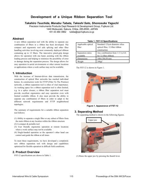
<strong>Development</strong> <strong>of</strong> a <strong>Unique</strong> <strong>Ribbon</strong> <strong>Separation</strong> <strong>Tool</strong>Takahiro Tsuchida, Manabu Tabata, Takeshi Sato, Shonosuke YaguchiPrecision Instruments Products Dept Research & <strong>Development</strong> Group, Fujikura Ltd.1440 Mutsuzaki, Sakura, Chiba, 285-8550, JAPAN+81 43 484 3962 tutida@opt.fujikura.co.jpAbstractA new ribbon separation tool with the ability to separate anycombination <strong>of</strong> fibers in a ribbon has been developed. Thecompact and ergonomic tool aids splicing and other fiberhandling activities involving most commonly deployed ribbonscontaining up to 12 fibers. The innovative pistol-grip designallows for operation with one hand, assisting with the ribbonloading process and helping to minimize the possibility <strong>of</strong> erroror damage during the separation process. The design allows foreasy operation in aerial environments or other remote locationsor applications where a work surface may not be available.1. IntroductionWith the increase <strong>of</strong> Internet-driven data transmission, theconstruction <strong>of</strong> optical fiber networks has reached individualhomes. In construction work for FTTP (Fiber To The Premise)networks, a ribbon separation tool is <strong>of</strong>ten <strong>of</strong> vital importance.As working space for a ribbon separation tool is <strong>of</strong>ten limited,e.g. in a splice closure, a ribbon fiber separation tool mustprovide excellent ergonomics and easy operation even withlimited available ribbon. It also must provide the ability toseparate any combination <strong>of</strong> fibers in order to adapt to thedifferent network requirements and FTTP neighborhoodtopologies.The summary <strong>of</strong> requirements for a suitable ribbon separationtool follows:(1) Ability to separate a single fiber or any subset <strong>of</strong> fibers fromthe main ribbon at any location within the ribbon structure(2) A compact & portable tool(3) User friendly ergonomic operation at remote locationswhere a work surface may not be available(4) Single-handed operation so the operator’s other hand cancontrol and guide the ribbon at all timesApplicable opticalfiber<strong>Separation</strong> ratiosavailableDimensionsWeightTable 1. FST-12 SpecificationsThe FST-12 is shown in Figure 1.Standard 125µm diameter silicaoptical fiber, 12-fiber ribbonconstructionAny combination from 1:11 to 6:6for 12-fiber ribbons160x130x30 mm240gfFigure 1. Appearance <strong>of</strong> FST-123. Separating MethodThe separating method is shown in the following figures.Upper jawTo meet these requirements, we have developed a completelynew ribbon separation tool with design and capabilitiesoptimized for flexible operation in difficult field conditions.2. Product OverviewFST-12 specifications are shown in Table 1.(1) Raise the upper jaw by pressing the thumb lever.International Wire & Cable Symposium 115 Proceedings <strong>of</strong> the 55th IWCS/Focus
Lower jaw(2) Place the fiber ribbon into the desired slot in the lower jaw<strong>of</strong> the tool.4. Separating PrincipleTo meet ribbon separation requirements, a shearing method isutilized. The ribbon is located vertically within the ribbonseparation tool, and shearing force is applied at the interfacebetween two adjacent fibers in order to provide separation <strong>of</strong>the ribbon at that particular location within the ribbon. Thereare six different slots into which they ribbon may be loaded intothe ribbon separation tool. Each slot provides a differentseparation ration (from 1:11 up to a 6:6 split). Since the ribboncan be loaded into any slot with either the #1 or the #12 fiber atthe top, these six slots provide the capability to split the ribbonbetween any two adjacent fibers.By repeating the shearing and separating process a second time,it is possible to separate a single fiber or subset <strong>of</strong> fibers fromwithin the main ribbon structure at any location. The outline <strong>of</strong>this method is shown in the three steps illustrated by the figuresthat follow. In the example shown, the ribbon is separated into2x2x8 sub-ribbon units.Upper jawTriggerSeparate(Shearing force)(3) Close the upper jaw, then pull and hold the trigger.Fiber ribbonLower jaw(4) Slide the tool down the length <strong>of</strong> the ribbon as the triggercontinues to be pulled to provide an appropriate ribbonseparation length.If it is only desired to separate a ribbon into two parts (forexample to shear-<strong>of</strong>f a single fiber or a sunset <strong>of</strong> fibers from anouter edge <strong>of</strong> the ribbon), the process is complete after steps (1)through (4) above. If a specific fiber or subset <strong>of</strong> fibers is tobe extracted from within the ribbon structure, steps (1) through(4) must be repeated in order to provide a separation on theother side <strong>of</strong> the target fiber or target sunset <strong>of</strong> fibers.(1) The ribbon is separated into a 2:10 ratio split by performingthe first shearing operation in the 2x10 slot. After pulling thetrigger to initiate the ribbon separation, either the ribbon istranslated laterally through the ribbon separation tool toextend the ribbon separation to the desired length, or the toolis translated down the ribbon until the desired separationlength is achieved.Fiber ribbonUpper jawLower jawSeparate(Shearing force)International Wire & Cable Symposium 116 Proceedings <strong>of</strong> the 55th IWCS/Focus
(2) The ribbon is placed back into the tool a second time. In thiscase, it is placed into the 4x8 slot. This second separationmust be initiated at a point just beyond the extent <strong>of</strong> theprevious separation (in an area where the ribbon structure iscompletely intact). In this case, the second shearingoperation provides a 4:8 separation split.150um in the spacing from fiber #1 to fiber #12 between ribbontype A and type D. This is quite a large difference, as itrepresents more than half the diameter <strong>of</strong> an individual250µm-coated fiber within a ribbon.(mm)3.5002.95 mm 3.10 mm0.15mm3.0002.5002.000Fiber ribbon1.5001.0000.5000.000Type A Type B Type C Type D(3) While continuing to hold the trigger in the “pulled” position,the 4:8 separation split is extended to overlap the length <strong>of</strong>ribbon separated into 2x10 sub-units in step (1). Thiscompletes an operation that splits the ribbon into2x2x8-fiber sub-ribbons, thereby allowing a 2-fiber subset <strong>of</strong>fibers to be extracted from within the ribbon for splicing,while maintaining the rest <strong>of</strong> the ribbon structure intact.5. Workability and ErgonomicsBy miniaturizing the tool overall, it is possible to provide asuitably portable tool useable in remote locations with easyoperation even with limited working space and limited ribbonlength available for access. Therefore, the tool is useable atFDH, ONT and FDT locations, as well as within fiber closuresand splice terminals.A pistol-grip tool design has been adopted. This allowsone-handed operation <strong>of</strong> the tool so the operator’s second handis free to guide the ribbon, load it into the proper tool slot, andremove the ribbon from the tool. This ensures that theoperator can control and protect the ribbon during the entireribbon separation process. This is critically important tooperations in remote locations where a work surface may not beavailable.6. Pertinent DetailsThe following are details <strong>of</strong> the ribbon separation tool.6.1 Conformity to ribbons from differentmanufacturersCommonly used fiber ribbons produced by differentmanufacturers vary in geometry and dimensions, as shown inFigure 2.The fiber-to-fiber pitch spacing is minimum for ribbon type A,and maximum for type D. There is a total difference <strong>of</strong> aboutFigure 2. Dimensions <strong>of</strong> common ribbon typesBecause the fiber pitch is different in the ribbons from eachmanufacturer, it was initially impossible to successfullyseparate ribbon types A through D with a single common ribbonseparation tool. The basic problem is that the ribbon separationslot for each splitting ratio must be the appropriate total height(upper + lower jaw heights) to accommodate the largest ribbonwidth. This presents a serious problem with the ribbon that hasthe narrowest total width.This problem is illustrated in Figure 3. In this case, the smallerribbon width does not completely fill the ribbon separation toolslot all the way from top to bottom, and a gap exists at the top<strong>of</strong> the upper jaw. Therefore, the shearing plane <strong>of</strong> the separationtool is not properly aligned at an intersection between twoadjacent fibers. In fact, the shearing location is almostperfectly aligned with the center <strong>of</strong> a fiber. Attempting aribbon separation in such a condition could result in severedamage to the fiber coating, and might even break the fibercompletely.Upper jawGap<strong>Separation</strong> grooveLower jawSeparateFigure 3. Improper location <strong>of</strong> the ribbon preventingproper separationInternational Wire & Cable Symposium 117 Proceedings <strong>of</strong> the 55th IWCS/Focus
In this situation, either a specific separation tool is required tomeet the dimensions <strong>of</strong> specific manufacturers’ ribbons, or atthe very least, interchangeable jaw sets are required to adjustthe slot depths for the ribbon to be separated. Either solutionis very inconvenient and confusing for the operator in the field.Excessive bending <strong>of</strong> the fibers during separation wasdetermined to result in the damage to the fibers. This isillustrated in Figure 6 below.Upper jawCylindrical shear edgeIn order to solve this problem, a novel design feature has beendeveloped. In the new design, a spring-loaded lifting rod appliesupwards force to the bottom <strong>of</strong> the fiber ribbon as illustrated inFigure 4. The lifting rod properly registers each ribbon withrespect to the upper (shearing) jaw <strong>of</strong> the ribbon separation tool.It is therefore possible to separate the commonly used ribbontypes A through D with a single ribbon separation tool with noneed to interchange or replace parts or jaw sets.Lift upLift upUpper jawLower jaw<strong>Separation</strong> grooveSeparateThe figure that viewed the crosssection from the top.Lift upLower jawLift upFigure 4. <strong>Ribbon</strong> separation shearing action6.2 Tensile strength <strong>of</strong> fibers before and afterseparationDuring the development <strong>of</strong> the separation tool, a prototyperibbon separation tool utilizing a cylindrical shearing edge wasfound to damage the fiber during separation from the ribbon.This is shown by the triangular data points in Figure 5 below.Break Probability (%)99.999905010510.50.110▲ After separation before optimizing● After separation after optimizing◆ Before separation20 30 40 50 60 70 80 90 100Tensile Strength (N)Figure 5. Tensile strength <strong>of</strong> fibers before and afterseparationLift upFigure 6. Excessive bending <strong>of</strong> the fiber beforeoptimizing the shearing edge shapeAfter optimizing the shape <strong>of</strong> shearing edge and adding thelifting rod, the break probability drastically improved (shown inthe circular data points in Figure 5). As the bending <strong>of</strong> the fiberduring separation with the new shearing edge design isnegligible, almost no fiber damage occurs. This is clearlyillustrated in Figure 5 by comparison <strong>of</strong> the strength <strong>of</strong> fibersseparated with the optimized shearing edge design to thestrength <strong>of</strong> pristine fibers that were not subjected to shearing(represented by the diamond data points). There is littledifference in the strength results. The greatly reduced bendingstress environment provided by the optimized design isillustrated in Figure 7 below.Upper jawLower jawLift upNew shearing edge<strong>Separation</strong> grooveThe figure that viewed the crosssection from the top.Figure 7. Reduced bending <strong>of</strong> the fiber afteroptimizing the shearing edge shapeInternational Wire & Cable Symposium 118 Proceedings <strong>of</strong> the 55th IWCS/Focus
The optimized production version <strong>of</strong> the ribbon separation tooltherefore has the capability to separate any combination <strong>of</strong>fibers from ribbons <strong>of</strong> up to 12 fibers with little change to thefiber strength and integrity.7. ConclusionThe new ribbon separation tool can provide dependable ribbonfiber separation operation in difficult FTTP operations. Itprovides complete flexibility in order to allow extraction <strong>of</strong> anyfiber or subset <strong>of</strong> fibers from the ribbon, and the tool’sergonomics and features provide user-friendly one-handedoperation to facilitate operation in a variety <strong>of</strong> locations in theabsence <strong>of</strong> any work surface. <strong>Separation</strong> operations can easilybe performed even with limited working space and withminimal accessible ribbon working length.AuthorsTakahiro TsuchidaPrecision InstrumentsProducts Dept R&D Group,Fujikura Ltd.1440 Mutsuzaki, Sakura,Chiba, 285-8550, JAPANtutida@opt.fujikura.co.jpTakeshi SatoPrecision InstrumentsProducts Dept R&D Group,Fujikura Ltd.1440 Mutsuzaki, Sakura,Chiba, 285-8550, JAPANtsatoh@opt.fujikura.co.jpTakeshi Sato received his mechanical engineering degree fromChiba University in 1984. He joined Fujikura Ltd. in 1984 andcurrently is an assistant manager <strong>of</strong> the Precision InstrumentsR&D department.Shonosuke YaguchiPrecision InstrumentsProducts Dept R&D Group,Fujikura Ltd.1440 Mutsuzaki, Sakura,Chiba, 285-8550, JAPANsyaguchi@fujikura.co.jpTakahiro Tsuchida received his M.M. degree in MechanicalEngineering from Chiba University in 2002. He joined FujikuraLtd. in 2002 and has been engaged in the research anddevelopment <strong>of</strong> optical fiber fusion splicers.Shonosuke Yaguchi received his mechanical engineering degreefrom Keio University in 1979. He joined Fujikura Ltd. in 1979and has been engaged in the Plant Engineering Section for 12years and currently is a general manager <strong>of</strong> the PrecisionInstruments Products Dept.Manabu TabataPrecision InstrumentsProducts Dept R&D Group,Fujikura Ltd.1440 Mutsuzaki, Sakura,Chiba, 285-8550, JAPANtabata@opt.fujikura.co.jpManabu Tabata received his mechanical engineering degreefrom Chiba University in 1999. He joined Fujikura Ltd. in 1999and has been engaged in the research and development <strong>of</strong>optical fiber fusion splicers.International Wire & Cable Symposium 119 Proceedings <strong>of</strong> the 55th IWCS/Focus