KI-62292 System 3000 Panel System Addendum AI 0111 ... - KI.com
KI-62292 System 3000 Panel System Addendum AI 0111 ... - KI.com
KI-62292 System 3000 Panel System Addendum AI 0111 ... - KI.com

Create successful ePaper yourself
Turn your PDF publications into a flip-book with our unique Google optimized e-Paper software.
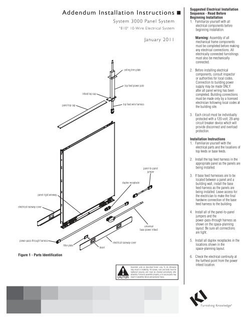
<strong>System</strong> <strong>3000</strong> <strong>Panel</strong> <strong>System</strong> - "810" 10-Wire Electrical <strong>System</strong><strong>Addendum</strong> Installation InstructionsAssemble units as described herein only. To do otherwisemay result in instability. All screws, nuts and bolts must betightened securely and must be checked periodically afterassembly. Failure to assemble properly, or to secure parts mayresult in assembly failure and personal injury.<strong>Panel</strong>-To-<strong>Panel</strong> ElectricalConnections 810-Universal1. Power is carried between adjacentpanels by panel jumpers (See DetailsA-F, for which jumper to use withdifferent panel configurations).2. Attach the panel jumpers to theplug-in ports that are on the end ofeach panel wireway by pushing themtogether until they are locked.3. If connecting power through anon-powered panel, plug the correctlength power-pass-through into theadjacent panel wireways(See Details G-J).4. Check the continuity frompanel-to-panel with a voltmeter.ACEGP10YOU USE:(1) 17” PANEL JUMPERYOU USE:(2) 17” PANEL JUMPERSYOU USE:(1) 20” PANEL JUMPERP10P10P10P10NPP10P10BP10YOU USE:(1) 17” PANEL JUMPERDFHP10YOU USE:(3) 17” PANEL JUMPERSP10NOTE:YOU MUST SPECIFY EITHERTHE 4-4-2 10-WIRE SYSTEM,OR THE 6-2-2 10-WIRESYSTEM. THE TWO SYSTEMSCANNOT BE MIXED.NPP10P10P10P10IP10NPYOU USE:(1) POWER-PASS-THROUGH THE SAMESIZE AS THE NON-POWERED PANELP10P10YOU USE: P10(1) POWER-PASS-THROUGH THE SAMESIZE AS THE NON-POWERED PANELJNPNPP10NPP10NPP10YOU USE:(1) POWER-PASS-THROUGH ONE SIZELARGER THAN THE NON-POWERED PANEL,(WITH EXCEPTION OF 60 NP PANELS)YOU USE:(1) POWER-PASS-THROUGH ONE SIZELARGER THAN THE NON-POWERED PANEL,(WITH EXCEPTION OF 60 NP PANELS)Details A - J2
<strong>System</strong> <strong>3000</strong> <strong>Panel</strong> <strong>System</strong> - "810" 10-Wire Electrical <strong>System</strong><strong>Addendum</strong> Installation InstructionsAssemble units as described herein only. To do otherwisemay result in instability. All screws, nuts and bolts must betightened securely and must be checked periodically afterassembly. Failure to assemble properly, or to secure parts mayresult in assembly failure and personal injury.rigid wirewayDuplex Receptacle Installation1. Duplex receptacles should beconnected after wireways are installedbut BEFORE power is connected tothe building supply.2. Follow the installation drawings toinstall the duplex receptacles forthe circuit desired in the correctlocations.3. Position the receptacle on either endof the wireway as shown (dependingon location desired), matching theN symbol to the same orientationon both the receptacle and wireway.4. Align the receptacle so the end isin line with the inner socket on thewireway (Figure 2).wirewayinner socket5. Push the receptacle back against themounting plate (Figure 2).duplex receptacle6. Slide the receptacle to the side so theend terminals slide into the wirewayinner socket (Figure 2).Figure 27. Receptacle is properly seated whenthe catch clip on the wirewayis between the wedges on thereceptacle.Removing Receptacle1. Slightly lift the catch clips on the topand bottom of the receptacle (Figure3) and slide the receptacle away fromthe socket on the wireway.2. Pull the receptacle away fromthe wireway once the end of thereceptacle clears the wireway socket.Note: Receptacles must be installedBEFORE raceway covers. Coversmust be removed to add, move, orchange receptacles.Caution: This step should be donewith great care. Do not insert ascrewdriver into electrical outlet. Donot remove the receptacle while it isunder load.3
<strong>System</strong> <strong>3000</strong> <strong>Panel</strong> <strong>System</strong> - "810" 10-Wire Electrical <strong>System</strong><strong>Addendum</strong> Installation InstructionsAssemble units as described herein only. To do otherwisemay result in instability. All screws, nuts and bolts must betightened securely and must be checked periodically afterassembly. Failure to assemble properly, or to secure parts mayresult in assembly failure and personal injury.Base Power Infeed InstallationCaution: The wires in the end of thebase feed power infeed must behard-wired later by an electrician. Itis not safe to perform the followingsteps if these wires are alreadyconnected to the building.universalbase power infeed1. Install the panel/base power infeedbefore the raceway cover is attached(Figure 3). If the raceway cover isalready installed, pull the cover outand up from the bottom.2. Determine from the layout whichpanel wireway will receive the powerfeed. Align the power feed the sameway you would a duplex receptacleif you were installing it in a rigidwireway (see previous page).3. Slide the power feed end terminalsinto place in the correspondingwireway inner socket. Press firmlyuntil both top and bottom springclips lock it in place.filler platebezelraceway cover4. Feed the conduit end of the powerfeed through the receptacle accessopening on the raceway cover. Installthe raceway cover on the panel base.Hook the raceway cover onto the tabson the two black support housing.Swing the raceway cover down untilit snaps into place.Figure 35. The base power infeeds arenon-handed (right-hand configurationis shown). The left or right refers tothe direction the conduit goes as youlook at the panel. The infeed will fit inany unused receptacle port at eitherend of a panel.6. To finish raceway cover assembly,insert filler plate(s) into unusedbezels (Figure 3).4
<strong>System</strong> <strong>3000</strong> <strong>Panel</strong> <strong>System</strong> - "810" 10-Wire Electrical <strong>System</strong><strong>Addendum</strong> Installation InstructionsAssemble units as described herein only. To do otherwisemay result in instability. All screws, nuts and bolts must betightened securely and must be checked periodically afterassembly. Failure to assemble properly, or to secure parts mayresult in assembly failure and personal injury.infeedtop captopinfeed poleTop Power Infeed InstallationCaution: The wires in the loose endof the top power infeed must behard-wired later by an electrician.It is not safe to perform any of thefollowing steps if these wires arealready connected.1. Snap the infeed top cap in place.3. Place the top infeed pole nextto the panel so that the top ofthe pole touches the ceiling.Mark a point 4" longer thanthe distance from the top ofthe trim cap to the ceiling. Usea hacksaw to cut the pole atthis point (Figure 4). Be sureall burrs or sharp edges areremoved after cutting.Figure 4top infeedharnessFigure 5ceilingtrim platetopinfeed polepanelsidewirewayNote: Before measuring the pole, becertain the panel is level and in itsfinal location.2. Drop a plumb line from the ceilingto a corner of the rectangular hole inthe top infeed trim cap. At the ceiling,mark a 2 5 / 8" x 1 1 / 2" hole starting atthe same corner. The 2 5 / 8" dimensioncorresponds to the direction of thepanel run. Cut out the hole in theceiling tile.4. If you did not do so in thepanel prep, feed the top infeedharness conduit up the panelside wireway from the bottom ofthe panel (Figure 5). Guide theconduit through the top infeedtrim cap when it reaches thetop of the panel. In the racewayof the panel, plug the femaleterminal on the top power infeedinto the male terminal of therigid wireway.5. Slide a ceiling trim plate aroundthe top of the top infeed pole.Feed the top infeed harnessconduit through the smallchannel of the top infeed pole.When the conduit has reachedthe top of the pole, guide thepole into the hole in the ceiling.Continue to feed the conduitinto the bottom of the pole untilthe top infeed pole can be setinto the hole in the top infeedtrim cap (Figure 6).Figure 6infeedtop cap6. Slide the trim plate up the topinfeed pole until it is tightagainst the ceiling.For Electrician’s ReferenceTo reach the infeed conduit for hardwiringabove the ceiling, removeadjacent ceiling tile. Communicationcables may be fed down the largerchannel of the top infeed pole at alater time.5
<strong>System</strong> <strong>3000</strong> <strong>Panel</strong> <strong>System</strong> - "810" 10-Wire Electrical <strong>System</strong><strong>Addendum</strong> Installation InstructionsAssemble units as described herein only. To do otherwisemay result in instability. All screws, nuts and bolts must betightened securely and must be checked periodically afterassembly. Failure to assemble properly, or to secure parts mayresult in assembly failure and personal injury.Power Infeed to BuildingConnectionHave a certified electrician hard-wirethe panel power infeed to the buildingpower source according to the NationalElectrical Code and any other applicablelocal codes. See the chart for properwiring connection to available power.ReceptaclesavailableCircuit 1Circuit 24-4-2Wires to be usedBlackWhite/Black LettersGreen or BareRedWhite/Black LettersGreen or BareGauge ofwire121212121212Circuit 3BlueWhite/Black LettersGreen/Yellow Stripeor Gray121212Circuit 4PinkWhite/Purple LettersGreen/Yellow Stripeor Gray1212124-4-2 Connection Diagrams120/240V SINGLE PHASECIR. 1CIR. 2DEAD METALBLACK (LINE 1)BLUE (LINE 3)WHITE/BLACK (NEUTRAL 1)WHITE/BLUE (NEUTRAL 3)GREEN OR BARE (GROUND 1 & 2)GREEN/YELLOW OR GRAY (ISOLATED GROUND 3 & 4)WHITE/RED (NEUTRAL 2)WHITE/PURPLE (NEUTRAL 4)RED (LINE 2)PINK (LINE 4)CIR. 3CIR. 4120/208V WYE (THREE PHASE)CIR. 1CIR. 2DEAD METALBLACK (LINE 1)BLUE (LINE 3)WHITE/BLACK (NEUTRAL 1)WHITE/BLUE (NEUTRAL 3)GREEN OR BARE (GROUND 1 & 2)GREEN/YELLOW OR GRAY (ISOLATED GROUND 3 & 4)WHITE/RED (NEUTRAL 2)WHITE/PURPLE (NEUTRAL 4)RED (LINE 2)PINK (LINE 4)CIR. 3 CIR. 46
<strong>System</strong> <strong>3000</strong> <strong>Panel</strong> <strong>System</strong> - "810" 10-Wire Electrical <strong>System</strong><strong>Addendum</strong> Installation InstructionsAssemble units as described herein only. To do otherwisemay result in instability. All screws, nuts and bolts must betightened securely and must be checked periodically afterassembly. Failure to assemble properly, or to secure parts mayresult in assembly failure and personal injury.6-2-2 Connection Diagrams120/240V SINGLE PHASEBLACK (LINE 1)PINK (LINE 4)WHITE/RED (NEUTRAL 4,5)GREEN/YELLOW OR GRAY (ISOLATED GROUND 4,5)GREEN OR BARE (GROUND 1,2)WHITE/BLACK (NEUTRAL 1,2)RED (LINE 2)TAN (LINE 5)DO NOT CONNECT BLUE (LINE 3)DO NOT CONNECT ORANGE (LINE 6)CIR. 1 CIR. 2CIR. 3DEAD METAL810-Universal Wire ConnectionDiagramsHave a certified electrician hard-wirethe panel power infeed to the buildingpower source according to the NationalElectrical Code and any other applicablelocal codes. See the chart for properwiring connection to available power.6-2-2120/208V WYE (THREE PHASE)BLACK (LINE 1)PINK (LINE 4)WHITE/RED (NEUTRAL 4,5 & 6)GREEN/YELLOW OR GRAY (ISOLATED GROUND 4,5 & 6)GREEN OR BARE (GROUND 1,2 & 3)WHITE/BLACK (NEUTRAL 1,2 & 3)RED (LINE 2)TAN (LINE 5)BLUE (LINE 3)ORANGE (LINE 6)CIR. 1CIR. 4 CIR. 5 CIR. 6CIR. 2 CIR. 3DEAD METALReceptaclesavailableCircuit 1Circuit 2Circuit 3Wires to be usedBlackWhite/Black LettersGreen or BareRedWhite/Black LettersGreen or BareBlueWhite/Black LettersGreen or BareGaugeof wire1210121210121210126-2-2 Connection Diagrams To An 8-Wire Building120/240V SINGLE PHASEBLACK (LINE 1)PINK (LINE 4)WHITE/RED (NEUTRAL 4)GREEN/YELLOW OR GRAY (ISOLATED GROUND 4)GREEN OR BARE (GROUND 1,2)WHITE/BLACK (NEUTRAL 1,2)DO NOT CONNECT RED (LINE 2)DO NOT CONNECT TAN (LINE 5)BLUE (LINE 3)DO NOT CONNECT ORANGE (LINE 6)CIR. 4 CIR. 5 CIR. 6CIR. 1 CIR. 2CIR. 3DEAD METALCircuit 4ICircuit 5ICircuit 6IPinkWhite/Purple LettersGreen/Yellow Stripeor GrayTanWhite/Red LettersGreen/Yellow Stripeor GrayOrangeWhite/Red LettersGreen/Yellow Stripeor Gray121012121012121012CIR. 4 CIR. 5 CIR. 6120/208V WYE (THREE PHASE)CIR. 1CIR. 2 CIR. 3DEAD METALBLACK (LINE 1)PINK (LINE 4)WHITE/RED (NEUTRAL 4)GREEN/YELLOW OR GRAY (ISOLATED GROUND 4)GREEN OR BARE (GROUND 1,2 & 3)WHITE/BLACK (NEUTRAL 1,2 & 3)RED (LINE 2)DO NOT CONNECT TAN (LINE 5)BLUE (LINE 3)DO NOT CONNECT ORANGE (LINE 6)CIR. 4 CIR. 5 CIR. 67
<strong>KI</strong>1330 Bellevue StreetP.O. Box 8100Green Bay, Wisconsin 54308-81001-800-424-2432www.ki.<strong>com</strong><strong>KI</strong> is a registered trademarkof Krueger International, Inc.© 2011 <strong>KI</strong>All Rights ReservedLitho in USA.Code <strong>KI</strong>-<strong>62292</strong>/HT/GT/<strong>0111</strong>