Study of Water Distribution Network Using EPANET - ijcer
Study of Water Distribution Network Using EPANET - ijcer
Study of Water Distribution Network Using EPANET - ijcer
- No tags were found...
Create successful ePaper yourself
Turn your PDF publications into a flip-book with our unique Google optimized e-Paper software.
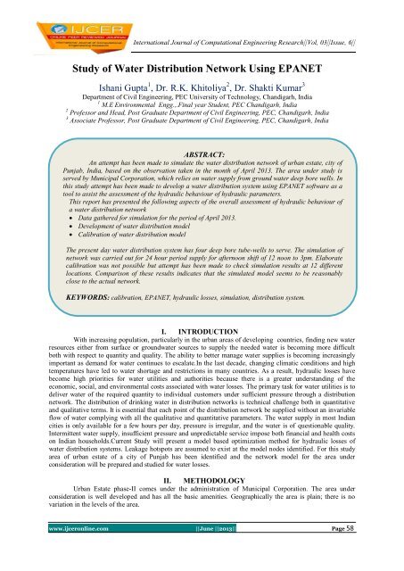
International Journal <strong>of</strong> Computational Engineering Research||Vol, 03||Issue, 6||<strong>Study</strong> <strong>of</strong> <strong>Water</strong> <strong>Distribution</strong> <strong>Network</strong> <strong>Using</strong> <strong>EPANET</strong>Ishani Gupta 1 , Dr. R.K. Khitoliya 2 , Dr. Shakti Kumar 3Department <strong>of</strong> Civil Engineering, PEC University <strong>of</strong> Technology, Chandigarh, India1 M.E Environmental Engg.,.Final year Student, PEC Chandigarh, India2 Pr<strong>of</strong>essor and Head, Post Graduate Department <strong>of</strong> Civil Engineering, PEC, Chandigarh, India3 Associate Pr<strong>of</strong>essor, Post Graduate Department <strong>of</strong> Civil Engineering, PEC, Chandigarh, IndiaABSTRACT:An attempt has been made to simulate the water distribution network <strong>of</strong> urban estate, city <strong>of</strong>Punjab, India, based on the observation taken in the month <strong>of</strong> April 2013. The area under study isserved by Municipal Corporation, which relies on water supply from ground water deep bore wells. Inthis study attempt has been made to develop a water distribution system using <strong>EPANET</strong> s<strong>of</strong>tware as atool to assist the assessment <strong>of</strong> the hydraulic behaviour <strong>of</strong> hydraulic parameters.This report has presented the following aspects <strong>of</strong> the overall assessment <strong>of</strong> hydraulic behaviour <strong>of</strong>a water distribution network Data gathered for simulation for the period <strong>of</strong> April 2013. Development <strong>of</strong> water distribution model Calibration <strong>of</strong> water distribution modelThe present day water distribution system has four deep bore tube-wells to serve. The simulation <strong>of</strong>network was carried out for 24 hour period supply for afternoon shift <strong>of</strong> 12 noon to 3pm. Elaboratecalibration was not possible but attempt has been made to check simulation results at 12 differentlocations. Comparison <strong>of</strong> these results indicates that the simulated model seems to be reasonablyclose to the actual network.KEYWORDS: calibration, <strong>EPANET</strong>, hydraulic losses, simulation, distribution system.I. INTRODUCTIONWith increasing population, particularly in the urban areas <strong>of</strong> developing countries, finding new waterresources either from surface or groundwater sources to supply the needed water is becoming more difficultboth with respect to quantity and quality. The ability to better manage water supplies is becoming increasinglyimportant as demand for water continues to escalate.In the last decade, changing climatic conditions and hightemperatures have led to water shortage and restrictions in many countries. As a result, hydraulic losses havebecome high priorities for water utilities and authorities because there is a greater understanding <strong>of</strong> theeconomic, social, and environmental costs associated with water losses. The primary task for water utilities is todeliver water <strong>of</strong> the required quantity to individual customers under sufficient pressure through a distributionnetwork. The distribution <strong>of</strong> drinking water in distribution networks is technical challenge both in quantitativeand qualitative terms. It is essential that each point <strong>of</strong> the distribution network be supplied without an invariableflow <strong>of</strong> water complying with all the qualitative and quantitative parameters. The water supply in most Indiancities is only available for a few hours per day, pressure is irregular, and the water is <strong>of</strong> questionable quality.Intermittent water supply, insufficient pressure and unpredictable service impose both financial and health costson Indian households.Current <strong>Study</strong> will present a model based optimization method for hydraulic losses <strong>of</strong>water distribution systems. Leakage hotspots are assumed to exist at the model nodes identified. For this studyarea <strong>of</strong> urban estate <strong>of</strong> a city <strong>of</strong> Punjab has been identified and the network model for the area underconsideration will be prepared and studied for water losses.II. METHODOLOGYUrban Estate phase-II comes under the administration <strong>of</strong> Municipal Corporation. The area underconsideration is well developed and has all the basic amenities. Geographically the area is plain; there is novariation in the levels <strong>of</strong> the area.www.<strong>ijcer</strong>online.com ||June ||2013|| Page 58
<strong>Study</strong> Of <strong>Water</strong> <strong>Distribution</strong>...2.1.Data Collection[1] <strong>Distribution</strong> network drawing- A copy <strong>of</strong> the drawing <strong>of</strong> the existing distribution system was takenfrom the Municipal Corporation. The drawing helps in the understanding <strong>of</strong> the distribution <strong>of</strong> themains, sub-mains, how they move in the area, presence <strong>of</strong> dead ends etc.[2] Source data- Ground water is the main source <strong>of</strong> water. The ground water table is present at a depth <strong>of</strong>250 ft.[3] Four tube-wells are used to pump out the water for the drinking water supply. The pumping capacity,head and other required data regarding them was taken from the municipal corporation.[4] Topography- Although the elevations <strong>of</strong> the area were present with corporation <strong>of</strong>fice, it was decidedto go through the level measurements again to better understand the topography <strong>of</strong> the area. Theequipments used for level measurements werea) Auto levelb) staff.The measurements were taken in the following manner starting from tube-well no 1 covering tube-wellno. 2 and 3 and the whole area along with tube-well no. 4 in the end.It was not an easy task to move through the busy streets <strong>of</strong> the area. Therefore, there was lot <strong>of</strong> shiftingin the auto level positions, which led to increase in the foresight and backsight readings and increase inthe calculation work. With so much shifting in the instrument positions there is always the chance <strong>of</strong>occurrence <strong>of</strong> errors but utmost care was taken to reduce the possibility <strong>of</strong> error occurrence.[5] Population data- As per the census <strong>of</strong> 2011, the population <strong>of</strong> the urban estate is 9150 persons. Thetotal population was available with the municipal corporation.Now, when all the data collection work was done, the first job was to draw the computer aided model.The model was prepared on the <strong>EPANET</strong> s<strong>of</strong>tware.[6] <strong>Distribution</strong> system- The distribution system itself is a complex network <strong>of</strong> transmission mains,distribution pipelines and pumping stations. The mains and sub mains has the size ranging from200mm, 150mm and 100mm along with small house connection pipes.[7] Pumping stations- There are four tube-wells used for supply <strong>of</strong> drinking water to the village, namelytube-well no.1, 2, 3 and 4 respectively. Ground water is the main source <strong>of</strong> water. Each pumpingstation is equipped with a pressure gauge for documentation <strong>of</strong> the pump gauge.Preparation <strong>of</strong> the modelFrom the original drawing <strong>of</strong> the distribution network provided by the municipal corporation, thedistribution network was reproduced on the graph paper. It was difficult to mark every house on thegraph sheet and then on the model. So the whole network was divided into different junctions whereeach junction represents a definite set <strong>of</strong> houses. Each junction is given a serial no. j1, j2, j3 etc. X-Yco-ordinates were given to all the junctions <strong>of</strong> the network, which were needed for computer aidedmodel.After marking <strong>of</strong> the junctions, the co-ordinates <strong>of</strong> all the junctions were noted down from the graphsheet. In similar fashion the elevations which were measured earlier as per junction locations, werenoted down on the separate plain sheet but as there was hardly any variation in the elevations <strong>of</strong>different junctions so we considered all the elevations to be equal and marked it levelled one in alljunctions. Next job was to draw these junctions on the <strong>EPANET</strong> s<strong>of</strong>tware and then assigning them therequired properties calculated above, in the properties box <strong>of</strong> each junction.For creating an <strong>EPANET</strong> model following network elements were used-:[1] Junctions[2] Pumps[3] Valves[4] Reservoirs[5] PipesTo draw the network X-Y co-ordinates limits were set up in the s<strong>of</strong>tware from the graph sheet. First <strong>of</strong>all, all the junctions were put in model in serial order from the tool box <strong>of</strong> the s<strong>of</strong>tware and then their requiredproperties were assigned to them.Similarly, other major points like the reservoirs representing groundwater andpumps were drawn on the network with their required properties.After marking <strong>of</strong> all the major points andincorporation <strong>of</strong> all the required data on the computer aided model these points were then joined together by thelines representing pipes. The pipe data like the pipe roughness, pipe diameter etc was provided in the propertybox <strong>of</strong> all the pipes.www.<strong>ijcer</strong>online.com ||June ||2013|| Page 59
<strong>Study</strong> Of <strong>Water</strong> <strong>Distribution</strong>...Static period analysis-When sufficient data was incorporated in the computer aided network model,next job was to run it for the static period analysis. The static period analysis was done to check that whether thedata provided was correct and sufficient. Calibration <strong>of</strong> equipment -Well in advance <strong>of</strong> the field tests, all theequipments being used should be checked and recalibrated. Before taking the pressure gauges for fieldmeasurements they were calibrated. The gauges were found to be accurate.Pressure Measurements- For pressuremeasurements the pressure gauges <strong>of</strong> different ranges were used. These gauges were then installed at differentlocations to physically measure the pressure heads <strong>of</strong> tube-wells.After the pressure measurements <strong>of</strong> the tubewells,the pressure heads at the different junctions <strong>of</strong> the distribution network were to be carried out for thecalibration purpose. The junctions were selected as per their location from the pumping stations. The pressurereadings were taken on 15 th April 2013 at 1pm. The supply hours in the area under study are 10 hrs spanningthree shifts. The first shift is from 5 am to 9 am, 2 nd shift from 12 noon to 3 pm and third shift from 6 pm to 9pm.Calibration work- After the job <strong>of</strong> pressure measurements, the model was calibrated for hydraulic analysis.There is a provision for the single stage simulation and the extended period simulation in the s<strong>of</strong>tware. Themodel was calibrated for the extended period simulation. The results <strong>of</strong> the analysis and required discussion aregiven in the next chapter.III. RESULTS AND DISCUSSIONNode Results-Ministry Of Urban Development (Govt. <strong>of</strong> India) manual on water supply stipulates aminimum residual pressure <strong>of</strong> 7m, 12m and 17m for single storey, double storey and triple storey buildingsrespectively at the end <strong>of</strong> design period. But the results are not attained even during the initial periods <strong>of</strong>commissioning. The residual pressure were checked at few points and found to be very low and rangingbetween 2m to 5m at the middle and far <strong>of</strong>f points from the pumping stations in the area at the time <strong>of</strong>measurement. It clearly shows that the system is under performing and that the desired level <strong>of</strong> service is notachieved for residual pressure requirements. The s<strong>of</strong>tware model results for pressure closely match with thefield measurements and is shown in table I.Pipe Results- With available infrastructure <strong>of</strong> water supply it is onlypossible to measure the velocity and flow in pipes. No work was undertaken for the measurement <strong>of</strong> „c‟ valueand these were changed to match the field measurement values for flow in a pipe. From analysis <strong>of</strong> the watersupply network it is clear that the carrying capacities <strong>of</strong> pipes are sufficient to serve the present requirement andmay serve for many years to come.TABLE NO. 1CALIBRATION RESULTS-PRESSURESr. Node No. Pressure as per fieldNo.measurement(m)1 J13 3.78 4.002 J31 3.24 3.663 J42 3.29 3.524 J57 2.98 3.485 J66 3.02 3.596 J83 3.72 3.697 J87 3.37 3.808 J100 4.02 4.089 J103 3.73 4.1110 J125 3.96 4.1411 J168 4.08 4.2612 J197 3.29 3.57Pressure as per IntermittentEPS Model(m)IV. CONCLUSIONIn this study attempt has been made to develop a water distribution system using <strong>EPANET</strong> s<strong>of</strong>tware asa tool to assist the assessment <strong>of</strong> the hydraulic behaviour <strong>of</strong> water supply distribution network.This report has presented the following aspects <strong>of</strong> the overall assessment <strong>of</strong> hydraulic behaviour <strong>of</strong> a waterdistribution network Data gathered for simulation for the period <strong>of</strong> April 2013. Development <strong>of</strong> water distribution model Calibration <strong>of</strong> water distribution modelThe present day water distribution system has four deep bore tube-wells to serve. The simulation <strong>of</strong>network was carried out for 24 hour period supply for afternoon shift <strong>of</strong> 12 noon to 3pm. Elaborate calibrationwas not possible but attempt has been made to check simulation results at 10 different locations. Comparison <strong>of</strong>these results indicates that the simulated model seems to be reasonably close to the actual network.www.<strong>ijcer</strong>online.com ||June ||2013|| Page 60
<strong>Study</strong> Of <strong>Water</strong> <strong>Distribution</strong>...ACKNOWLEDGEMENTSThe authors are grateful to PEC University <strong>of</strong> Technology, Chandigarh for their cooperation andencouragement to carry out the work.REFERENCES[1] Morris L. Maslia: Jason B Sautner Mustafa M Aral “Analysis <strong>of</strong> 1998 water distribution system serving the Dover TownshipArea, New Jersey : Fielad Data Collection Activities and <strong>Water</strong> <strong>Distribution</strong> System Modeling” Agency for Toxic Substancesand Disease Registry, U S Department <strong>of</strong> Health and Human Services, Atlanta, Georgia, June 2000.[2] <strong>EPANET</strong> 2, Users Manual : United States Environmental Protection Agency EPA/600/R-00/057 Sep 2000 available on internetat: http://www.epa.gov/ORD/NRMRL/wswrd/epanet.html[3] Richard N. Stalford, Jasquiline : “<strong>Water</strong> <strong>Distribution</strong> Modeling , G I S and Facility Management Systems, what do they have incommon? A Case <strong>Study</strong>” available on World Wide Web.[4] Guillermo Yepes, Klas Ringskog and Shyamal sarkar (2001): The High Cost <strong>of</strong> Intermittent Service, Journal <strong>of</strong> Indian <strong>Water</strong>Works Association (IWWA), April-June 2001.[5] N. Sashikumar : Proceedings <strong>of</strong> Annual Conference Of ASCE and Environmental <strong>Water</strong> Resource Institute(EWRI), June 22-26,2003, Philadelphia, USA.[6] Rajiv Batish : Proceedings <strong>of</strong> Annual Conference Of ASCE and Environmental <strong>Water</strong> Resource Institute (EWRI), June 22-26,2003, Philadelphia, USA.[7] Puli Venkateshwara Rao : Manual for Intermediate Vocational Course, 1st Year : WATER SUPPLY ENGINEERING (For theCourse <strong>of</strong> <strong>Water</strong> Supply and Sanitary Engineering), State Institute <strong>of</strong> Vocational Education Andhra Pradesh. Hyderabad, 2005.www.<strong>ijcer</strong>online.com ||June ||2013|| Page 61


