QoS Performance Evaluation in BGP/MPLS VPN
QoS Performance Evaluation in BGP/MPLS VPN
QoS Performance Evaluation in BGP/MPLS VPN

You also want an ePaper? Increase the reach of your titles
YUMPU automatically turns print PDFs into web optimized ePapers that Google loves.
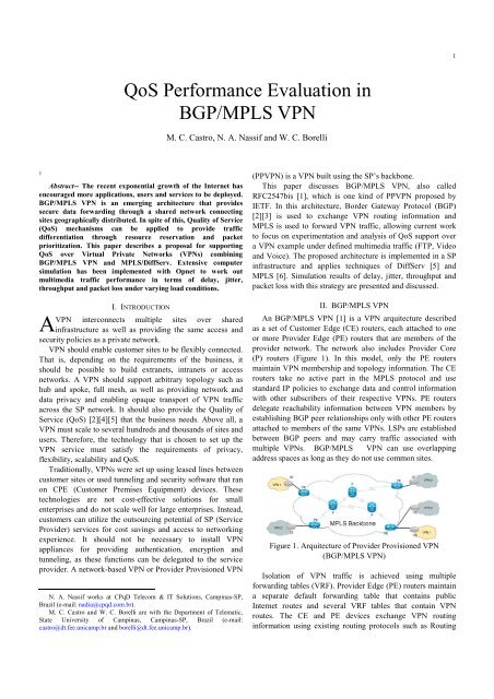
1<strong>QoS</strong> <strong>Performance</strong> <strong>Evaluation</strong> <strong>in</strong><strong>BGP</strong>/<strong>MPLS</strong> <strong>VPN</strong>M. C. Castro, N. A. Nassif and W. C. Borelli1Abstract-- The recent exponential growth of the Internet hasencouraged more applications, users and services to be deployed.<strong>BGP</strong>/<strong>MPLS</strong> <strong>VPN</strong> is an emerg<strong>in</strong>g architecture that providessecure data forward<strong>in</strong>g through a shared network connect<strong>in</strong>gsites geographically distributed. In spite of this, Quality of Service(<strong>QoS</strong>) mechanisms can be applied to provide trafficdifferentiation through resource reservation and packetprioritization. This paper describes a proposal for support<strong>in</strong>g<strong>QoS</strong> over Virtual Private Networks (<strong>VPN</strong>s) comb<strong>in</strong><strong>in</strong>g<strong>BGP</strong>/<strong>MPLS</strong> <strong>VPN</strong> and <strong>MPLS</strong>/DiffServ. Extensive computersimulation has been implemented with Opnet to work outmultimedia traffic performance <strong>in</strong> terms of delay, jitter,throughput and packet loss under vary<strong>in</strong>g load conditions.AI. INTRODUCTION<strong>VPN</strong> <strong>in</strong>terconnects multiple sites over shared<strong>in</strong>frastructure as well as provid<strong>in</strong>g the same access andsecurity policies as a private network.<strong>VPN</strong> should enable customer sites to be flexibly connected.That is, depend<strong>in</strong>g on the requirements of the bus<strong>in</strong>ess, itshould be possible to build extranets, <strong>in</strong>tranets or accessnetworks. A <strong>VPN</strong> should support arbitrary topology such ashub and spoke, full mesh, as well as provid<strong>in</strong>g network anddata privacy and enabl<strong>in</strong>g opaque transport of <strong>VPN</strong> trafficacross the SP network. It should also provide the Quality ofService (<strong>QoS</strong>) [2][4][5] that the bus<strong>in</strong>ess needs. Above all, a<strong>VPN</strong> must scale to several hundreds and thousands of sites andusers. Therefore, the technology that is chosen to set up the<strong>VPN</strong> service must satisfy the requirements of privacy,flexibility, scalability and <strong>QoS</strong>.Traditionally, <strong>VPN</strong>s were set up us<strong>in</strong>g leased l<strong>in</strong>es betweencustomer sites or used tunnel<strong>in</strong>g and security software that ranon CPE (Customer Premises Equipment) devices. Thesetechnologies are not cost-effective solutions for smallenterprises and do not scale well for large enterprises. Instead,customers can utilize the outsourc<strong>in</strong>g potential of SP (ServiceProvider) services for cost sav<strong>in</strong>gs and access to network<strong>in</strong>gexperience. It should not be necessary to <strong>in</strong>stall <strong>VPN</strong>appliances for provid<strong>in</strong>g authentication, encryption andtunnel<strong>in</strong>g, as these functions can be delegated to the serviceprovider. A network-based <strong>VPN</strong> or Provider Provisioned <strong>VPN</strong>N. A. Nassif works at CPqD Telecom & IT Solutions, Camp<strong>in</strong>as-SP,Brazil (e-mail: nadia@cpqd.com.br).M. C. Castro and W. C. Borelli are with the Department of Telematic,State University of Camp<strong>in</strong>as, Camp<strong>in</strong>as-SP, Brazil (e-mail:castro@dt.fee.unicamp.br and borelli@dt.fee.unicamp.br).(PP<strong>VPN</strong>) is a <strong>VPN</strong> built us<strong>in</strong>g the SP’s backbone.This paper discusses <strong>BGP</strong>/<strong>MPLS</strong> <strong>VPN</strong>, also calledRFC2547bis [1], which is one k<strong>in</strong>d of PP<strong>VPN</strong> proposed byIETF. In this architecture, Border Gateway Protocol (<strong>BGP</strong>)[2][3] is used to exchange <strong>VPN</strong> rout<strong>in</strong>g <strong>in</strong>formation and<strong>MPLS</strong> is used to forward <strong>VPN</strong> traffic, allow<strong>in</strong>g current workto focus on experimentation and analysis of <strong>QoS</strong> support overa <strong>VPN</strong> example under def<strong>in</strong>ed multimedia traffic (FTP, Videoand Voice). The proposed architecture is implemented <strong>in</strong> a SP<strong>in</strong>frastructure and applies techniques of DiffServ [5] and<strong>MPLS</strong> [6]. Simulation results of delay, jitter, throughput andpacket loss with this strategy are presented and discussed.II. <strong>BGP</strong>/<strong>MPLS</strong> <strong>VPN</strong>An <strong>BGP</strong>/<strong>MPLS</strong> <strong>VPN</strong> [1] is a <strong>VPN</strong> arquitecture describedas a set of Customer Edge (CE) routers, each attached to oneor more Provider Edge (PE) routers that are members of theprovider network. The network also <strong>in</strong>cludes Provider Core(P) routers (Figure 1). In this model, only the PE routersma<strong>in</strong>ta<strong>in</strong> <strong>VPN</strong> membership and topology <strong>in</strong>formation. The CErouters take no active part <strong>in</strong> the <strong>MPLS</strong> protocol and usestandard IP policies to exchange data and control <strong>in</strong>formationwith other subscribers of their respective <strong>VPN</strong>s. PE routersdelegate reachability <strong>in</strong>formation between <strong>VPN</strong> members byestablish<strong>in</strong>g <strong>BGP</strong> peer relationships only with other PE routersattached to members of the same <strong>VPN</strong>s. LSPs are establishedbetween <strong>BGP</strong> peers and may carry traffic associated withmultiple <strong>VPN</strong>s. <strong>BGP</strong>/<strong>MPLS</strong> <strong>VPN</strong> can use overlapp<strong>in</strong>gaddress spaces as long as they do not use common sites.Figure 1. Arquitecture of Provider Provisioned <strong>VPN</strong>(<strong>BGP</strong>/<strong>MPLS</strong> <strong>VPN</strong>)Isolation of <strong>VPN</strong> traffic is achieved us<strong>in</strong>g multipleforward<strong>in</strong>g tables (VRF). Provider Edge (PE) routers ma<strong>in</strong>ta<strong>in</strong>a separate default forward<strong>in</strong>g table that conta<strong>in</strong>s publicInternet routes and several VRF tables that conta<strong>in</strong> <strong>VPN</strong>routes. The CE and PE devices exchange <strong>VPN</strong> rout<strong>in</strong>g<strong>in</strong>formation us<strong>in</strong>g exist<strong>in</strong>g rout<strong>in</strong>g protocols such as Rout<strong>in</strong>g
2Information Protocol (RIP), OSPF and <strong>BGP</strong>. Routes learnedare <strong>in</strong>stalled <strong>in</strong> the correspond<strong>in</strong>g VRF table(s) based on therout<strong>in</strong>g protocol’s decision process. At the PE device, the<strong>VPN</strong> routes, that were determ<strong>in</strong>ed from the attached CEdevices, are <strong>in</strong>stalled <strong>in</strong> VRF tables and the PE devices mustexchange these routes with other PE devices. Multiprotocol<strong>BGP</strong> (MP-<strong>BGP</strong>) [3] is used to distribute <strong>VPN</strong> routes to otherPE devices across the SP network. S<strong>in</strong>ce <strong>VPN</strong>s can useoverlapp<strong>in</strong>g address spaces, <strong>BGP</strong> may determ<strong>in</strong>e routes todest<strong>in</strong>ations with the same address prefix.The concept of Label Stack<strong>in</strong>g (known as hierarchy oflabels) is used when build<strong>in</strong>g <strong>BGP</strong>/<strong>MPLS</strong> <strong>VPN</strong>. The <strong>in</strong>gressrouter appends two labels to a packet belong<strong>in</strong>g to a <strong>VPN</strong>. The<strong>in</strong>ner label specifies the egress port at the SP egress router (thel<strong>in</strong>k toward the dest<strong>in</strong>ation sub-network of the <strong>VPN</strong>) and theouter label is be<strong>in</strong>g used to forward the packet toward theegress router. With MP-<strong>BGP</strong>, the <strong>in</strong>gress router works out the<strong>in</strong>ner label <strong>in</strong>formation, and the outer label data is ga<strong>in</strong>ed by<strong>MPLS</strong> signal<strong>in</strong>g protocols such as CR-LDP [7] or RSVP-TE[8]. The egress router pops both labels.One of the benefits of us<strong>in</strong>g <strong>BGP</strong>/<strong>MPLS</strong> <strong>VPN</strong> is that the SPbackbone does not need any protocol software upgrades andcan function as it is. This is because the P routers are not <strong>VPN</strong>aware. The <strong>VPN</strong> routes are exchanged between PE devicesand the P routers are unaware of these routes. However, thismeans that <strong>VPN</strong> traffic must be forwarded opaquely across theSP backbone and that the <strong>VPN</strong> traffic must be tunneled acrossthe network. This is achieved by sett<strong>in</strong>g up <strong>MPLS</strong> tunnelsbetween the PE devices.III. SUPPORT OF QOS FOR <strong>VPN</strong>The provision of Quality of Service (<strong>QoS</strong>) is an <strong>in</strong>tr<strong>in</strong>sicpart of emerg<strong>in</strong>g services centered on provider-provisioned<strong>VPN</strong>s (PP<strong>VPN</strong>s). One solution to provide <strong>QoS</strong> functionality to<strong>BGP</strong>/<strong>MPLS</strong> <strong>VPN</strong>s is to implement an <strong>MPLS</strong>/DiffServ<strong>in</strong>teroperation at the core of network.<strong>MPLS</strong> and DiffServ [9] can be applied together as theyhave some similar features that permit them to be<strong>in</strong>teroperable. Both technologies perform packet classificationonly <strong>in</strong> the <strong>in</strong>gress edge router (LER), consider<strong>in</strong>g that bothconsider aggregated classes of traffic: <strong>MPLS</strong> with FECs andDiffServ with PHBs.Short fixed length labels are used <strong>in</strong> both networks, whichare called <strong>MPLS</strong> labels <strong>in</strong> <strong>MPLS</strong> networks and DSCPs <strong>in</strong>DiffServ networks. Routers <strong>in</strong> the core network treat thepackets accord<strong>in</strong>g to these tags and the DSCP of a packetdeterm<strong>in</strong>es the behaviors of the nodes regard<strong>in</strong>g schedul<strong>in</strong>gmechanisms and queu<strong>in</strong>g management. This typically def<strong>in</strong>esthe priority and the drop precedence of the packets.The <strong>MPLS</strong> label of a packet determ<strong>in</strong>es the path the packettakes and the packet is routed based on its label. TrafficEng<strong>in</strong>eer<strong>in</strong>g [9] can be performed by assign<strong>in</strong>g certa<strong>in</strong> labelsto paths with certa<strong>in</strong> characteristics. Therefore, by comb<strong>in</strong><strong>in</strong>gboth approaches, it is possible to specify the paths that thepackets take and their behaviors <strong>in</strong> the queues of differentrouters.The IETF has proposed two ways <strong>in</strong> which <strong>MPLS</strong> andDiffServ <strong>in</strong>teroperates [4]. In one model, the DSCP <strong>in</strong> the IPheader is copied onto the EXP field of the <strong>MPLS</strong> shim headerand appropriated packet treatment is given based on the valueconta<strong>in</strong>ed <strong>in</strong> the EXP field (E-LSP).In another model, an <strong>MPLS</strong> signal<strong>in</strong>g protocol like LDP orRSVP-TE is used to signal labels per class per IP sourcedest<strong>in</strong>ation pair (L-LSP).The experiment employed the techniques described <strong>in</strong> thefirst model, E-LSP. And our mapp<strong>in</strong>g of PHB to EXP isdepicted at Table I.TABLE IEXP – PHB MAPPINGEXP PHB WFQ Weights0 AF11 51 AF21 102 AF22 103 AF31 154 AF32 155 AF41 256 AF42 257 EF 55IV. SIMULATED SCENARIOA. Scenario 1: <strong>BGP</strong>/<strong>MPLS</strong> <strong>VPN</strong> ScenarioThis section presents the <strong>BGP</strong>/<strong>MPLS</strong> <strong>VPN</strong> Scenario and itsconfiguration, which is the base for the other simulations builtfor test<strong>in</strong>g the <strong>QoS</strong> mechanisms <strong>in</strong>to <strong>VPN</strong>.The simulated network is illustrated <strong>in</strong> Figure 2 thatrepresents a service provider with two <strong>VPN</strong> clients. Each <strong>VPN</strong>client has two site locations. All l<strong>in</strong>ks are full duplex and areconfigured as follows:L<strong>in</strong>ks between routers 3600A, 3600B and 3600D are 6,5Mbps, others l<strong>in</strong>ks between routers are 10Mbps and l<strong>in</strong>ksbetween servers/workstations and routers are 10BaseT.Figure 2 : Opnet Simulated Network TopologyThree applications (FTP, Video and VoIP) were configuredaccord<strong>in</strong>g to the parameters presented <strong>in</strong> Table II, III and IV.FTP and Video traffic flows only from servers to clients andVoIP traffic flows between the servers and clients.
3TABLE IIFTP APPLICATION PARAMETERS SETFTP TableCommand Mix (Get/Total) 100%Inter-Request Time (sec)File Size (bytes)exponential(1)pareto(83333.33,1.5)Type of Service Best Effort (0)TABLE IIIVIDEO APPLICATION PARAMETERS SETVideo Conferenc<strong>in</strong>g TableFrame Interarrival Time (sec) constant(0.1)Frame Size (bytes)exponential(15625)Type of Service Best Effort (0)TABLE IVVOICE APPLICATION PARAMETERS SETVoIP TableSilence Length (sec) exponential(0.65)Talk Spurt Length (sec) exponential(0.352)Encoder Scheme GSM (silence)Voice Frames per Packet 1Type of Service Best Effort (0)These configured application def<strong>in</strong>itions generate a FTPtraffic load of 2.0 Mbps, Video Conferenc<strong>in</strong>g traffic load of1.5 Mbps and VoIP traffic load of 20Kbps <strong>in</strong> each <strong>VPN</strong>Client.Routers implement FIFO (First In First Out) queu<strong>in</strong>gmechanism us<strong>in</strong>g 1MByte buffer <strong>in</strong>terfaces.To see how different <strong>VPN</strong> Client traffics with differentpriorities impact each other, all traffic of <strong>VPN</strong> Client 1 startedat the beg<strong>in</strong>n<strong>in</strong>g of the simulation and <strong>VPN</strong> Client 2 trafficstarted dur<strong>in</strong>g the simulation time, with Video and VoIP trafficstart<strong>in</strong>g fifteen m<strong>in</strong>utes later and FTP traffic start<strong>in</strong>g after athirty m<strong>in</strong>ute period.B. Scenario 2: Comb<strong>in</strong><strong>in</strong>g <strong>MPLS</strong> with DiffServThe purpose of this scenario is to show that by comb<strong>in</strong><strong>in</strong>gDifferentiated Services with <strong>MPLS</strong>, the Quality of Servicemay be improved. This scenario is an evolution of the<strong>BGP</strong>/<strong>MPLS</strong> <strong>VPN</strong> Scenario.The follow<strong>in</strong>g briefly describes the steps <strong>in</strong>volved <strong>in</strong>associat<strong>in</strong>g <strong>QoS</strong> at <strong>BGP</strong>/<strong>MPLS</strong> <strong>VPN</strong> Scenario:• The IP Type of Service (ToS) for a packet is set with<strong>in</strong>the application. So, FTP, Video and VoiceApplications were set as illustrated <strong>in</strong> Table V below.• Router <strong>in</strong>terfaces were set to implement WFQ queu<strong>in</strong>gscheme as shown at Table I.• Mapp<strong>in</strong>g between DSCP and EXP field, accord<strong>in</strong>g toTable I was set <strong>in</strong> the LSRs.TABLE VPER HOP BEHAVIOUR CONFIGURATIONApplication PHBFTP_1AF21<strong>VPN</strong> Client 1 Video_1AF41Voice_1EFFTP_2AF11<strong>VPN</strong> Client 2 Video_2AF11Voice_2AF11C. Scenario 3: Improv<strong>in</strong>g Results with Traffic Eng<strong>in</strong>eer<strong>in</strong>gHere, the goal is to show that the throughput can beimproved for the traffic from each site by us<strong>in</strong>g<strong>MPLS</strong>/DiffServ and Traffic Eng<strong>in</strong>eer<strong>in</strong>g. This applies thesame features as Scenario 2 but with a m<strong>in</strong>imum bandwidthconstra<strong>in</strong>t for LSP establishment, which is configured to thevalue below:• <strong>VPN</strong> Client 1 – 4.0 Mbps• <strong>VPN</strong> Client 2 – 4.0 MbpsV. SIMULATION RESULTSSimulations results presented <strong>in</strong> this section was obta<strong>in</strong>edby Opnet 2 and compare the behaviors of FTP downloadresponse time, Video Conferenc<strong>in</strong>g packet end-to-end delay,VoIP packet end-to-end delay, Video Conferenc<strong>in</strong>g jitter andVoIP jitter of <strong>VPN</strong> Clients; for each one of the previousexposed scenarios.In the first two scenarios, <strong>BGP</strong>/<strong>MPLS</strong> <strong>VPN</strong> and Comb<strong>in</strong><strong>in</strong>g<strong>MPLS</strong> with DiffServ, all <strong>VPN</strong> Client traffic is transmitted overthe same path, from the router 3600D directly to the router3600A, as shown <strong>in</strong> the left graph of Figure 3.Therefore, <strong>in</strong> Scenario 3, Improv<strong>in</strong>g Results with TrafficEng<strong>in</strong>eer<strong>in</strong>g, the m<strong>in</strong>imum bandwidth constra<strong>in</strong>t applied foreach LSP forced the <strong>VPN</strong> Client 2 Traffic travels from 3600Dto router 3600B via the 3600A router, as shown <strong>in</strong> the rightgraph of Figure 3. It happens because the available bandwidthwas too low on the path directly connect<strong>in</strong>g 3600D to 3600B.Figure 3 : Througput ResultsFigure 4, 5 and 6 show the FTP, Video and VoIP delayresults for each <strong>VPN</strong> Client (<strong>VPN</strong> Client 1 <strong>in</strong> the left graphsand <strong>VPN</strong> Client 2 on the right).As expected, the FTP, Video and VoIP traffic of <strong>VPN</strong>2 Opnet Simulator purchased by CPqD Telecom & IT Solution
4Client 1 have better results <strong>in</strong> comparison with traffic of <strong>VPN</strong>Client 2.In Scenario 1, <strong>BGP</strong>/<strong>MPLS</strong> <strong>VPN</strong>, all traffic from <strong>VPN</strong>Client 1 was degraded with the <strong>in</strong>sertion of <strong>VPN</strong> Client 2traffic due to both clients shar<strong>in</strong>g the same network resource.Without any <strong>QoS</strong> mechanism, there is no protection among theapplications and <strong>VPN</strong> Client traffic. In Scenario 2, Comb<strong>in</strong><strong>in</strong>g<strong>MPLS</strong> with DiffServ, us<strong>in</strong>g WFQ queu<strong>in</strong>g scheme queues arecreated for each PHB. Four queues are served through a roundrob<strong>in</strong> mechanism; both prioritis<strong>in</strong>g the VoIP and Video trafficof <strong>VPN</strong> Client 1 and shar<strong>in</strong>g the network resources with FTPtraffic of <strong>VPN</strong> Client 1 and all traffic of <strong>VPN</strong> Client 2. As<strong>VPN</strong> Client 1 traffic has higher priority their results are better<strong>in</strong> comparison with <strong>VPN</strong> Client 2. At the same time, results areimproved as a classification is made (<strong>MPLS</strong> with DiffServScenario) and traffic eng<strong>in</strong>eer<strong>in</strong>g is implemented (Improv<strong>in</strong>gResults with Traffic Eng<strong>in</strong>eer<strong>in</strong>g).degraded by other traffic with a higher priority.Figure 7: Video Conferenc<strong>in</strong>g JitterFigure 8: VoIP JitterFigure 4: FTP Download Response TimeFigure 5: Video Conferenc<strong>in</strong>g Packet End-to-End DelayAs shown <strong>in</strong> Figure 9, there has been significant packet loss<strong>in</strong> Scenarios 1 and 2. In Scenario 1, us<strong>in</strong>g FIFO queu<strong>in</strong>gscheme, packets were discarded without any criterion.However, <strong>in</strong> Scenario 2, us<strong>in</strong>g WFQ, each queue is servedwith protection (WFQ prevents one queue from be<strong>in</strong>gdamaged by another, where a service time, which is priorityproportional, is guaranteed for each queue) so it can be seenthat packet loss occurs at Queue 0 <strong>in</strong> Interface 7 connect<strong>in</strong>grouters 3600D and 3600A, as shown <strong>in</strong> the right graph ofFigure 9. By analyz<strong>in</strong>g the simulations <strong>in</strong> Figure 3, traffic ofAF11 passes through this queue, so traffic of <strong>VPN</strong> Client 2,with a lower priority, is discarded.In Scenario 3 the traffic eng<strong>in</strong>eer<strong>in</strong>g that is implementedallows new l<strong>in</strong>ks to be explored now, <strong>in</strong>creas<strong>in</strong>g the overallnetwork throughput and ultimately guarantee<strong>in</strong>g the optimumscenario delay results.Figure 6: VoIP Packet End-to-End DelayFigure 7 and 8 show that Video and VoIP jitter values werehigh at <strong>VPN</strong> Client 2 traffic. This happens because they areFigure 9: Packet Loss
5VI. CONCLUSIONThe <strong>in</strong>teroperation of <strong>MPLS</strong> and DiffServ has manybenefits, ma<strong>in</strong>ly when Traffic Eng<strong>in</strong>eer<strong>in</strong>g is implemented.One benefit is the possibility of provid<strong>in</strong>g end-to-end <strong>QoS</strong>through different network doma<strong>in</strong>s. Used with DiffServ,<strong>MPLS</strong> can apply traffic differentiation, mapp<strong>in</strong>g the DSCP<strong>in</strong>to the EXP field from <strong>MPLS</strong> header.The ma<strong>in</strong> benefit of <strong>MPLS</strong> is to provide traffic eng<strong>in</strong>eer<strong>in</strong>gand resource reservation. In Scenario 3, Improv<strong>in</strong>g Resultswith Traffic Eng<strong>in</strong>eer<strong>in</strong>g, the <strong>VPN</strong> Client 2 traffic wasestablished <strong>in</strong> a different path from the shortest path chosen bythe conventional rout<strong>in</strong>g protocol. Us<strong>in</strong>g alternatives paths, theuse of network resources can be optimized and the traffic loadcan be distributed over many paths. The applicationperformance can thus <strong>in</strong>crease, be<strong>in</strong>g forwarded over a pathwith reserved resources.By comb<strong>in</strong><strong>in</strong>g <strong>MPLS</strong> with DiffServ, advantages can be<strong>in</strong>creased further. <strong>VPN</strong> Clients traffic can be forwardedthrough a pre-determ<strong>in</strong>ed path with resource reservation.Otherwise, if congestion is present, the complementarytechnique of DiffServ can be used to give priority to thecritical applications.Notice that the most difficult task is to identify which arethe most critical applications and to def<strong>in</strong>e which service classmust be assigned to each application. In this paper VoIP andVideo of <strong>VPN</strong> Client 1 were considered the most importantapplications due to their real time requirements and clientnecessity. In a congestion situation they received a bettertreatment from the network guarantee<strong>in</strong>g short delay and jitter.On the other hand, results show that the less priority classeswith fewer resources reserved do not improve the read<strong>in</strong>gs.[13] J. Boyle, V. Gill, A. Hannan, D. Cooper, D. Awduche, B. Christian:“Applicability Statement for Traffic Eng<strong>in</strong>eer<strong>in</strong>g with <strong>MPLS</strong>”, RFC3346, August 2002.VII. REFERENCES[1] E. C. Rosen and Y. Rekhter, “<strong>BGP</strong>/<strong>MPLS</strong> IP <strong>VPN</strong>s”, draft-ietf-l3vpnrfc2547bis-01.txt,September 2003.[2] J. Zeng and N. Ansari, “Toward IP Virtual Private Network Quality ofService: A Service Provider Perspective”, IEEE CommunicationsMagaz<strong>in</strong>e, pp. 113-119, Apr. 2003.[3] Y. Rekhter and T. Li: “A Border Gateway Protocol 4 (<strong>BGP</strong>-4)”,RFC1771, March 1995.[4] P. Zhang and R. Kantola, “Build<strong>in</strong>g <strong>MPLS</strong> <strong>VPN</strong>s with <strong>QoS</strong> Rout<strong>in</strong>gCapability”, Interwork<strong>in</strong>g 2000, pp. 292-301, 2000.[5] H. Lee, J. Hwang, B. Kang and K. Jun, “End-To-End <strong>QoS</strong> Architecturefor <strong>VPN</strong>s: <strong>MPLS</strong> <strong>VPN</strong> Deployment <strong>in</strong> a Backbone Network” presentedat International Workshop on Parallel Process<strong>in</strong>g, Toronto, Canada,2000.[6] T. Bates, Y. Rekhter, R. Chandra, D. Katz: “Multiprotocol Extensionsfor <strong>BGP</strong>-4”, RFC2858, June 2000.[7] F. L. Faucheur, B. Davie, S. Davari, P. Vaananen: “<strong>MPLS</strong> Support ofDifferentiated Services”, RFC 3270, May 2002.[8] S. Blake, D. Black, M. Carlson, E. Davies: “ An Architecture forDifferentiated Services”. RFC 2475, December 1998.[9] R. Prabagaran and J. B. Evans, “Experience with Class of Service (CoS)Translations <strong>in</strong> IP/<strong>MPLS</strong> Networks”, presented at 26th Annual IEEEConference on Local Computer Networks (LCN 2001), November 2001,Tampa, Florida, USA.[10] E. Rosen, A. Viswanathan, R. Callon: “Multiprotocol Label Switch<strong>in</strong>gArchitecture”, RFC3031, January 2001.[11] B. Jamoussi, L. Andersson, R. Callon and R. Dantu: “Constra<strong>in</strong>t-BasedLSP Setup us<strong>in</strong>g LDP”, RFC3212, January 2002.[12] D. Awduche, L. Berger, T. Li, V. Sr<strong>in</strong>ivasan and G. Swallow: “RSVP-TE: Extensions to RSVP for LSP Tunnels”, RFC3209, December 2001.