70VS Variable Speed Pressure Boosters ... - Versamx.mx
70VS Variable Speed Pressure Boosters ... - Versamx.mx
70VS Variable Speed Pressure Boosters ... - Versamx.mx

You also want an ePaper? Increase the reach of your titles
YUMPU automatically turns print PDFs into web optimized ePapers that Google loves.
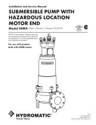
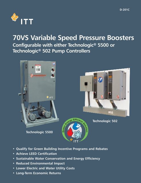
D-201C<strong>70VS</strong> <strong>Variable</strong> <strong>Speed</strong> <strong>Pressure</strong> <strong>Boosters</strong>Configurable with either Technologic ® 5500 orTechnologic ® 502 Pump ControllersTechnologic 502Technologic 5500• Qualify for Green Building Incentive Programs and Rebates• Achieve LEED Certification• Sustainable Water Conservation and Energy Efficiency• Reduced Environmental Impact• Lower Electric and Water Utility Costs• Long-Term Economic Returns
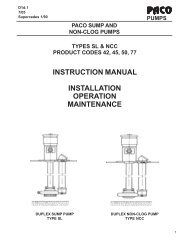
<strong>Variable</strong> <strong>Speed</strong> vs. Constant <strong>Speed</strong><strong>Pressure</strong> Boosting: How To Choose?How <strong>Variable</strong> <strong>Speed</strong>Pumping Pays offA pump is predictable inthe way it reacts to systemdemand. As the demandfluctuates, the pump ridesback and forth on its curve.A drop in demand causesthe pump to ride back onits curve and, consequently,generate more pressure. Ina pressure booster system,this additional pressure isabsorbed by the pressurereducing valve. The netresult is a waste of energy.<strong>Variable</strong> speed pumpingallows us to preciselymatch the discharge pressureof the pump to theactual system requirement.This significantly reducesthe amount of pressureabsorbed by the PRV. Insome cases, the PRV caneven be eliminated.In Figure B, the system isdesigned to provide 55PSIG at the dischargeheader. The red and bluediagonal lines representthe excess pressure generatedby the constant speedpumps. This is the pressurethat must be absorbedby the PRV's. We can alsorefer to this area as the“<strong>Variable</strong> <strong>Speed</strong> Zone”.The area represents theenergy saved by operatingat reduced speeds. Byvarying the speed of thepump(s), we can operateat any point along thebottom edge of this area.That allows us to generateonly as much pressure asthe system requires. Sinceenergy consumption of acentrifugal pump variesas the cube of speed, wecan reduce our powerconsumption by 27% bymerely reducing pumpspeed to 90%. Most variablespeed boosters arecapable of meetingdemand at significantlyless than 90% speed soyour actual savings maybe even greater.Contact your local B&GRepresentative if you'reready to enter the“VARIABLE SPEED ZONE”.COST OF ELECTRICITYA building’s domestic water usage varies during the course of a day. This graph depicts atypical commercial building load profile during the course of a day with constant suctionpressure.TYPICAL PAYBACK IN YEARSINDIVIDUAL PUMP HORSEPOWER5HP 7.5HP 10HP 15HP 20HP 25HP$.02/kWh 11.8 11.5 11.2 7.9 6.8 6.2$.04/kWh 5.9 5.8 5.6 3.9 3.4 3.1$.06/kWh 3.9 3.8 3.7 2.6 2.3 2.1$.08/kWh 3.0 2.9 2.8 2.0 1.7 1.6$.10/kWh 2.4 2.3 2.2 1.6 1.4 1.2$.12/kWh 2.0 1.9 1.9 1.3 1.1 1.0$.14/kWh 1.7 1.6 1.6 1.1 1.0 0.9$.16/kWh 1.5 1.4 1.4 1.0 0.9 0.8$.18/kWh 1.3 1.3 1.2 0.9 08 0.7$.20/kWh 1.2 1.2 1.1 0.8 0.7 0.6$.22/kWh 1.1 1.0 1.0 0.7 0.6 0.6For an in-depth analysis of domestic water pressure booster systems,refer to ITT Fluid Handling's TEH-1096 Design Manual.Primary factors inpayback analysis arethe cost of electricity,voltage available andthe load profile. Thechart to the leftdepicts the averagepayback for variouselectricity costs. Thepayback is basedon duplex pressureboosters for abuilding with aload profile shownin Figure A.
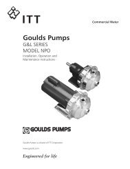
<strong>70VS</strong> PRESSURE BOOSTER SYSTEMS<strong>70VS</strong> packages are designed to provide low initial cost and the outstanding reliability you'vecome to expect from ITT Bell & Gossett. All are designed for simple installation requiring onlysuction & discharge piping connections and a single input power connection. Realizing thespace constraints of the modern equipment room, we've designed the <strong>70VS</strong> Series to occupya minimal amount of floor space. Standard features on all <strong>70VS</strong> units include:• Technologic (Pump Control Panel)• Pump isolation valves• Choice of PRV or check valve on pump discharge • Thermal relief system• UL listed• No-Flow shutdown• Low suction pressure cut out• High system pressure alarmWith a choice of three configurations and capacities from 40 GPM all the way up to 2000 GPMor more, the <strong>70VS</strong> has the flexibility to meet the requirements of most pressure booster systems.<strong>70VS</strong> SimplexThe Simplex is designed to provide the energysavings of variable speed pressure boostingat a cost that makes it an attractive choicefor small facilities. Don't let its small sizefool you—the <strong>70VS</strong> Simplex is packed withfeatures commonly found only on largemulti-pump systems. With B&G's 1510 endsuction pump and our rugged Technologiccontroller, the <strong>70VS</strong> Simplex is ideal for manypressure booster applications. For lightcommercial applications, the Mini<strong>Speed</strong>with 3530 pumps and our Technologic 502controller provides a reliable yet economicalsolution.<strong>70VS</strong>The <strong>70VS</strong> provides the added flexibility ofup to four pumps and AFDs. This gives theEngineer the capability of sizing each pumpfor a 33% of total capacity or each pumpfor 50% of total capacity. Three 50% pumpsallows you to have a redundant pump anddrive combo so you can still meet yourmaximum demand even when one pumpis down for maintenance. The <strong>70VS</strong> isavailable with Type L copper through6" and 304 stainless steel headers in sizesup to 10 inches.
<strong>70VS</strong> <strong>Variable</strong> <strong>Speed</strong> <strong>Pressure</strong> <strong>Boosters</strong>•Custom-engineered pumping systems•Serial Communications via most popular protocols•Control logic developed exclusively for pumping applications<strong>70VS</strong> <strong>Variable</strong> <strong>Speed</strong> Case StudyThe Wastewater Treatment Plant in Galesburg, IL chose the ITT treatment system as an economical way to reduce TotalSuspended Solids (TSS) concentrations, especially during high flow conditions when solids could wash out from the processes. Thewastewater treatment plant in Illinois utilizing a tertiary treatment package from ITT is reporting effluent concentrations of lessthan 5 mg/l.The Galesburg plant itself has an average design flow of 11 million gallons daily (MGD), and peak design flow of 28 MGD. The ITTpackage installed at this facility includes a DrumFilter and control system from Water & Wastewater (WWW); Flygt submersible liftstation pumps; and a triplex <strong>70VS</strong> booster pump system with a Technologic controller and variable frequency drives (VFDs) fromITT’s Residential and Commercial Water (R&CW) division.During normal filtration, no energy whatsoever is consumed by the system. Effluent flow is polished by the DrumFilters afterleaving the final clarifiers with 17-micron filtering screen.The Flygt variable speed submersible lift station pumps sequence on and off to match effluent flow feeding the DrumFilter system.Only when a backwash cycle is initiated does the DrumFilter system use energy. The filtering process is not interrupted duringthe backwash cycle, which is when the <strong>70VS</strong> system starts the lead pump by detecting a drop in the backwash line pressure.The system has the ability to sequence additionalpumps as required to meet system demand andmaintain the design pressure required to spray awaythe solids. The system in Galesburg was setup sothat the third pump in the sequence was designatedas a standby pump. The Technologic’s automaticalternation of the lead pump balances the wear oneach pump. In addition,the <strong>70VS</strong> provides remote run and alarm statusindication to the WWW monitoring and controlsystem to ensure total system integration of theITT products.The <strong>70VS</strong> system with Technologic controlsintegrates seamlessly with the DrumFilter to providean energy saving tertiary filtration solution. Benefitsof the <strong>70VS</strong> system include, 1) energy savings bymost efficiently meeting system demand,2) avoidance of motor damaging and energywasting in-rush currents with the soft start capabilityof the VFDs, 3) precise pressure control with asingle system setpoint, and 4) reliable B&G pumpprotection algorithms.A B&G Booster Package provides pressurized water during the DrumFilterBackwash sequence.© Copyright © 2009 ITT CorporationPrinted in U.S.A. 6-09THE ITT ENGINEERED BLOCKS SYMBOL ANDENGINEERED FOR LIFE ARE REGISTEREDTRADEMARKS OF ITT MANUFACTURINGENTERPRISES, INC.ITT8200 N. Austin AvenueMorton Grove, IL 60053Phone: (847) 966-3700Fax: (847) 966-9052www.bellgossett.com