NASA Motor Control Circuit (1MB PDF)
NASA Motor Control Circuit (1MB PDF)
NASA Motor Control Circuit (1MB PDF)
Create successful ePaper yourself
Turn your PDF publications into a flip-book with our unique Google optimized e-Paper software.
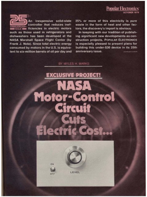
Popular Electron lcs* -n inexpensive solid-state 2S0I0 or mom of this electricity is pure, ,controller that reduces inef- waste in the form of heat and other fac- 1nI SsuE ficiencies in electric motors tors, the discovery's import is obvious.such as those used in refrigerators and In keeping with our tradition of publish-Idishwashers has been developed at the ing significant new developments as con-<strong>NASA</strong> Marshall Space Flight Center (by struction projects, POPULAR ELECTRONICS
The <strong>NASA</strong>-developed controller ismeant to work with ac induction motors,probably the type most widely used today.They characteristically run at anearly constant speed that's fixed bypower-line frequency and independentof load and supply voltage. When heavilyloaded, the motor draws line currentthat is nearly in phase with the appliedvoltage, keeping its power factor (cosineof the angle between current and voltage)high and developing a large torque.Under light load conditions, the motordevelops less torque by allowing morelag between the voltage and current.This reduces the power factor whileleaving the current essentially the samein magnitude.Though the low power factor meansthat conversion of electricity to mechanicalpower is small, the large currentcauses considerable I2R losses (heat) inthe supply lines and motor windings.This is what reduces efficiency. To minimizethis waste, Nola's device monitorsthe motor's power factor and, when itdetects light load conditions, it reducesthe supply voltage. This increases "slip"in the motor, which causes a speed reductionof 2% or less so that the motoracts as if it were heavily loaded.The current, now more nearly inphase with the voltage, therefore doesas much useful work as before, but itand the voltage are smaller, resulting ina net saving of electric power.Power Savings. The device was testedat Marshall Center on over 40 typesof motors. Power savings ranged to60%. depending on the loading. Up to40-50% power reductions are claimedfor motors running lightly or intermittentlyloaded.The savings derived by using the controllerwith motors driving relatively constantloads (refrigeration systems andpumps, for example) are smaller, sincethe device can then do little more thanreduce the 8-10°/0 safety factor allowedfor low-voltage conditions. On the otherhand, since such motors typically havelong duty cycles, significant economiesmay be realized over a period of time.Figure 1 was constructed from dataaveraged from tests made on a 5'3-hpsplit-phase motor, and %- and X-hp capacitor-startmotors. The top curveshows the typical power required for variousloads when no control system isused. The lower curve shows the powerconsumed when the power-factor controlleris used. The controller reducedthe no-load power drain by a factor of5 or 6 and increased the power factorfrom 0.2 to 0.8. In all three motors, thespeed reduction resulting from lowervoltage was less than 2%.<strong>Circuit</strong> Operation. The circuit shownin Fig. 2, which is a simplified version ofthe original invention, operates in exactlythe same manner. Also shown in Fig.2, facing the diagram are waveformsfor the corresponding letter-in-a-circlepoints on the schematic.Typically, current may lag the voltageby 80" in an unloaded motor and only30" when loaded. The controller continuouslymonitors phase angle betweenvoltage and current, producing a voltageproportional to that phase angle. Thisvoltage is summed with a preset referencevoltage that corresponds to a desiredphase angle. The difference betweenthe two produces an error signalthat biases a ramp voltage synchronizedto the 60-Hz line voltage.The intersection of the ramp and theerror voltages is detected by a squaringamplifier whose output provides propertiming for controlling a triac in series withthe motor. The triac is triggered at apoint during the cycle, and the circuitswitches to "off" as the line current goesthrough zero. Triggering the triac earlierin each half cycle raises the averagevoltage to the motor and vice versa.(Continued on page 42)Fig. 1. These curves arethe results of tests madeby <strong>NASA</strong> on a %?-hpsplit-phase and %-and 94-hpcapacitor-start motors.Note that the power-factorcontroller reduced theno-load power demandby a factor of 6. <strong>Motor</strong>slowdown was less than 2%.0 2 5 50 75 I 00"/o OF FULL LOAD (TORQUE)40 POPULAR ELECTRONICS
TIPRI AC(H0T)I IThe triac's control signal is created bysensing the voltage (A) developed at thetop end of transformer TI-which alsoserves as the power source for the conventionaldc supply. (Note how the secondaryof TI is phased with the primaryac power.) The voltage is applied viaR11 to the input of op-amp IC1 A. Sincethis op amp is operating at full gain, theoutput is a square wave at power-linefrequency. This IC has two outputs (B).One, via C8 and C9, drives the rampgenerator, which consists of Q5, Q2,and associated components. CapacitorC10 charges through R15 to form theramp. The positive-going step from IC1Aturns on Q2, thus rapidly dischargingC10 to complete the ramp function. Thenegative-going step from /CIA turns onQ5, which, in turn, causes Q2 to saturate,thus discharging C1O.Since lClA is triggered at power-linerate, the ramp generated across ClO issynced to the power line, with eachramp occupying a half power-line cycle.The other output of lClA is coupledthrough R23 to diode gate D9.A voltage proportional to the currentthrough the motor (E) develops acrosssensing resistor R1. This voltage ispassed to IClB, whose squared-off output(F) is passed through R24 to diodeD9, where it combines with the output oflClA to make waveform (G). Thesummed voltage at the cathode of D9 isdifferentiated and fed to integrator IClA,along with a dc control level determinedby LEVEL potentiometer R30. This controlis used to set the motor's optimumphase angle. Time constant network C3and R26 provide a delay to let the motordevelop maximum torque when firstturned on. Capacitor C2 provides thehigh-frequency roll-off necessary forsystem stability.Since suddenly applied loads maycause the motor to stall if the systemreacts too slowly, the circuit containssome components to prevent this fromhappening. These parts, which alter theintegrator's time constant, are shownwith an asterisk in Fig. 2 (132. R3, R4,R5, R6, Dl, 02, and Cl). If you do notneed this capability, eliminate thesecomponents and tie the positive end of-R3-RIB -TI PRI- AC (LOW)Fig. 3. Actual-size etchingand drilling guide for aprinted-circuit board forthe controller is shown above.Component layout is at top.Note that there are sevraldifferent options regardingcomponents and construction,as outlined in text and Parts List.POPULAR ELECTRONICS
C3 to the +9-volt line by replacing R6with a jumper. The lClC output signal iscoupled through R18 to the Q3 input, inparallel with the ramp from C10.Triac controller Q3-Q4 is normallybiased off by R17. When the compositesignal (ramp plus pulse) arrives at thebase of Q3, this transistor will turn onwhen the peak of the composite signalovercomes the bias. Since the ramp levelis fixed, the pulse from ICIC, controlledby R30, determines when the Q3-Q4 combination turns on. When turn-onoccurs, the waveform shown at (D) triggersthe triac, thus applying voltage tothe motor.Construction. The circuit can bemost easily assembled on a pc boardusing the foil pattern and componentlayout shown in Fig. 3. A bridge rectifiercan be used in place of the four rectifierdiodes (03-06). If a 24-volt transformeris employed, increase the value of R7 to150 ohms. Resistor R1 can be fabricatedfrom a 9" length of #22, or a 6" lengthof #24 solid copper wire that's wound onan insulated support dowel.At this time, you make the decisionabout the aforementioned possibility ofsudden or clutched-in loads that wouldrequire using the asterisked components.Furthermore, if this device is to beused with motors requiring in excess of300 watts, to prevent damage to thetriac or pc board, remove the triac, R1and the ac input from the board. mountinga terminal strip in their place. Mountthe triac with R1 to the chassis or optionalheat sink (suitably isolated) and wirethem into the circuit board, using the terminalstrip. Make sure that the "low"side of the ac line is used as the circuitcommon, and use polarized plugs for allac-power connections. Do not use themetal chassis as the common ground!Failure to observe these precautionsmay cause a serious shock hazard.Mount the pc board and transformer ina chassis, securing the board on insulatedspacers so that no part of the ac linemakes contact with the chassis. If desired,LEVEL potentiometer R30 can beremoved from the pc board and a conventionalrotary potentiometer of thesame value can be mounted on thechassis. The motor can be plugged intoan optional socket mounted on the chassis(wired to the motor-connector padson the pc board), or use a suitablelength of heavy-duty ac line cord havinga socket at one end. Do not forget to useac line cord having sufficient currentcarryingcapacity to handle the load.OCTOBER 1979Photograph of the author's prototype which was built on perf board,though a printed circuit board is recommended. The binding posts.and switch on the rear were used for testing during design.Since many of the systems to whichthe controller can be usefully appliedhave motors fed from 220-volt ac mains,you may wish to adapt the circuit to workat that voltage. This can be done by exchangingT1 for a similar transformerwith twice as many primary turns andsubstituting a higher voltage triac (400PIV minimum). Both "hot" legs of the220-volt line should be isolated from thechassis, while the center tap should beconnected to the ground circuit. An appropriateline plug and receptacle canbe used, or the controller can be hardwiredto the load.Use. Plug the power-factor controllerinto an ac outlet and connect the motorto be controlled. Turn both on. With themotor operating, slowly adjust LEVELcontrol R30 until a slight drop in speedor mechanical power is noticed. Vibration,too, will probably diminish. Slightlyback off on R30 until you feel the pointwhere the speed barely drops off. Thisshould be the optimum setting of thecontroller. It will probably be necessaryto readjust R30 for each different motoryou wish to control.As noted earlier, the savings effectedby using the power factor controller (andthe length of time required for the deviceto pay for itself) depend on the way inwhich a particular motor is loaded andfor what proportion of the time it is inuse. Clearly, intermittently used appliancessuch as power tools are poor candidates.In most households, refrigerators,air conditioners, ventilating fans.swimming-pool pumps, and other machinesthat run for extended periods willlet the power factor controller pay for itselfmore quickly than smaller and/or intermittentlyused appliances. Savingswill depend on your electric rates, too. InNew York City, where one kilowatt-hourcosts 11.5 cents in the summer and 9.52cents in the winter, the controller, usedon a 16-cu-ft frostfree freezer, might wellpay for itself in about two years. 043


