
Create successful ePaper yourself
Turn your PDF publications into a flip-book with our unique Google optimized e-Paper software.
EngineeringDependableProtectionFor AnElectricalDistributionSystemBulletin <strong>EDP</strong>-3(2004-3)Part 3ComponentProtection forElectricalSystems<strong>Bussmann</strong>
Jeder Qualitätsmanager sollte daher über die rechtliche Bedeutung des QualitätsmanagementsystemsBescheid wissen. Das ist das Ziel dieses Buches.Dabei wird das Wissen um die bekannten QM-Systeme nur am Rande behandelt.- Zunächst werden Schnittstellen zwischen Qualitätsmanagement und Rechtaufgezeigt. Es wird deutlich werden, daß die Rechtsordnung beziehungsweisedie Rechtsprechung deutscher Obergerichte zur Erreichung notwendigerQualität von Produkten hohe Forderungen an die Organisation derUnternehmen stellen.- Danach werden normierte Qualitätsmanagementsysteme vorgestellt, diedie Grundvoraussetzungen für ein funktionierendes und gefahrenadäquatesOrganisationsmodell der Produktion beschreiben.- Ganz konkret wird an Beispielen aus der Praxis der Zusammenhang zwischenQualität und Recht dargelegt. Auf der Grundlage einiger Entscheidungendeutscher Obergerichte werden Forderungen an Organisationssystemezur Produktion definiert und Umsetzungsmöglichkeiten durch QM-Systeme aufgezeigt.- Abschließend werden allgemeine, übergreifende Probleme an der SchnittstelleQualität und Recht aufgezeigt (TQM, Lean Management etc.).-2-
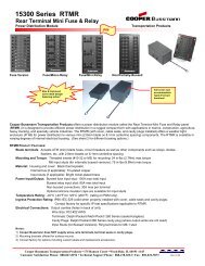
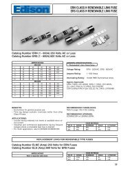
Protecting System ComponentsA. Wire and CableAllowable Short-Circuit Currents for Insulated Copper Conductors*10080SHORT CIRCUIT CURRENT - THOUSANDS OF AMPERES6050403020108654321.8.6.5.4.31 CYCLE – 0.0167 SECOND2 CYCLES – 0.0333 SECOND4 CYCLES – 0.0667 SECOND8 CYCLES – 0.1333 SECOND16 CYCLES – 0.2667 SECOND30 CYCLES – 0.5000 SECOND60 CYCLES – 1.0000 SECOND100 CYCLES – 1.6667 SECONDCONDUCTOR: COPPERINSULATION: CROSSLINKED POLYETHYLENE ÐYLENE PROPYLENE RUBBERCURVES BASED ON FORMULA:⎡ I ⎤ 2 t = .0297 log ⎡ T 2 + 234 ⎤⎣A ⎦⎣T 1 + 234 ⎦WHERE:I = SHORT-CIRCUIT CURRENT - AMPERESA = CONDUCTOR AREA - CIRCULAR MILSt = TIME OF SHORT-CIRCUIT - SECONDST 1 = MAXIMUM OPERATING TEMPERATURE - 90°CT 2 = MAXIMUM SHORT-CIRCUIT TEMPERATURE -250°C.2.110 8 6 4 2 1 1/0 2/0 3/0 4/0 AWGCONDUCTOR SIZE 250 MCM 500 1000Figure 8. Short-Circuit Current Withstand Chart for Copper Cables with Crosslinked Polyethylene & Ethylene Propylene Rubber Insulation*Copyright 1969 (reaffirmed March, 1992) by the Insulated Cable Engineers Association (ICEA). Permission has been given by ICEA to reprint this chart.10
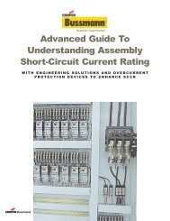
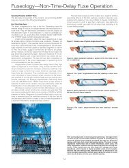
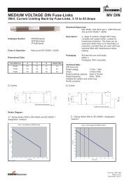
Protecting System ComponentsA. Wire and CableAllowable Short-Circuit Currents for Insulated Aluminum Conductors*1008060504030SHORT CIRCUIT CURRENT - THOUSANDS OF AMPERES20108654321.8.6.5.4.3.21 CYCLE – 0.0167 SECOND2 CYCLES – 0.0333 SECOND4 CYCLES – 0.0667 SECOND8 CYCLES – 0.1333 SECOND16 CYCLES – 0.2667 SECOND30 CYCLES – 0.5000 SECOND60 CYCLES – 1.0000 SECOND100 CYCLES – 1.6667 SECONDCONDUCTOR: ALUMINUMINSULATION: PAPER, RUBBER, VARNISHEDCLOTHCURVES BASED ON FORMULA:⎡ I ⎤ 2 t = .0125 log ⎡ T 2 + 228 ⎤⎣A ⎦⎣T 1 + 228 ⎦WHERE:I = SHORT-CIRCUIT CURRENT - AMPERESA = CONDUCTOR AREA - CIRCULAR MILSt = TIME OF SHORT-CIRCUIT - SECONDST 1 = MAXIMUM OPERATING TEMPERATURE -75°CT 2 = MAXIMUM SHORT-CIRCUIT TEMPERATURE -200°C.110 8 6 4 2 1 1/0 2/0 3/0 4/0 AWGCONDUCTOR SIZE 250 MCM 500 1000Figure 9. Short-Circuit Current Withstand Chart for Aluminum Cables with Paper, Rubber, or Varnished Cloth Insulation*Copyright 1969 (reaffirmed March, 1992) by the Insulated Cable Engineers Association (ICEA). Permission has been given by ICEA to reprint this chart.11
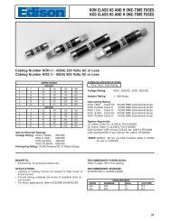
Protecting System ComponentsA. Wire and CableAllowable Short-Circuit Currents for Insulated Aluminum Conductors*1008060504030SHORT CIRCUIT CURRENT - THOUSANDS OF AMPERES20108654321.8.6.5.4.3.21 CYCLE – 0.0167 SECOND2 CYCLES – 0.0333 SECOND4 CYCLES – 0.0667 SECOND8 CYCLES – 0.1333 SECOND16 CYCLES – 0.2667 SECOND30 CYCLES – 0.5000 SECOND60 CYCLES – 1.0000 SECOND100 CYCLES – 1.6667 SECONDCONDUCTOR: ALUMINUMINSULATION:THERMOPLASTICCURVES BASED ON FORMULA:⎡ I ⎤ 2 t = .0125 log ⎡ T 2 + 228 ⎤⎣A ⎦⎣T 1 + 228 ⎦WHERE:I = SHORT-CIRCUIT CURRENT - AMPERESA = CONDUCTOR AREA - CIRCULAR MILSt = TIME OF SHORT-CIRCUIT - SECONDST 1 = MAXIMUM OPERATING TEMPERATURE -75°CT 2 = MAXIMUM SHORT-CIRCUIT TEMPERATURE -150°C.110 8 6 4 2 1 1/0 2/0 3/0 4/0 AWGCONDUCTOR SIZE 250 MCM 500 1000Figure 10. Short-Circuit Current Withstand Chart for Aluminum Cable with Thermoplastic Insulation*Copyright 1969 (reaffirmed March, 1992) by the Insulated Cable Engineers Association (ICEA). Permission has been given by ICEA to reprint this chart.12
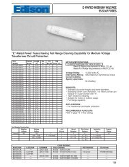
Protecting System ComponentsA. Wire and CableAllowable Short-Circuit Currents for Insulated Aluminum Conductors*1008060504030SHORT CIRCUIT CURRENT - THOUSANDS OF AMPERES20108654321.8.6.5.4.3.21 CYCLE – 0.0167 SECOND2 CYCLES – 0.0333 SECOND4 CYCLES – 0.0667 SECOND8 CYCLES – 0.1333 SECOND16 CYCLES – 0.2667 SECOND30 CYCLES – 0.5000 SECOND60 CYCLES – 1.0000 SECOND100 CYCLES – 1.6667 SECONDCONDUCTOR: ALUMINUMINSULATION: CROSSLINKED POLYETHYLENE ÐYLENE PROPYLENE RUBBERCURVES BASED ON FORMULA:⎡ I ⎤ 2 t = .0125 log ⎡ T 2 + 228 ⎤⎣A ⎦⎣T 1 + 228 ⎦WHERE:I = SHORT-CIRCUIT CURRENT - AMPERESA = CONDUCTOR AREA - CIRCULAR MILSt = TIME OF SHORT-CIRCUIT - SECONDST 1 = MAXIMUM OPERATING TEMPERATURE - 90°CT 2 = MAXIMUM SHORT-CIRCUIT TEMPERATURE -250°C.110 8 6 4 2 1 1/0 2/0 3/0 4/0 AWGCONDUCTOR SIZE 250 MCM 500 1000Figure 11. Short-Circuit Current Withstand Chart for Aluminum Cables with Crosslinked Polyethylene & Ethylene Propylene RubberInsulation*Copyright 1969 (reaffirmed March, 1992) by the Insulated Cable Engineers Association (ICEA). Permission has been given by ICEA to reprint this chart.13
Protecting System ComponentsA. Wire and CableProtecting Equipment Grounding ConductorsSafety issues arise when the analysis of equipmentgrounding conductors is discussed. Table 250-95 of theNEC offers minimum sizing for equipment groundingconductors.The problem of protecting equipment groundingconductors was recognized more than 30 years ago whenEustace Soares, wrote his famous grounding book“Grounding Electrical Distribution Systems for Safety". In hisbook he states that the “validity” rating corresponds to theamount of energy required to cause the copper to becomeloose under a lug after the conductor has had a chance tocool back down. This validity rating is based upon raisingthe copper temperature from 75°C to 250°C.In addition to this and the ICEA charts, a third methodpromoted by Onderdonk allows the calculation of theenergy necessary to cause the conductor to melt (75°C to1,083°C).Table 2 offers a summary of these values associatedwith various size copper conductors.It becomes obvious that the word “Minimum” in theheading of table 250-95 means just that - the values in thetable are a minimum - they may have to be increased dueto the available short-circuit current and the current-limiting,or non-current-limiting ability of the overcurrent protectivedevice.Good engineering practice requires the calculation ofthe available short-circuit currents (3-phase and phase-togroundvalues) wherever equipment grounding conductorsare used. Overcurrent protective device (fuse or circuitbreaker) manufacturers’ literature must be consulted. Letthruenergies for these devices should be compared withthe short-circuit ratings of the equipment groundingconductors. Wherever let-thru energies exceed the“minimum” equipment grounding conductor withstandratings, the equipment grounding conductor size must beincreased until the withstand ratings are not exceeded.Table 2. Comparison of Equipment Grounding Conductor Short-Circuit Withstand Ratings5 Sec. Rating (Amps) I 2 t Rating x10 6 (Ampere Squared Seconds)ICEA Soares Onderdonk ICEA Soares OnderdonkP32-382 1 Amp/30 cm Melting P32-382 1 Amp/30 cm MeltingInsulation Validity Point Insulation Validity PointConductor Damage DamageSize 150°C 250°C 1,083°C 150°C 250°C 1,083°C14 97 137 253 .047 .094 .32012 155 218 401 .120 .238 .80410 246 346 638 .303 .599 2.038 391 550 1,015 .764 1.51 5.156 621 875 1,613 1.93 3.83 13.04 988 1,391 2,565 4.88 9.67 32.93 1,246 1,754 3,234 7.76 15.4 52.32 1,571 2,212 4,078 12.3 24.5 83.11 1,981 2,790 5,144 19.6 38.9 132.01/0 2,500 3,520 6,490 31.2 61.9 210.02/0 3,150 4,437 8,180 49.6 98.4 331.03/0 3,972 5,593 10,313 78.9 156.0 532.04/0 5,009 7,053 13,005 125.0 248.0 845.0250 5,918 8,333 15,365 175.0 347.0 1,180.0300 7,101 10,000 18,438 252.0 500.0 1,700.0350 8,285 11,667 21,511 343.0 680.0 2,314.0400 9,468 13,333 24,584 448.0 889.0 3,022.0500 11,835 16,667 30,730 700.0 1,389.0 4,721.0600 14,202 20,000 36,876 1,008.0 2,000.0 6,799.0700 16,569 23,333 43,022 1,372.0 2,722.0 9,254.0750 17,753 25,000 46,095 1,576.0 3,125.0 10,623.0800 18,936 26,667 49,168 1,793.0 3,556.0 12,087.0900 21,303 30,000 55,314 2,269.0 4,500.0 15,298.01,000 23,670 33,333 61,460 2,801.0 5,555.0 18,867.014
Protecting System ComponentsB. Bus Short-Circuit Rating and Bracing RequirementsBus Short-Circuit Rating Requirements When Protected byCurrent-Limiting FusesNEMA Standards require that busways have asymmetrical short-circuit withstand rating at least as greatas the average available symmetrical short-circuit current.*Since the short-circuit ratings of busways areestablished on the basis of minimum three-cycle durationtests, these ratings will not apply unless the protectivedevice used will remove the fault within three cycles orless.*BUSWAYS MAY BE USED ON CIRCUITS HAVINGAVAILABLE SHORT-CIRCUIT CURRENTS GREATER THANTHE BUSWAY RATING WHEN PROPERLY COORDINATED,AND RATED WITH CURRENT-LIMITING DEVICES.*If a busway has been listed or labeled for a maximumshort-circuit current with a specific overcurrent device, itcannot be used where greater fault currents are availablewithout violating the listing or labeling. If a busway hasbeen listed or labeled for a maximum short-circuit currentwithout a specific overcurrent device (i.e., for three cycles),current-limiting fuses can be used to reduce the availableshort-circuit current to within the withstand rating of thebusway.Refer to Figure 12 for an analysis of the short-circuitrating requirements for the 800 ampere plug-in bus.65,000 AmpsRMS SymAvailableKRP-C800SP Amp LOW-PEAK ®Time-Delay Fuses800 Amp SwitchBracing Required?Short-Circuit800 Amp Plug-in BusFigure 12. Determining the Short-Circuit Ratings of BuswayThe 800 ampere plug-in bus in Figure 12 could besubjected to 65,000 amperes at its line side; however, theKRP-C800SP ampere LOW-PEAK ® time-delay fuse wouldlimit this available current. Upon checking the Data Section,page 25, when protected by KRP-C800SP ampere LOW-PEAK time-delay fuses, the 800 ampere bus need only bebraced for 19,000 amperes RMS symmetrical. This wouldallow a standard 22,000 ampere RMS symmetrical (3-cycle) rated bus to be specified, whereas, if a non-currentlimitingtype protective device were specified, the bracingrequirements would have been 65,000 amperes for threecycles.CURRENT-LIMITING FUSES GENERALLY REDUCEBUS BRACING REQUIREMENTS TO ALLOW A STANDARDSHORT-CIRCUIT RATED BUSWAY TO BE SPECIFIED.When applying air frame circuit breakers with shorttime-delay (STD), the engineer must specify additionalshort-circuit bracing based on the STD time setting. Forexample, an 800 ampere air frame circuit breaker mayhave an intentional 18 cycle STD to selectively coordinatewith downstream breakers. It is imperative that the 800ampere busway also be braced for this 18 cycles to avoiddamage or destruction.The busway short-circuit short time rating has amechanical limit. Exceeding this limit invites mechanicaldamage due to the high magnetic forces associated withthe peak current of the fault. The mechanical limit typicallyapplies for high faults near and below the busway shortcircuitrating. Allowable durations of short-circuit current,longer than the 3-cycles at 60 Hz (0.05 seconds) requiredat the maximum short-circuit rating, are obtained from aconstant I 2 t “mechanical damage limit” curve.Typically, for currents below one-half of the short-circuitcurrent rating, where mechanical stresses are reduced toone-quarter of those at the maximum rating, themechanical capabilities become less important than thethermal capability. The lower limit duration at one-half thebusway rating is determined by the busway thermal (I 2 t)capabilities.The following examples compare busway short-circuitovercurrent protection by low voltage circuit breakers andcurrent-limiting fuses. This study looks at the developmentof the busway mechanical withstand curves and the timecurrentcurves of the breakers and fuses.In this example, the 800 ampere plug-in busway has a65 kA short-circuit rating.A plot of the busway mechanical limit characteristic onlog-log paper (Figure 13) passes through the short-circuitrating at (65 kA, 0.05 seconds) and is a constant I 2 t downto 32.5 kA (one-half the short-circuit rating of 65 kA).Assume the available short-circuit current at thebusways is equal to the 65 kA rating. The overcurrentdevices are assumed to have the proper interruptingcapacity.In order to coordinate selectively with circuit breakersthat are instantaneously tripped, the power circuit breakerprotecting the busway does not have an instantaneous trip.There is a problem with the protection of this busway.The short time-delay needed to achieve coordinationresults in a lack of protection of the 800 ampere busway. Ashort-circuit on this busway can result in damage. As notedon the curve, a 65,000 ampere fault will intersect themechanical damage curve before the breaker trips.This busway would have to be braced to withstand65,000 amperes of short-circuit current for a minimum of 12cycles.A plot of the same system utilizing LOW-PEAK Class Land Class RK1 fuses is given in Figure 14. Currentlimitation by the KRP-C800SP will offer short-circuitprotection for the busway, as it lets through 19,000amperes.Note: The Busway is protected by the fast speed ofresponse in the high short-circuit region. Protection isachieved, as is selective coordination, with the downstreamLPS-RK400SP fuse.* NEMA Pub. No. BU1-1988.15
Protecting System ComponentsB. Bus Short-Circuit Rating and Bracing RequirementsTable 3.NEMA (Standard Short-Circuit Ratings of Busway*)Continuous Current Short-Circuit Current RatingsRating of Busway (Symmetrical Amperes)(Amperes) Plug-In Duct Feeder Duct100 10,000 –225 14,000 –400 22,000 –600 22,000 42,000800 22,000 42,0001000 42,000 75,0001200 42,000 75,0001350 42,000 75,0001600 65,000 100,0002000 65,000 100,0002500 65,000 150,0003000 85,000 150,0004000 85,000 200,0005000 – 200,0001,0008006004003002001008060403020800A AFCB400A MCCBTable 3 pertains to feeder and plug-inbusway. For switchboard and panelboardstandard ratings refer to manufacturer.U.L. Standard 891 details short-circuitdurations for busway within switchboardsfor a minimum of three cycles, unless themain overcurrent device clears the short inless than three cycles.TIME IN SECONDS1086432800AAFCB400A CB* Reprinted with permission ofNEMA, Pub. No. BU1-1988.1.8.6.4800A Plug-inBusway.3.2.1.08.06.04.03Short TimeDelay - 6 CyclesBuswayMechanicalCapability.02.011002003004006008001,0002,0003,0004,0006,0008,00010,000CURRENT IN AMPERES20,00030,00040,00060,00080,000100,00065,000AShort-CircuitFigure 13.16
Protecting System ComponentsB. Bus Short-Circuit Rating and Bracing Requirements1,0008006004003002001008060LPS-RK400SPKRP-C800SP403020TIME IN SECONDS1086432KRP-C800SPLPS-RK400SP1.8.6.4.3.2.1.08.06.04.03BuswayMechanicalCapability.02.01100Figure 14.2003004006008001,0002,0003,0004,0006,0008,000CURRENT IN AMPERES10,00020,00030,00040,00060,00080,000100,00065,000AShort-Circuit17
Protecting System ComponentsC. Low Voltage Motor ControllersThe diagram in Figure 15 shows a Size 2, combinationmotor controller supplying a 460 volt, 3Ø, 20HP motor. Theshort-circuit withstand of this and other motor controllersare established so that they may be properly protectedfrom short-circuit damage.40,000 RMSSymmetricalAvailable3Ø, 460VLow-Peak ®Dual ElementTime Delay FuseFigure 15. Short-Circuit Protection of Motor ControllerThere are several independent organizations engagedin regular testing of motor controllers under short-circuitconditions. One of these, Underwriter’s Laboratories, testscontrollers rated one horsepower or less and 300 volts orless with 1000 amperes short-circuit current available to thecontroller test circuit. Controllers rated 50HP or less aretested with 5000 amperes available and controllers ratedabove 50HP to 200HP are tested with 10,000 amperesavailable. See Table 4 for these values.*Table 4.Motor ControllerTest Short CircuitHP RatingCurrent Available1HP or less and 300V or less 1,000A50HP or less 5,000AGreater than 50HP to 200HP 10,000A201HP to 400HP 18,000A401HP to 600HP 30,000A601HP to 900HP 42,000A901HP to 1600HP 85,000AIt should be noted that these are basic short-circuitrequirements. Higher, combination ratings are attainable iftested to an applicable standard. However, damage isusually allowed.Type 1 vs. Type 2 ProtectionUL has developed a short-circuit test proceduredesigned to verify that motor controllers will not be a safetyhazard and will not cause a fire.Compliance to the standard allows deformation of theenclosure, but the door must not be blown open and it mustbe possible to open the door after the test. In the standardshort-circuit tests, the contacts must not disintegrate, butwelding of the contacts is considered acceptable. Whentesting with fuses, damage to the overload relay is notallowed, and it must perform in accordance with thecalibration requirements. Tests with circuit breakers allowthe overload relay to be damaged with burnout of thecurrent element completely acceptable.For short-circuit ratings in excess of the standardlevels listed in UL508, the damage allowed is even moresevere. Welding or complete disintegration of contacts isacceptable and complete burnout of the overload relay isallowed. Therefore, a user cannot be certain that the motorstarter will not be damaged just because it has been U.L.Listed for use with a specific branch circuit protectivedevice. U.L. tests are for safety, but do allow a significantamount of damage as long as it is contained within theenclosure.MTypical Size 2 Controller20HP3Ø, 460V27 F.L.A.In order to properly select a branch circuit protectivedevice that not only provides motor branch circuitprotection, but also protects the circuit components fromdamage, the designer must look beyond mere safetystandards. Coordination of the branch circuit protectivedevice and the motor starter is necessary to insure thatthere will be no damage or danger to either the starter orthe surrounding equipment. There is an IEC (InternationalElectrotechnical Commission) Standard that offersguidance in evaluating the level of damage likely to occurduring a short-circuit with various branch circuit protectivedevices. IEC Publication 947, “Low Voltage Switchgear andControl, Part 4-1: Contactors and Motor Starters",addresses the coordination between the branch circuitprotective device and the motor starter. It also provides amethod to measure the performance of these devicesshould a short-circuit occur. IEC defines two levels ofprotection (coordination) for the motor starter:Type 1. Considerable damage to the contactor andoverload relay is acceptable. Replacement of componentsor a completely new starter may be needed. There must beno discharge of parts beyond the enclosure.Type 2. No damage is allowed to either the contactoror overload relay. Light contact welding is allowed, butmust be easily separable.Where Type 2 protection is desired, the controllermanufacturer must verify that Type 2 protection can beachieved by using a specified protective device. U.S.manufacturers have recently begun having both theirNEMA and IEC motor controllers verified to meet the Type 2requirements outlined in IEC 947-4. As of this writing onlycurrent-limiting fuses have been able to provide thecurrent-limitation necessary to provide verified Type 2protection. In many cases, Class J, Class RK1, or Class CCfuses are required, because Class RK5 fuses and circuitbreakers aren’t fast enough under short-circuit conditionsto provide Type 2 protection.Section 430-52 of the National Electrical Code allowsDual Element Time-Delay fuses and other overcurrentprotective devices to be sized for branch circuit protection(short-circuit protection only). Controller manufacturersoften affix labels to the inside of the motor starter coverwhich recommend the maximum size fuse for eachoverload relay size.A paragraph in Section 430-52 states:“Where maximum branch circuit protective deviceratings are shown in the manufacturer’s overload relay tablefor use with a motor controller or are otherwise marked onthe equipment, they shall not be exceeded even if highervalues are allowed as shown above.”**This paragraph means that the branch circuitovercurrent protection for overload relays in motorcontrollers must be no greater than the maximum size asshown in the manufacturer’s overload relay table. Thesemaximum branch circuit sizes must be observed eventhough other portions of Section 430-52 allow larger sizingof branch circuit overcurrent protection.The reason for this maximum overcurrent device size isto provide short-circuit protection for the overload relaysand motor controller.**“Above”refers to other portions of Section 430-52 not shown here.* From Industrial Control Equipment, U.L. #508.18
Protecting System ComponentsD. Molded Case Circuit BreakersUntil recently, molded case circuit breakers wereprotected the same way as other electrical equipment.Quicker acting circuit breakers, as well as test circuits thatcause short-circuit test parameters to change, haverequired additional considerations in recommendedprotection procedures.As has been discussed previously, the two parametersIRMS and Ip, must be compared to the equipment withstandrating. The rule is simple: if the RMS and peak let-thru valueof the fuse are less than the equipment withstand rating,the equipment will be protected. This philosophy holds truefor various static components, such as wire and cable,busway, and motor starters. This basic protectionrequirement is mandated in NEC Section 110-10. It will alsobe true for non-current-limiting circuit breakers when theiropening time is greater than one-half cycle.In the past, as long as the fuse let-thru values wereless than the breaker’s interrupting rating, the system wasconsidered sound. THIS METHOD HAS A SOLID HISTORYOF SUCCESSFUL APPLICATIONS. However, due tochanges in circuit breaker design, the method may notalways work with today’s circuit breakers. Selecting acurrent-limiting fuse to protect a downstream molded casecircuit breaker has now become an increasingly morecomplex problem.Quicker Operating Circuit BreakersSimply put, if the total clearing energy of a quickeracting molded case circuit breaker is less than the meltingenergy of a larger upstream fuse, the molded case circuitbreaker will interrupt the full value of the system faultwithout the benefit of the fuse’s current-limiting effect. Thissituation can have catastrophic effects on the circuitbreaker as it tries to interrupt faults beyond its interruptingcapacity. Currently, there is no available engineeringmethod to predict protection of these faster breakers.Molded Case Circuit Breakers - Agency Test ProceduresSome agency standards allow a unique test set-up fortesting circuit breaker interrupting ratings. Figure 16illustrates a typical calibrated test circuit waveform for a20A, 240-volt, two-pole molded case circuit breaker, with amarked interrupting rating of 22,000 amperes RMSsymmetrical. Figure 17 also illustrates the calibrationrequired by the standard, and the maximum peak currentavailable at a 20% power factor. However, agencystandards allow for a random close during the short-circuittest, so the peak available current may be as low as 1.414times the RMS current for one- and two-pole circuitbreakers. For three-pole circuit breakers, one pole may seea peak of only 1.414 x RMS. The conservative approachwould therefore assume a 1.414 multiplier also for threepolebreakers.I p = 48,026AAmpsFigure 16S.C.P.F. = 20%S.C. Avail. = 22,000AR SX SSOURCE:Figure 17Standard interrupting rating tests will allow for amaximum 4-foot rated wire on the line side, and a 10-inchrated wire on the load side of the circuit breaker.Performing a short-circuit analysis of this test circuit resultsin the following short-circuit parameters, as seen by thecircuit breaker.Actual short-circuit RMS current = 9,900 amperes RMSsymmetricalActual short-circuit power factor = 88%Actual short-circuit peak current = 14,001 amperesA graphic analysis of this actual short-circuit follows(Figure 18).Figure 18I RMS = 22,000ATime20AR LINE X LINER CB X CB4' Rated Wire (#12 Cu)P.F. = 20%I RMS = 22,000 AmpR LOADNote: For calculations, R CB and X CB are assumed negligible.I p = 14,001AAmpsI RMS = 9,900ATimeX LOAD10" Rated Wire (#12 Cu)P.F. = 88%I RMS = 9,900 Amp19Agency standards allow for a random close duringthe short-circuit test, so the peak available current maybe as low as 1.414 times the RMS symmetrical current.Thus, the circuit breaker is actually tested to interrupt9,900 amperes at 88% power factor, not 22,000 amperes at20% power factor.
Protecting System ComponentsD. Molded Case Circuit BreakersFigure 19 shows the waveforms superimposed forcomparison. Henceforth, this RMS test value will beidentified as the circuit breaker interrupting capacity. (Don’tconfuse this with the circuit breaker marked interruptingrating.)I p = 48,026AI p = 14,001AAmpsFigure 19I RMS = 22,000AI RMS = 9,900ATimeThe following definitions should be noted:P.F. = 88%I RMS = 9,900 AmpInterrupting Rating (CB): The marked rating shownon the Circuit Breaker. It has been established by testing.*Interrupting Capacity (CB): Actual test Ip and IRMSthe circuit breaker sees during the tests for standard circuitbreaker applications.*Equally important, the short-circuit power factor isgreatly affected due to the high R values of the small, ratedwire. This results in a lower peak value that the circuitbreaker must tolerate during the first one-half cycle.* These definitions paraphrase those given in the IEEE Standard Dictionary ofElectrical and Electronic Terms, page 462, 1984 edition.Following is a partial table showing the actual Ip andI RMS values to which a circuit breaker may be tested.Table 5. 240V - 2-Pole CB Interrupting Capacities (KA)CB 10kA 14kA 18kARating I p I RMS I p I RMS I p I RMS15 7.2 5.1 8.7 6.1 9.3 6.620 8.9 6.3 11.4 8.1 12.6 8.925 10.7 7.5 14.2 10.1 16.5 11.730 10.7 7.5 14.2 10.1 16.5 11.740 11.7 8.3 16.0 11.3 19.2 13.650 11.7 8.3 16.0 11.3 19.2 13.660 12.5 8.8 17.3 12.2 21.3 15.170 13.0 9.2 18.1 12.8 22.6 16.080 13.0 9.2 18.1 12.8 22.6 16.090 13.2 9.3 18.3 12.9 23.0 16.3100 13.2 9.3 18.3 12.9 23.0 16.3After reviewing the values to which the circuit breakercan be tested (its interrupting capacity) it becomes obviousthat a circuit breaker’s interrupting rating cannot beconsidered its short-circuit withstand rating (especially forbreakers with higher interrupting ratings).“Fully Rated System”: A fully rated system is acombination of overcurrent devices that have aninterrupting rating equal to or greater than the availableshort-circuit current.“Series Rated System”: Although there is no officialdefinition, a series rated system can be described as acombination of circuit breakers or fuses and breakers thatcan be applied at available fault levels above theinterrupting rating of the load side circuit breakers, but notabove that of the main or line side device (formerly knownas a Cascaded System).<strong>Bussmann</strong>’s recommendation is to use fully ratedovercurrent devices. But, when recently produced lightingand receptacle circuit breakers are utilized at valuesbeyond their interrupting rating, the recommendedalternative is to use listed systems which utilize tested andrecognized combinations of main fuses and load sidecircuit breakers.20
Protecting System ComponentsE. Transformers1. Overload ProtectionThe National Electrical Code has developed separatesections and sizing recommendations for fuses withprimary voltages above and below 600 volts, nominal. Thefollowing three paragraphs cover the basic requirements.See NEC Sections 450-3 and 430-72 for the most commonexceptions.Section 450-3a covers transformer protection when theprimary voltage is greater than 600 volts. For lowimpedance transformers, fuse protection on the primarycan be sized as high as 300% of primary current.Secondary protection must be offered at 250% or 125% forsecondary voltages greater than 600 volts, or 600 volts orless, respectively. See Figures 20 and 21.Table 6. 450-3(a)(1) Transformers Over 600 VoltsMaximum Rating or Setting for Overcurrent DevicePrimarySecondaryOver 600 Volts Over 600 Volts 600 Voltsor BelowTransformer Circuit Circuit Circuit BreakerRated Breaker Fuse Breaker Fuse Setting orImpedance Setting Rating Setting Rating Fuse RatingNot morethan 6% 600% 300% 300% 250% 125%More than 6%and not morethan 10% 400% 300% 250% 225% 125%Figure 20Fuse at 300% ofF.L.A. of primaryZ = 6% (or less)PRI. SEC.over 600V600V or lessPRIMARY PROTECTION ONLYPRI. & SEC.600V or lessUnsupervisedLocationFuse at 125% ofF.L.A. of secondarySection 450-3b covers transformer protection when theprimary voltage is 600 volts or less. Primary fusing at 125%of primary current will not require secondary protection.Note: Secondary conductor and panelboard protection aremost often required by Articles 240 and 384 respectively.Primary and secondary protection are required whenthe primary fuse is greater than 125%. The primary fusemay be sized no larger than 250% of primary current. Thesecondary fuse should then be sized no larger than 125%of the secondary current.2. Magnetizing Inrush CurrentsPrimary fuses must be capable of handling the inrushcurrents associated with the transformer during start-up. Arule of thumb is that the fuse handle 12x full load current for0.1 seconds, and 25x full load current for 0.01 seconds.Dual-element time-delay fuses are best suited to meet thesizing criteria of Article 450 and pass these initial surgecharacteristics.Refer to <strong>Bussmann</strong> Bulletin <strong>EDP</strong> II for a discussion ofthese inrush points.3. Short-Circuit Protection - Thermal and MagneticWithstand curves for distribution transformers definehow much current a transformer can withstand, and for howlong. As with any electrical component, if these curves areexceeded the transformer may be damaged or destroyed.These curves relate to both thermal and mechanicaldamage, and are defined by different fault conditions.Typically, three curves exist for a 3-phase transformer,defined by phase-phase, phase-phase-phase, and phasegroundfault conditions.It is the designer’s goal to find a fuse time-currentcurve that falls to the left of the damage curves and to theright of the transformer inrush points.Refer to <strong>Bussmann</strong> Bulletin <strong>EDP</strong> II for a discussion ofhow to analyze these curves and protection levels.Fuse must not belarger than 125%of F.L.A. of primaryNo secondaryprotectionPRIMARY AND SECONDARY PROTECTION ONLYPRI. & SEC.600V or lessFuse no larger than250% of F.L.A.of primary whensecondary fusesare provided at 125%125% of F.L.A.of secondary(except as noted above)Figure 2121
Protecting System ComponentsF. BallastsThe National Electrical Code requires integral thermalprotection for ballasts in Section 410-73(e).Testing agencies list ballasts for general use in lightingfixtures which pass specific thermal and short-circuit tests.The ballast must incorporate a thermal protector to sensecertain over-temperature conditions and must also be ableto withstand 200 amperes of short-circuit current whentested with a 20 ampere fuse. See Figure 22 for a typicaltest for ballasts.Most systems today will deliver more than 200amperes of short-circuit current to a row of fixtures. (SeeFigure 23.) The fixtures should, therefore, be specified toincorporate individual ballast fusing within the fixture andexternal to the ballast.Fusing each fixture, as shown in Figure 23, will alsoprovide isolation of the faulted ballast and reduce costlyand dangerous blackouts. When a ballast does fail, onlythe fuse protecting that individual fixture opens - theremaining fixtures continue in normal operation. Without thisindividual ballast protection, a faulted ballast could causethe branch circuit protective device to open, therebyshutting off all the lights. With individual fusing, themaintenance electrician can trouble shoot the problemmuch more quickly because only one fixture is “out”. Andthis trouble shooting can be performed as part of ascheduled maintenance procedure. It doesn’t have tobecome an “emergency” because employees are left in thedark.200A0.9-1.0 P.F.Figure 22. Underwriters’ Laboratories Short-Circuit Test forBallast Protectors.277 VoltLightingPanelThermal Protector20 Amp FuseShortBallastBallast Winding20' #10 THW Wire2,000 Amperes AvailableRow of LightingFixturesFuseOpensFixtureFaulted BallastFigure 23. Fusing Fixture Ballasts to Provide Short-CircuitProtection and Isolation of Faulted Ballast. GoodBallasts Remain on the Line.BallastsNote: Refer to fixture manufacturer for recommended fusesize.22
Protecting System ComponentsG. Transfer SwitchesTransfer switches are designed to transfer powersources under load in order to feed a system, typically anemergency system, on critical loads. These devices aretested to meet basic short-circuit testing requirements.Transfer switches are often tested per U.L. Standard 1008.Transfer switches should always be evaluated on thebasis of the maximum available short-circuit currents. Theautomatic transfer switch must withstand: a) the magneticstresses imposed by the instantaneous peak currentavailable at the point of application, and b) the thermalstresses imposed by the available RMS short-circuitcurrent. The short-circuit current withstand rating of thetransfer switch must be equal to or greater than theavailable short-circuit current at the point of application.When properly coordinated with current-limitingdevices, automatic transfer switches can be used oncircuits having available short-circuit currents greater thantheir unprotected withstand short-circuit current rating.Modern current-limiting fuses, when properly sized, limit theshort-circuit current to within the withstand rating of atransfer switch.Transfer switches must withstand minimum short-circuitcurrents at specified power factors, as listed in U.L.Standard 1008, until the overcurrent protective devicesopen. See Table 7.Table 7. U.L. 1008 Minimum Withstand Test RequirementAutomatic Transfer U.L. Minimum U.L. Test CurrentSwitch Rating Current Amps Power Factor100 Amps or less 5,000 40% to 50%101-400 Amps 10,000 40% to 50%401 Amps and greater 20 times rating 40% to 50% forbut not less current of 10,000than 10,000 Amps Amps.OR25% to 30% forcurrents of 20,000Amps or less.OR20% or less forcurrent greaterthan 20,000 Amps.Transfer switch manufacturers generally publish thewithstand rating data for their products. When the availableshort-circuit current exceeds the withstand rating of thetransfer switch, current-limitation is required. Properly sizedmodern current-limiting fuses ahead of the transfer switchlimit the available short-circuit current to within thewithstand rating of a transfer switch, thereby protecting thetransfer switch. The transfer switch manufacturer will markthe equipment with the fuse class and rating required toachieve these higher short-circuit ratings.23
Protecting System ComponentsH. HVAC EquipmentHeating and cooling equipment must meet short-circuittest requirements in U.L. Standard 1995 and CSA-C22.2No. 236-M90. Short-circuit tests are conducted at variouslevels, up to a maximum of only 5000 amperes, dependingon the rated current and voltage of the equipment.Where available fault currents exceed the values givenin Table 55.1 of U.L. 1995 (Table 8 at right) it is necessaryto specify a current limiting device to reduce the availablecurrent down to within the withstand capabilities of theequipment.Class J and Class RK1 dual-element current-limitingfuses will offer the best component short-circuit protectionand current-limiting characteristics for this type ofequipment.Table 8. Short-Circuit Test Currents*Product Ratings, ASingle-PhaseCircuit Capacity,110-120V 200-208V 220-240V 254-277V A9.8 or less 5.4 or less 4.9 or less – 2009.9-16.0 5.5-8.8 5.0-8.0 6.65 or less 100016.1-34.0 8.9-18.6 8.1-17.0 – 200034.1-80.0 18.7-44.0 17.1-40.0 – 3500Over 80.0 Over 44.0 Over 40.0 Over 6.65 50003-PhaseCircuit Capacity,200-208V 220-240V 440-480V 550-600V A2.12 or less 2.0 or less – – 2002.13-3.7 2.1-3.5 1.8 or less 1.4 or less 10003.8-9.5 3.6-9.0 – – 20009.6-23.3 9.1-22.0 – – 3500Over 23.3 Over 22.0 Over 1.8 Over 1.4 5000* Table 55.1 of U.L. Standard 1995.24
Buss ® Fuse Current- Limiting Let-Thru ChartsLow-Peak Yellow TM KRP-C_SP FusesData Section IndexPage1. LOW-PEAK YELLOW Class L Time-Delay Fuses KRP-C_SP …………………………………………………252. LOW-PEAK YELLOW Class J Dual-Element, Time-Delay Fuses LPJ_SP ……………………………………263. LOW-PEAK YELLOW Class RK1 Dual-Element Time-Delay Fuses LPN-RK_SP, LPS-RK_SP ………………274. FUSETRON ® Class RK5 Dual-Element Time-Delay Fuses FRN-R, FRS-R ……………………………………285. TRON ® Class T Fast-Acting Fuses JJN, JJS ………………………………………………………………………296. LIMITRON ® Class RK1 Fast-Acting Fuses KTN-R, KTS-R ………………………………………………………307. LIMITRON ® Class J Fast-Acting Fuses JKS ………………………………………………………………………31LOW-PEAK YELLOW Class L Time-Delay Fuses KRP-C_SPINSTANTANEOUS PEAK LET-THRU CURRENT IN AMPS400,000300,000200,000100,00080,00060,00050,00040,00030,00020,00010,0008,0006,0005,0004,0003,000A2,000B6,0005,0004,0003,0002,5002,0001,6001,200800601AMPERERATING1,0001,0002,0003,0004,0005,0006,0008,00010,00020,00030,00040,00050,00060,00080,000100,000PROSPECTIVE SHORT-CIRCUIT CURRENT–SYMMETRICAL RMS AMPS200,000KRP-C_SP Fuse – RMS & Peak Let-Thru Currents (kA)Prosp. Fuse SizeShort 601 800 1200 1600 2000 2500 3000 4000 5000 6000C.C. I RMS I p I RMS I p I RMS I p I RMS I p I RMS I p I RMS I p I RMS I p I RMS I p I RMS I p I RMS I p5,000 5 12 5 12 5 12 5 12 5 12 5 12 5 12 5 12 5 12 5 1210,000 7 17 10 22 10 23 10 23 10 23 10 23 10 23 10 23 10 23 10 2315,000 9 20 11 25 14 32 15 35 15 35 15 35 15 35 15 35 15 35 15 3520,000 10 23 12 28 15 35 20 46 20 46 20 46 20 46 20 46 20 46 20 4625,000 11 24 13 30 17 38 22 51 25 57 25 57 25 57 25 57 25 57 25 5730,000 11 26 14 33 18 41 24 55 26 60 29 66 30 69 30 69 30 69 30 6935,000 12 28 15 35 18 42 25 58 28 64 30 70 35 81 35 81 35 81 35 8140,000 13 29 16 36 19 43 26 60 29 66 32 74 38 88 40 92 40 92 40 9250,000 14 32 17 39 22 50 28 64 31 72 35 81 43 98 48 110 50 115 50 11560,000 15 34 18 41 24 55 30 69 33 76 38 88 46 105 52 120 60 138 60 13870,000 16 36 19 44 25 58 31 71 35 80 41 94 48 110 56 128 65 150 70 16180,000 16 37 20 46 27 61 32 74 37 84 43 100 52 120 59 135 70 160 80 18490,000 17 39 21 49 28 64 34 78 38 88 46 105 54 125 63 145 74 170 85 195100,000 18 40 22 50 29 66 35 80 39 90 48 110 57 130 65 150 78 180 89 205150,000 21 48 25 58 34 78 39 90 46 105 57 130 70 160 83 190 96 220 113 260200,000 23 52 28 64 37 86 43 100 50 115 65 150 78 180 96 220 109 250 130 300Note: For Ip and IRMS values at 300,000 amperes, consult Factory.25
Buss ® Fuse Current- Limiting Let-Thru ChartsLow-Peak Yellow TM LPJ_SP FusesLOW-PEAK YELLOW Class J, Dual-Element Time-Delay FusesLPJ_SPINSTANTANEOUS PEAK LET-THRU CURRENT IN AMPS100,00080,00060,00040,00030,00020,00010,0008,0006,0004,0003,000A2,0001,0008006004003002001001002003004006008001,0002,000PROSPECTIVE SHORT-CIRCUIT CURRENT–SYMMETRICAL RMS AMPSB3,0004,0006,0008,00010,00020,00030,00040,00060,00080,000100,000200,000107631AMPERERATINGINSTANTANEOUS PEAK LET-THRU CURRENT IN AMPS100,00080,00060,00040,00030,00020,00010,0008,0006,0004,0003,0002,0001,000800600400300A2001001002003004006008001,0002,0003,0004,0006,0008,00010,000PROSPECTIVE SHORT-CIRCUIT CURRENT–SYMMETRICAL RMS AMPS20,000B30,00040,00060,00080,000100,000200,000600400200100605040302015AMPERERATINGLPJ_SP – RMS & Peak Let-Thru Currents (kA)Prosp. Fuse SizeShort 15 30 60 100 200 400 600C.C. I RMS I p I RMS I p I RMS I p I RMS I p I RMS I p I RMS I p I RMS I p1,000 0 1 0 1 1 2 1 2 1 2 1 2 1 23,000 0 1 1 2 1 3 2 4 2 5 3 7 3 75,000 0 1 1 2 1 3 2 4 3 6 4 10 5 1210,000 1 1 1 2 2 4 2 6 4 8 6 13 8 1815,000 1 1 1 3 2 4 3 7 4 9 6 15 9 2120,000 1 2 1 3 2 5 3 7 4 10 7 16 10 2325,000 1 2 1 3 2 5 3 8 5 12 8 17 11 2630,000 1 2 2 4 2 5 4 8 5 12 8 18 12 2735,000 1 2 2 4 3 6 4 9 5 12 8 19 13 2940,000 1 2 2 4 3 6 4 9 6 13 9 21 13 3150,000 1 2 2 4 3 6 4 10 6 14 9 22 14 3260,000 1 2 2 4 3 7 5 11 6 15 10 23 15 3580,000 1 3 2 5 3 7 5 12 7 17 11 26 16 37100,000 1 3 2 5 4 8 5 12 8 18 12 28 17 40150,000 1 3 2 6 4 9 6 14 9 21 14 33 19 44200,000 2 4 3 6 4 10 7 16 10 23 16 36 21 47Note: For Ip and I RMS values at 300,000 amperes, consult Factory.26
Buss ® Fuse Current- Limiting Let-Thru ChartsLow-Peak Yellow TM LPN-RK_SP, LPS-RK_SP FusesLOW-PEAK YELLOW Class RK1 Dual-Element Time-Delay FusesLPN-RK_SPLOW-PEAK YELLOW Class RK1 Dual-Element Time-Delay FusesLPS-RK_SP400,000B400,000B300,000300,000INSTANTANEOUS PEAK LET-THRU CURRENT IN AMPS200,000100,00080,00060,00050,00040,00030,00020,00010,0008,0006,0005,0004,0003,000A2,000AMPERERATING6004002001006030INSTANTANEOUS PEAK LET-THRU CURRENT IN AMPS200,000100,00080,00060,00050,00040,00030,00020,00010,0008,0006,0005,0004,0003,000A2,000AMPERERATING60040020010060301,0001,0002,0003,0004,0005,0006,0008,00010,000PROSPECTIVE SHORT-CIRCUIT CURRENT–SYMMETRICAL RMS AMPS20,00030,00040,00050,00060,00080,000100,000200,0001,0001,0002,0003,0004,0005,0006,0008,00010,000PROSPECTIVE SHORT CIRCUIT-CURRENT–SYMMETRICAL RMS AMPS20,00030,00040,00050,00060,00080,000100,000200,000LPN-RK_SP – RMS & Peak Let-Thru Currents (kA)Prosp. Fuse SizeShort 30 60 100 200 400 600C.C. I RMS I p I RMS I p I RMS I p I RMS I p I RMS I p I RMS I p1,000 1 1 1 2 1 2 1 2 1 2 1 22,000 1 2 1 3 2 4 2 5 2 5 2 53,000 1 2 1 3 2 4 3 6 3 7 3 75,000 1 2 2 4 2 5 3 7 5 12 5 1210,000 1 3 2 4 2 6 4 9 7 15 9 2115,000 1 3 2 5 3 6 4 10 7 17 10 2320,000 1 3 2 6 3 7 5 11 8 19 11 2525,000 1 3 3 6 3 7 5 12 9 20 12 2730,000 2 3 3 6 3 8 5 12 9 21 13 2935,000 2 4 3 7 4 8 6 13 10 22 13 3040,000 2 4 3 7 4 9 6 13 10 23 13 3150,000 2 4 3 7 4 9 6 14 10 24 14 3360,000 2 4 3 8 4 10 7 15 11 26 15 3570,000 2 4 3 8 4 10 7 16 12 27 16 3680,000 2 5 4 8 5 11 7 16 12 28 17 3890,000 2 5 4 9 5 11 7 17 13 29 17 39100,000 2 5 4 9 5 11 8 18 13 30 17 40150,000 2 6 4 10 5 13 8 19 16 36 20 46200,000 3 6 5 11 6 14 9 21 18 42 22 50Note: For Ip and I RMS values at 300,000 amperes, consult Factory.LPS-RK_SP – RMS & Peak Let-Thru Currents (kA)Prosp. Fuse SizeShort 30 60 100 200 400 600C.C. I RMS I p I RMS I p I RMS I p I RMS I p I RMS I p I RMS I p1,000 1 1 1 2 1 2 1 2 1 2 1 22,000 1 2 1 3 2 4 2 4 2 4 2 43,000 1 2 1 3 2 4 3 6 3 7 3 75,000 1 2 2 4 2 5 3 7 5 12 5 1210,000 1 3 2 5 3 6 4 9 7 16 9 2115,000 1 3 2 5 3 7 5 11 8 18 10 2420,000 1 3 3 6 3 7 5 12 8 19 11 2625,000 2 4 3 6 3 8 5 12 9 21 12 2830,000 2 4 3 6 4 8 6 13 10 22 13 3035,000 2 4 3 7 4 9 6 14 10 23 13 3140,000 2 4 3 7 4 9 6 14 10 24 14 3250,000 2 5 3 8 4 10 7 15 11 26 15 3560,000 2 5 3 8 4 10 7 16 12 28 16 3770,000 2 5 4 8 5 11 7 17 13 29 17 3980,000 2 5 4 9 5 11 8 18 13 30 17 4090,000 2 5 4 9 5 12 8 18 13 31 18 42100,000 2 6 4 9 5 12 8 19 14 32 19 44150,000 3 6 5 11 6 14 9 21 16 36 22 50200,000 3 7 5 12 7 15 10 23 17 40 23 54Note: For I p and I RMS values at 300,000 amperes, consult Factory.27
Data SectionBuss Fuse Let-Thru Charts – FRN-R, FRS-RFUSETRON ® Class RK5 Dual-Element Time-Delay FusesFRN-RFUSETRON ® Class RK5 Dual-Element Time-Delay FusesFRS-R400,000B400,000B300,000300,000INSTANTANEOUS PEAK LET-THRU CURRENT IN AMPS200,000100,00080,00060,00050,00040,00030,00020,00010,0008,0006,0005,0004,0003,000A2,000AMPERERATING6004002001006030INSTANTANEOUS PEAK LET-THRU CURRENT IN AMPS200,000100,00080,00060,00050,00040,00030,00020,00010,0008,0006,0005,0004,0003,000A2,000AMPERERATING60040020010060301,0001,0002,0003,0004,0005,0006,0008,00010,00020,00030,00040,00050,00060,00080,000100,000PROSPECTIVE SHORT-CIRCUIT CURRENT–SYMMETRICAL RMS AMPS200,0001,0001,0002,0003,0004,0005,0006,0008,00010,00020,00030,00040,00050,00060,00080,000100,000PROSPECTIVE SHORT-CIRCUIT CURRENT–SYMMETRICAL RMS AMPS200,000FRN-R – RMS & Peak Let-Thru Currents (kA)Prosp. Fuse SizeShort 30 60 100 200 400 600C.C. I RMS I p I RMS I p I RMS I p I RMS I p I RMS I p I RMS I p5,000 1 2 2 5 3 8 5 11 5 12 5 1210,000 1 3 3 6 5 11 7 15 9 21 10 2315,000 1 3 3 7 6 13 8 18 11 25 14 3320,000 2 4 4 8 7 15 8 20 12 28 16 3725,000 2 4 4 9 7 16 9 21 13 30 17 4030,000 2 4 4 10 7 17 10 23 14 32 19 4335,000 2 4 5 11 8 18 11 25 15 34 20 4540,000 2 5 5 11 8 19 11 25 15 35 20 4750,000 2 5 5 12 9 20 12 27 16 37 22 5060,000 2 6 6 13 9 21 12 28 17 40 23 5470,000 3 6 6 14 10 22 13 30 18 41 24 5680,000 3 6 6 15 10 23 13 31 19 43 25 5890,000 3 6 7 15 10 23 14 32 19 44 26 60100,000 3 7 7 16 10 24 14 33 20 46 27 62150,000 3 8 8 18 11 26 16 37 23 52 30 70200,000 4 8 8 20 12 27 17 40 24 56 32 74FRS-R – RMS & Peak Let-Thru Currents (kA)Prosp. Fuse SizeShort 30 60 100 200 400 600C.C. I RMS I p I RMS I p I RMS I p I RMS I p I RMS I p I RMS I p5,000 1 3 2 4 3 8 5 12 5 12 5 1210,000 2 4 3 6 5 11 7 16 10 23 10 2315,000 2 5 3 7 5 13 8 19 13 30 15 3520,000 2 6 3 8 6 14 10 22 14 33 17 4025,000 3 6 4 9 7 16 10 24 16 37 19 4430,000 3 7 4 9 7 17 11 25 17 39 20 4735,000 3 7 4 10 7 17 12 27 18 41 22 5040,000 3 7 5 11 8 18 12 28 19 43 23 5250,000 3 8 5 12 8 19 13 30 20 46 24 5660,000 4 9 5 12 9 20 14 32 21 49 26 6070,000 4 9 6 13 9 21 15 34 22 50 27 6280,000 4 9 6 14 9 22 15 35 23 52 28 6490,000 4 10 6 14 10 22 16 36 23 54 29 66100,000 4 10 7 15 10 23 16 37 24 56 30 68150,000 5 12 7 17 11 25 18 42 26 60 33 75200,000 6 13 8 19 11 26 19 44 27 63 35 8028
Data SectionBuss Fuse Let-Thru Charts – JJN, JJSTRON ® Class T Fast-Acting Fuses JJNTRON ® Class T Fast-Acting Fuses JJSINSTANTANEOUS PEAK LET-THRU CURRENT IN AMPS400,000300,000200,000100,00080,00060,00040,00030,00020,00010,0008,0006,0004,0003,0002,0001,000800600400300A2001002003004006008001,0002,0003,0004,0006,0008,00010,000PROSPECTIVE SHORT-CIRCUIT CURRENT–SYMMETRICAL RMS AMPS20,00030,00040,00060,00080,000100,000B200,000AMPERERATING1200800600400200100603015INSTANTANEOUS PEAK LET-THRU CURRENT IN AMPS400,000300,000200,000100,00080,00060,00040,00030,00020,00010,0008,0006,0004,0003,0002,0001,000800600400300A2001002003004006008001,0002,0003,0004,0006,0008,00010,000PROSPECTIVE SHORT-CIRCUIT CURRENT–SYMMETRICAL RMS AMPS20,00030,00040,00060,00080,000100,000B200,000AMPERERATING800600400200100603015JJN – RMS & Peak Let-Thru Current (kA)Prosp. Fuse SizeShort 15 30 60 100 200 400 600 800 1200C.C. I RMS I p I RMS I p I RMS I p I RMS I p I RMS I p I RMS I p I RMS I p I RMS I p I RMS I p500 0 0 0 1 0 1 1 1 1 1 1 1 1 1 1 1 1 11,000 0 1 0 1 1 1 1 2 1 2 1 2 1 2 1 2 1 25,000 0 1 1 1 1 2 1 3 2 4 3 7 5 11 5 12 5 1210,000 1 1 1 2 1 3 2 4 2 6 4 9 6 13 7 17 9 2015,000 1 1 1 2 1 3 2 4 3 6 4 10 6 15 9 20 10 2320,000 1 2 1 2 1 3 2 5 3 7 5 11 7 16 10 22 11 2525,000 1 2 1 2 2 4 2 5 3 8 5 12 7 17 10 23 12 2730,000 1 2 1 3 2 4 2 5 3 8 5 12 8 18 11 25 13 2935,000 1 2 1 3 2 4 3 6 4 9 5 13 8 19 11 25 13 3040,000 1 2 1 3 2 4 3 6 4 9 6 14 9 20 11 26 13 3150,000 1 2 1 3 2 4 3 6 4 10 6 14 9 22 12 28 15 3460,000 1 2 1 3 2 5 3 7 4 10 7 15 10 23 13 30 16 3670,000 1 3 1 3 2 5 3 7 5 11 7 16 10 24 14 32 17 3880,000 1 3 2 4 2 5 3 8 5 13 7 17 11 25 15 34 17 4090,000 1 3 2 4 2 5 3 8 6 13 8 18 11 26 15 35 18 42100,000 1 3 2 4 2 6 4 8 6 14 8 19 12 27 16 36 19 44150,000 1 3 2 4 3 6 4 9 6 14 9 20 13 30 17 40 22 50200,000 2 4 2 5 3 7 4 10 7 15 9 21 15 34 19 44 23 54JJS – RMS & Peak Let Thru Current (kA)Prosp. Fuse SizeShort 15 30 60 100 200 400 600 800C.C. I RMS I p I RMS I p I RMS I p I RMS I p I RMS I p I RMS I p I RMS I p I RMS I p500 0 1 0 1 0 1 1 1 1 1 1 1 1 1 1 11,000 0 1 0 1 1 1 1 2 1 2 1 2 1 2 1 25,000 1 1 1 2 1 3 2 4 3 7 4 10 5 12 5 1210,000 1 2 1 2 1 3 2 5 3 8 6 13 8 19 9 2115,000 1 2 1 3 2 4 3 6 4 9 7 15 10 22 11 2520,000 1 2 1 3 2 4 3 6 4 10 7 17 10 24 12 2725,000 1 2 1 3 2 4 3 7 5 11 7 17 11 26 13 3030,000 1 2 1 3 2 5 3 7 5 12 8 19 12 28 14 3235,000 1 2 1 3 2 5 3 8 5 12 9 20 13 30 15 3440,000 1 3 2 4 2 5 3 8 5 13 9 21 13 31 15 3550,000 1 3 2 4 2 6 4 9 6 13 10 22 14 33 17 3860,000 1 3 2 4 3 6 4 9 6 14 10 24 16 36 18 4170,000 1 3 2 5 3 6 4 9 7 15 11 25 17 39 19 4480,000 1 3 2 5 3 7 4 10 7 16 11 26 17 40 20 4690,000 1 3 2 5 3 7 4 10 7 17 12 27 18 42 21 48100,000 2 4 2 5 3 7 5 11 7 17 12 28 19 44 22 50150,000 2 4 3 6 4 8 6 13 8 18 14 32 22 50 25 58200,000 2 4 3 7 4 9 6 14 9 20 16 36 24 56 28 6429
Data SectionBuss Fuse Let-Thru Charts – KTN-R, KTS-RLIMITRON ® Class RK1 Fast-Acting Fuses KTN-RLIMITRON ® Class RK1 Fast-Acting Fuses KTS-R400,000B400,000B300,000300,000INSTANTANEOUS PEAK LET-THRU CURRENT IN AMPS200,000100,00080,00060,00050,00040,00030,00020,00010,0008,0006,0005,0004,0003,000A2,000AMPERERATING6004002001006030INSTANTANEOUS PEAK LET-THRU CURRENT IN AMPS200,000100,00080,00060,00050,00040,00030,00020,00010,0008,0006,0005,0004,0003,000A2,000AMPERERATING60040020010060301,0001,0002,0003,0004,0005,0006,0008,00010,00020,00030,00040,00050,00060,00080,000100,000PROSPECTIVE SHORT-CIRCUIT CURRENT–SYMMETRICAL RMS AMPS200,0001,0001,0002,0003,0004,0005,0006,0008,00010,00020,00030,00040,00050,00060,00080,000100,000PROSPECTIVE SHORT-CIRCUIT CURRENT–SYMMETRICAL RMS AMPS200,000KTN-R – RMS & Peak Let-Thru Currents (kA)Prosp. Fuse SizeShort 30 60 100 200 400 600C.C. I RMS I p I RMS I p I RMS I p I RMS I p I RMS I p I RMS I p5,000 1 2 1 3 2 4 3 6 5 10 5 1210,000 1 2 1 3 2 5 3 8 6 14 8 1915,000 1 3 2 4 2 6 4 9 7 17 10 2220,000 1 3 2 4 3 6 4 10 8 19 11 2525,000 1 3 2 5 3 7 4 10 9 20 12 2730,000 1 3 2 5 3 7 5 11 10 22 13 2935,000 1 3 2 5 3 8 5 12 10 23 13 3140,000 1 3 2 5 3 8 5 12 10 24 14 3250,000 2 4 2 5 4 9 6 13 11 26 15 3660,000 2 4 2 6 4 9 6 14 12 28 17 3870,000 2 4 3 6 4 9 6 15 13 29 17 4080,000 2 4 3 6 4 10 7 15 13 30 18 4290,000 2 4 3 6 5 10 7 16 13 31 19 44100,000 2 4 3 7 5 11 7 17 14 32 20 46150,000 2 5 3 7 5 13 8 19 16 37 23 53200,000 2 5 3 8 6 14 9 21 18 41 26 59KTS-R – RMS & Peak Let-Thru Currents (kA)Prosp. Fuse SizeShort 30 60 100 200 400 600C.C. I RMS I p I RMS I p I RMS I p I RMS I p I RMS I p I RMS I p5,000 1 2 1 3 2 4 3 6 5 12 5 1210,000 1 2 2 4 2 5 4 8 7 15 9 2015,000 1 3 2 4 3 6 4 10 8 18 11 2420,000 1 3 2 5 3 7 5 11 9 20 12 2825,000 1 3 2 5 3 7 5 12 10 22 13 3130,000 1 3 2 5 3 8 5 13 10 24 14 3335,000 2 4 2 5 4 8 6 13 11 25 15 3540,000 2 4 2 6 4 9 6 14 11 26 16 3750,000 2 4 3 6 4 9 6 14 12 28 17 4060,000 2 4 3 6 4 10 7 15 13 30 19 4370,000 2 4 3 7 5 10 7 16 14 32 20 4580,000 2 4 3 7 5 11 7 17 14 33 21 4890,000 2 5 3 7 5 12 8 18 15 35 22 50100,000 2 5 3 7 5 12 8 19 16 36 23 52150,000 2 5 4 8 6 14 9 21 18 41 26 60200,000 3 6 4 9 7 15 10 23 20 46 29 6630
Data SectionBuss Fuse Let-Thru Charts – JKSLIMITRON ® Class J Fast Acting Fuses JKS400,000300,000BINSTANTANEOUS PEAK LET-THRU CURRENT IN AMPS200,000100,00080,00060,00050,00040,00030,00020,00010,0008,0006,0005,0004,0003,000A2,000AMPERERATING60040020010060301,0001,0002,0003,0004,0005,0006,0008,00010,00020,00030,00040,00050,00060,00080,000100,000PROSPECTIVE SHORT-CIRCUIT CURRENT–SYMMETRICAL RMS AMPS200,000JKS – RMS & Peak Let-Thru Currents (kA)Prosp. Fuse SizeShort 30 60 100 200 400 600C.C. I RMS I p I RMS I p I RMS I p I RMS I p I RMS I p I RMS I p5,000 1 2 1 3 2 4 3 7 4 10 5 1210,000 1 3 2 4 3 6 4 9 6 13 9 1915,000 1 3 2 4 3 6 4 10 7 15 10 2220,000 1 3 2 5 3 7 5 12 8 18 11 2525,000 2 4 3 6 3 8 6 13 9 19 12 2830,000 2 4 3 6 3 8 6 13 9 20 13 3035,000 2 4 3 7 4 9 6 14 9 21 13 3040,000 2 4 3 7 4 9 7 15 10 22 14 3250,000 2 5 3 8 4 10 7 16 10 23 15 3560,000 2 5 3 8 5 11 7 17 11 25 16 3770,000 2 5 3 8 5 12 8 18 11 25 17 3980,000 2 5 3 8 5 12 8 18 12 28 17 3990,000 2 5 4 9 6 13 9 19 13 29 18 41100,000 2 5 4 9 6 13 9 19 13 30 18 42150,000 2 5 5 11 6 14 9 21 14 33 22 50200,000 3 6 5 12 7 15 10 22 16 37 24 5531
Buss Fuse Selection Chart (600 Volts or Less).Circuit Load Ampere Fuse Symbol Voltage Class Interrupting RemarksRating Type Rating Rating(AC)(KA)Conventional Dimensions–Class RK1, RK5 (1/10-600A), L (601-6000A)All type loads– 1/10 LOW-PEAK LPN-RK_SP 250V* RK1†† 300 All-purpose fuses.resistive or to YELLOW LPS-RK_SP 600V* Unequaled for combinedinductive (optimum 600A (dual-element, short-circuit andovercurrent time-delay) overload protection.protection). 601 to LOW-PEAK KRP-C_SP 600V L 300 (Specification grade product)6000A YELLOW (time-delay)Motors, welders, 1/10 FUSETRON® FRN-R 250V* RK5†† 200 Moderate degree oftransformers, to (dual-element, FRS-R 600V* current limitation. Time-delaycapacitor banks 600A time-delay) passes surge currents.(circuits with heavy 601 to LIMITRON® KLU 600V L 200 General purpose fuse.Main, inrush currents). 4000A (time-delay) Time-delay passesFeedersurge-currents.and Non-motor loads KTN-R 250V RK1†† 200 Same short-circuit protectionBranch (circuits with no 1 KTS-R 600V as LOW-PEAK fuses, butheavy inrush tomust be sized larger forLIMITRON®currents).600Acircuits with surge currents,(fast-acting)LIMITRON fuses i.e., up to 300%.suited for circuit 601 to KTU 600V L 200 A fast-acting, highbreakerprotection. 6000A performance fuse.Reduced Dimensions For Installation in Restricted Space–Class J(1-600A), T(1-1200A), CC(1/10-30A), G(1/2-60A)All type loads LOW-PEAK LPJ_SP 600V* J 300 All-purpose fuses.(optimum YELLOW Unequaled for combinedovercurrent (dual-element, short-circuit and overloadprotection). 1 time-delay) protection. (Specificationtograde product).Non-motor loads 600A LIMITRON® JKS 600V J 200 Very similar to KTS-R(circuits with no (quick-acting) LIMITRON, but smaller.heavy inrush 1 to T-TRON JJN 300V T 200 The space saver (1/3 thecurrents). 1200A JJS 600V size of KTN-R/KTS-R).Control transformer 1/10 to 30A LIMITRON® KTK-R 600V CC 200 Very compact (13/32" xcircuits and lighting (fast-acting) 11/2"); rejection feature.ballasts, etc. 1/4 to 10A CC-TRON FNQ-R Excellent for controlBranch (time-delay) transformer protection .All type loads - LOW-PEAK LP-CCespecially small 1/2 to 30A YELLOW HP motors(time-delay)General purpose, 1/2 SC SC 300V G 100 Current-limiting;i.e., lighting to 13/32" dia. x varyingpanelboards. 60A lengths per ampere rating.Miscellaneous. 1/8 ONE-TIME NON 250V H or K5† 10 Forerunners ofto NOS 600V the modern600A SUPER-LAG® REN 250V H 10 cartridge fuse.General RENEWABLE RES 600VPurpose Plug fuses can 1/4 FUSTAT® S 125V S 10 Base threads of Type S(non- be used for to (dual-element, differ with ampere ratings.current- branch circuits 30A time-delay) T and W have Edison-base.limiting and small FUSETRON® T 125V ** 10 T & S fuses recommendedfuses) component (dual-element, for motor circuits. W notprotection. time-delay) recommended for circuitsBuss Type W W 125V ** 10with motor loads.* LPN-RK_SP, 125VDC; LPS-RK_SP, 300VDC. FRN-R, 125VDC; FRS-R, 300VDC; LPJ_SP, 300VDC.** Listed as Edison-Base Plug Fuse.† Some ampere ratings are available as Class K5 with a 50,000A interrupting rating.†† RK1 and RK5 fuses fit standard switches, fuseblocks and holders; however, the rejection feature of Class R switches and fuseblocks designed specifically for rejection type fuses(RK1 and RK5) prevent the insertion of the non-rejection fuses (K1, K5 and H).<strong>Bussmann</strong><strong>Cooper</strong> Industries, Inc. <strong>Bussmann</strong> Division, P.O. Box 14460, St. Louis, MO 63178-4460Sales Offices: U.S.A. 314-527-3877 • United Kingdom 44-1509-880737Denmark 45-44850910 • Germany 49-6105-76968 • Singapore 65-227-5346Australia 61-2-743-8333 • Mexico 525-352-0088 • India 91-80-225-1133