R7140G,L,M Burner Control Modules - ES2 Inc.
R7140G,L,M Burner Control Modules - ES2 Inc.
R7140G,L,M Burner Control Modules - ES2 Inc.
- No tags were found...

You also want an ePaper? Increase the reach of your titles
YUMPU automatically turns print PDFs into web optimized ePapers that Google loves.
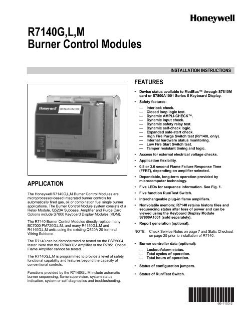
<strong>R7140G</strong>,L,M BURNER CONTROL MODULESTable 1. Flame Detection Systems. (Continued)Plug-in Flame Signal AmplifiersApplicable Flame DetectorsType Color Self-Checking ModelUltraviolet Purple No R7849A 0.8 or 3 Gas, oil Ultraviolet(Minipeeper)BlueDynamicR7849B c 0.8 or 3 Gas, oil UltravioletAmpli-Check ® (Minipeeper)DynamicSelf-CheckDynamicSelf-CheckR7861A b 0.8 or 3 Gas, oil,coalR7886A b 3 Gas, oil,coalOptical White DynamicR7851B 0.8 or 3 Gas, oil,Ampli-Check ® coalDynamicSelf-Checka Flame Failure Response Time (FFRT) depends on selection of amplifier.b Circuitry tests all electronic components in flame detection system (amplifier and detector) 12 times a minute during burneroperation and shuts down burner if detection system fails.c Circuitry tests flame signal amplifier 12 times a minute during burner operation and shuts down burner if amplifier fails.d Use C7027, C7035 and C7044 Flame Detectors only on burners that cycle on-off at least once every 24 hours. Use C7961 FlameDetector with R7851C Amplifier, C7061A Ultraviolet Detector with R7861A Amplifier or C7076A Flame Detector with R7886A Amplifieras ultraviolet flame detection system for appliances with burners that remain on continuously for 24 hours or longer.e R7847A,B Amplifiers with 0.8 second FFRT should not be used with C7012A,C Solid State Ultraviolet Detectors.f Order flame rod separately; see flame detector Instructions for holder.FlameFailureResponseTime (sec) a Fuel Type ModelsR7851C b 3 Gas, oil,coalUltravioletUltraviolet(AdjustableSensitivity)Optical (UV, IR,Visible Light)Optical (UV only)C7027, C7035, C7044 dC7027, C7035, C7044 dC7061C7076C7927, C7935, C7915,C7962C7961Table 2. Plug-in Purge Timer Cards.Pre-Purge TimingProduct Number7 ST7800A101330 ST7800A103940 ST7800A104760 ST7800A105490 ST7800A1062Above times cover the Purge timings of the R4140/50 Programmersand PM720.Other timings exist—consult the Tradeline catalog for completelist of ST7800 Purge timers.Accessories:The following accessories enhance the R7140 <strong>Burner</strong> <strong>Control</strong>Module and are available through local 7800 SERIESdistributors.Keyboard Display <strong>Modules</strong> (KDM):S7800A1001 English language.S7800A1035 French language.S7800A1043 German language.S7800A1050 Italian language.S7800A1068 Spanish language.S7800A1118 Katakana (Japanese) language.S7800A1126 Portuguese language.S7800A1142 English language.Communications:Q7700A1015 Network Interface Unit, 120 Vac, 50/60 Hzapplications, external modem required.Q7700B1004 Network Interface Unit with universal 100 to250 Vac, 50/60 Hz external power supply, externalmodem required.QS7800A1001 <strong>Control</strong>Bus Module, standard.QS7800B1000 <strong>Control</strong>Bus Module, multidrop.QS7850A1001 <strong>Control</strong>Bus Module, General PurposeInterface.ZM7850A1006 Combustion System Manager ® software.S7810A1009 Data <strong>Control</strong>Bus Module (if no KDM isused).S7810B1007 Data <strong>Control</strong>Bus Module, Multi-DropSwitch Module.S7810M1003 ModBus Module.Miscellaneous:S7820A1007 Remote Reset Module.S7830A1005 Expanded Annunciator, 120 Vac, 50/60 Hz.203541 Data <strong>Control</strong>Bus Connector, 5-wire.203765 Remote Display Mounting Bracket.221729 Dust cover, Relay Module.204718A Keyboard Display Module Cover, NEMA 4, clear.204718B Keyboard Display Module Cover, NEMA 1, clear.204718C Keyboard Display Module Cover, NEMA 4, clearwith reset button.205321 Flush Display mounting kit.221818A Extension Cable, display, 5 ft. (1524 mm).221818C Extension Cable, display, 10 ft. (3048 mm).FSP5004 Tester.123514A Rectification Flame Simulator.203659 Ultraviolet Flame Simulator.3 66-1153—2
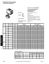
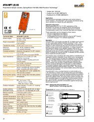
<strong>R7140G</strong>,L,M BURNER CONTROL MODULESBURNER CONTROL5(127)6-5/32(156)POWERPILOTFLAMEMAINALARMRESETS_+5-3/4 (146)1-1/4(32)5(127)7(177)M22604Fig. 2. Mounting dimensions of <strong>R7140G</strong>,L,M <strong>Burner</strong> <strong>Control</strong> Module with Q520A Subbase, in in. (mm).Table 3. Terminal Ratings.Terminal No. Description RatingsG Flame Sensor Earth Ground a —Earth G Earth Ground a —L2(N) Line Voltage Common —L1 Line Voltage Supply (L1) 120 Vac (+10/-15%), 50 or 60 Hz (±10%).3 Lockout/Running Interlock 120 Vac, 8A run, 43A inrush.4 Pre-Ignition Interlock Input 120 Vac, 1 mA.5 Pilot Valve/Ignition 120 Vac. See Table 4.6 Interrupted/Intermittent Pilot Valve/First Stage Oil Valve 120 Vac. See Table 4.7 Main Fuel Valve 120 Vac. See Table 4.8 <strong>Burner</strong> Motor 120 Vac, 9.8 AFL, 58.8 ALR (inrush).9 Alarm 120 Vac, 1A pilot duty.10 Firing Rate High Fire 120 Vac, 75 VA pilot duty.11 Firing Rate Common 120 Vac, 75 VA pilot duty.12 Firing Rate Modulate 120 Vac, 75 VA pilot duty.13 Low Fire Switch Input 120 Vac, 1 mA.14 Firing Rate Low Fire 120 Vac, 75 VA pilot duty.15 High Fire Switch Input 120 Vac, 1 mA.16 <strong>Burner</strong> <strong>Control</strong>ler and Limits 120 Vac, 1 mA.17 Shutter 120 Vac, 0.5A.18 Ignition 120 Vac, 4.5A ignition.F Flame Sensor 60 to 220 Vac, current limited.aThe R7140 must have an earth ground providing a connection between the subbase and the control panel or the equipment. The earthground wire must be capable of conducting the current to blow the 15A fast blow fuse (or breaker) in the event of an internal shortcircuit. The R7140 needs a low impedance ground connection to the equipment frame, which, in turn, needs a low impedanceconnection to earth ground.66-1153—2 4
<strong>R7140G</strong>,L,M BURNER CONTROL MODULESTable 4. Terminal Ratings.Terminal Typical Load Maximum Rating at 120 Vac, 60 Hz5 or 6 IgnitionTransformer/PilotValve/First Stage Fuel Valve7 Main Fuel Valve(s) (solenoid/motorized/diaphragm) andVent Valve, if required4.5A ignition and 50 VA pilot duty, or2.5A ignition and 75 VA pilot duty.250 VA pilot duty or 65 VA pilot duty in parallel with motorized valve(s) using a total of1150 VA locked rotor (inrush), 460 VA to open, and 250 VA to hold or motorized valve(s)using a total of 1500 VA locked rotor (inrush), 600 VA to open, and 250 VA to hold.Device Initiate Standby Purge Pilot<strong>R7140G</strong> 10 sec. * ** 4 or 10sec.Table 5. Sequence Timing for Normal Operation.FlameEstablishingPeriodMain10, 15sec. a orintermittent.R7140L 10 or 15sec. aR7140M10 sec. orintermittentRunPostPurgeTiming Interlock CircuitsFiringRateCircuit* 15 sec. Pre-Ignition,Running, Low Fire 4-wiremodulating NoPre-Ignition,Lockout High andLow FirePre-Ignition,Running, isolatedLow Fire.2-wireisolatedOn-Off-OncontactsEnergySavingPre-Purgea 30 seconds with JR2 clipped and jumper from terminal 8 to terminal 15.* STANDBY and RUN can be an infinite time period.** PURGE will be determined by which ST7800A purge card is selected; 15 timings are available from 2 seconds to 30 minutes.ApprovalCodeBodiesUL/CSAModulatingFM/IRIModulatingUL/CSAOn-Off.NOTE:Allowable inrush can be up to ten times the pilot dutyrating.EXAMPLE: Pilot duty rating = 50 VA.At 120 V, running current is:50/120 = 0.42A.Maximum allowable inrush is ten times 0.42A = 4.2A.INSTALLATIONWhen Installing this Product...1. Read these instructions carefully. Failure to followthem could damage the product or cause a hazardouscondition.2. Check the ratings given in the instructions and markedon the product to make sure the product is suitable forthe application.3. Installer must be a trained, experienced, flamesafeguard service technician.4. After installation is complete, check out the productoperation as provided in these instructions.WARNINGFire or Explosion Hazard.Can cause property damage, severe injury,or death.To prevent possible hazardous burner operation, verifysafety requirements each time a control is installed ona burner.WARNINGElectrical Shock Hazard.Can cause serious injury or death.Disconnect the power supply before beginninginstallation. More than one power supply disconnectmay be required.5 66-1153—2
<strong>R7140G</strong>,L,M BURNER CONTROL MODULESIMPORTANT1. Wiring connections for the relay modules are unique;therefore, refer to Fig. 4–11 or the correctSpecifications for proper subbase wiring, andsequence charts.2. Wiring must comply with all applicable codes,ordinances and regulations.3. Wiring must comply with NEC Class 1 (Line Voltage)wiring.4. Loads connected to the R7140 must not exceedthose listed in the Specifications; see Table 3 and 4.5. Limits and interlocks must be rated to simultaneouslycarry and break current to the ignition transformer,pilot valve, and main fuel valve(s).6. All external timers must be listed or componentrecognized by authorities who have jurisdiction forthe specific purpose for which they are used.7. For on-off gas-fired systems, some authorities whohave jurisdiction prohibit the wiring of any limit oroperating contacts in series between the flamesafeguard control and the main fuel valve(s).8. Two Flame Detectors can be connected in parallelwith the exception of flame detectors C7015, C7927,C7935, C7915, C7961, and C7962.9. This equipment generates, uses and can radiateradio frequency energy and, if not installed and usedin accordance with the instructions, may causeinterference to radio communications. It has beentested and found to comply with the limits for aClass B computing device of Part 15 of FCC ruleswhich are designed to provide reasonable protectionagainst such interference when operated in acommercial environment. Operation of thisequipment in a residential area may causeinterference; in which case, the users at their ownexpense may be required to take whatevermeasures are required to correct this interference.10.This digital apparatus does not exceed the Class Blimits for radio noise for digital apparatus set out inthe Radio Interference Regulations of the CanadianDepartment of Communications.LocationHumidityInstall the relay module where the relative humidity neverreaches the saturation point. The relay module is designed tooperate in a maximum 85 percent relative humiditycontinuous, noncondensing moisture environment.Condensing moisture may cause a safety shutdown.VibrationDo not install the relay module where it could be subjected tovibration in excess of 0.5G continuous maximum vibration.WeatherThe relay module is not designed to be weathertight.When installed outdoors, protect the relay module using anapproved weathertight enclosure.Mounting Wiring Subbase1. Mount the subbase in any position except horizontallywith the quadfurcated contacts pointing down. Thestandard vertical position is recommended. Any otherposition decreases the maximum ambient temperaturerating.2. Select a location on a wall, burner, or electrical panel.The Q520A can be mounted directly in the controlcabinet. Be sure to allow adequate clearance forservicing, installation, access or removal of the R7140,Expanded Annunciator, Keyboard Display Module,flame amplifier, flame amplifier signal voltage probes,Run/Test Switch, electrical signal voltage probes andelectrical field connections.3. For surface mounting, use the back of the subbase as atemplate to mark the four screw locations. Drill the pilotholes.4. Securely mount the subbase using four no. 6 screws.Wiring SubbaseWARNINGElectrical Shock Hazard.Can cause serious injury, death or equipmentdamage.Disconnect the power supply before beginninginstallation to prevent electrical shock, equipmentand control damage. More than one power supplydisconnect may be required.1. For proper subbase wiring, internal drawings, andsequence check charts, refer to Fig. 5, 6, 7, 8, 9 and 11.2. Disconnect the power supply from the main disconnectbefore beginning installation to prevent electrical shockand equipment damage. More than one disconnect maybe required.3. All wiring must comply with all applicable electricalcodes, ordinances and regulations. Wiring, whererequired, must comply with NEC, Class 1 (Line Voltage)wiring.a. Follow recommended wire size and type.b. Follow recommended grounding practices.4. Recommended wire routing of leadwires:a. Do not run high voltage ignition transformer wires inthe same conduit with the flame detector.b. Do not route flame detector leadwires in conduitwith line voltage circuits.c. Enclose flame detector leadwires without armorcable in metal cable or conduit.d. Follow directions in flame detector Instructions.5. Maximum wire lengths follow:a. R7140 leadwires—The maximum length of leadwireis 300 feet to terminal inputs (<strong>Control</strong>, Pre-IgnitionInterlock, Running/Lockout Interlock, High FireSwitch and Low Fire Switch).b. Flame Detector leadwires—The maximum flamesensor leadwire length is limited by the flame signalstrength.c. Remote Reset leadwires—The maximum length ofwire is 1000 feet to a Remote Reset push button.6. Make sure loads do not exceed the terminal ratings.Refer to the label on the R7140 or to the ratings in Table3 and 4.66-1153—2 6
<strong>R7140G</strong>,L,M BURNER CONTROL MODULESFinal Wiring Check1. Check the power supply circuit. The voltage andfrequency tolerance must match those of the R7140. Aseparate power supply circuit may be required for theR7140. Add the required disconnect means andoverload protection.2. Check all wiring circuits and complete the StaticCheckout, Table 8, before installing the R7140 on thesubbase.3. Install all electrical connectors.4. Restore power to the panel.Service Notes:Check the Q520 Wiring Subbase terminals against the typicalwiring drawings, Figures 7, 8, 12, 13, 17, or 18.If wires are attached to terminals that are unused in thefigures, DO NOT INSTALL THE R7140 until you haveidentified the connections’ functions. Most likely the oldsubbase terminals were used as tie points, so removing thewires, capping with a wire nut, and tucking the wire down intothe subbase is all that needs to be done.Make sure the wiring subbase of the old device is a20-terminal Q520 (four rows of 5 terminals).Make sure the system <strong>Control</strong>ler is connected to the correctterminal on the Q520 wiring subbase. It may be in a wire nuttucked into the subbase. It needs to be connected to aterminal (like terminal 4 or 16).Make sure there is an electrical service ground wireconnection to the G terminal in the wiring subbase.Replacing GP201 or GP301 devices:— High Fire (or Purge Rate) Switch may be connected toterminal D.— Identify, remove, and connect to terminal M.Replacing GP101 devices:— Check wiring subbase. If D is jumpered to 8, removethe jumper.Replacing R4140 programmers on Carlin 1050 and 1150burners:— Remove jumper from 6 to 7.— Remove jumper from L2 to 12 and wire nut the wirestogether. Note: There will be no wire on terminal 12.R4140M replacements:Check terminal 13 of the Q520 wiring subbase.— If nothing is on 13, install the new R7140M1007.— If 13 is jumpered to 8, remove the jumper and installR7140M1007.— If 13 goes somewhere (assume a low fire switchbecause the system has a damper motor), remove J1and J2 from the back of the R7140M1007.NOTE: J1 and J2 provide an input for the R7140M when thesystem does not have a spring return damper with alow fire switch.Leaving J1 and J2 in place with either 13 jumperedto 8 or with the low fire switch will cause the blowermotor to come on after the R7140M is installed andpower is supplied to the system.Generally, the following table will apply to select theR7140M1007 model and the status of jumpers J1and J2.Table 6. J1/J2 Jumper Configuration for R4140M/PM720M.Model Purge Timer Leave J1 & J2 Remove J1 and J2R4140M1004/M1012 A1039 XR4140M1020/M1038 A1047 XR4140M1046/M1053 A1062 XR4140M1079 (GP101) A1062 XR4140M1103/M1111 A1039 XR4140M1145/M1152 A1047 XR4140M1160/M1178 A1062 XR4140M1186 A1047 XR4140M1194ST7800A1062BC7000L1000 w/PM720M2002 ST7800A1062 XBC7000L1000 w/PM720M2036 * X* Check terminal 8 and 15.If jumpered, ST7800A1031 (7 second purge).If not jumpered, ST7800A1039 (30 second purge).7 66-1153—2
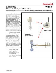
<strong>R7140G</strong>,L,M BURNER CONTROL MODULESMounting R7140 Relay ModuleInstalling the Programmer (Fig. 3)WARNINGElectrical Shock Hazard.Can cause severe injury, death or propertydamage.Disconnect power before installation to preventelectrical shock. More than one disconnect may beinvolved.1. Open the master switch.2. Make sure no subbase wiring is projecting out beyondthe terminal blocks. Tuck in wiring against the back ofthe subbase so it does not interfere with the contacts.3. Grasp the programmer chassis and engage the chassishinge brackets with the pivot pins at the bottom of thesubbase.4. Swing the chassis inward until the spring connectorsengage the knifeblade contacts. Push in until thecontacts are fully engaged.5. Tighten the chassis retaining screw securely.6. Close the master switch to restore power.Removing the Programmer1. Open the master switch.2. Loosen the chassis retaining screw.3. Pull outward on the top of the chassis.4. Disengage the chassis hinge brackets from the subbasepivot pins.WIRINGSUBBASEKNIFE-BLADECONTACTS (20)PIVOT PIN (2)HINGEBRACKET (2)SPRINGCONNECTORSCHASSISRETAININGSCREWPROGRAMMERCHASSISM22605Fig. 3. Mounting the programmer on the subbase.LEDDISPLAYINITIATE(INITIALPOWERUPONLY)POWER<strong>R7140G</strong>PREPURGE PFEPHOLD 10 SEC.00 TIMED 00DRIVE TO00(4 SEC. IF10 20 25 00 15STANDBY PREPURGE LOW FIRE JR1 CLIPPED MFEP RUN POSTPURGE STANDBYPOWER POWER POWER POWER POWER POWER POWER POWERPILOTFLAMEMAINALARMPILOTFLAMEMAINALARMPILOTFLAMEMAINALARMPILOTFLAMEMAINALARMPILOTFLAMEMAINALARMBURNERBURNER/BLOWER MOTOR818IGN.5 SEC.10 SEC. IGN./PILOT 515 SEC. INTERRUPTED PILOT VALVE61MAIN VALVE 7OPERATINGCONTROLSANDINTERLOCKSINTERLOCK. CHECKLIMITS AND BURNER CONTROLLER CLOSEDRUNNING INTERLOCKS CLOSEDL1 TO 1616 TO 333ICPII CLOSED24TO 16LOW FIRE SW.8 TO 13FLAMESIGNALSAFE START CHECKFLAME PROVINGSSCFIRINGRATEMOTOR<strong>R7140G</strong> SWITCHING10 TO 11MOTOR ACTION10 TO 1114 TO 1114 TO 111 TERMINAL 6 HAS THE FOLLOWING OPTIONS:2AS RECEIVED - INTERMITTENT PILOTJR2 CLIPPED - 15 SECOND MAIN FLAME ESTABLISHING PERIOD (INTERRUPTED PILOT)JR2 CLIPPED PLUS TERMINALS 8 - 15 JUMPERED - 30 SECOND MAIN FLAME ESTABLISHING PERIOD (INTERRUPTED PILOT)PII MEANS PRE-IGNITION INTERLOCK.3 FOR <strong>R7140G</strong>1000:L1 TO 44 TO 3Fig. 4. Operating sequence, <strong>R7140G</strong>1000/<strong>R7140G</strong>2008.M2331966-1153—2 8
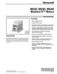
<strong>R7140G</strong>,L,M BURNER CONTROL MODULESL1(HOT)L2L1CONFIGURATIONJUMPERS1120 Vac,50/60 HzPLUG-IN PURGETIMER CARDFLAME SIGNALTESTJACKRUN/TESTSWITCHRESETPUSHBUTTONMICROCOMPUTER2KTESTPLUG-INFLAMEAMPLIFIERFG173KRELAYDRIVECIRCUIT4K5K6K7K8K9KRELAYSTATUSFEEDBACKAND LINEVOLTAGEINPUTSSTATUS LEDsSAFETY RELAYCIRCUIT1KPOWER SUPPLYCONTROLPOWERR1R1LIMITSDDLDDLCOMMUNICATIONSCONTROLLER6K13K1KEYBOARDDISPLAY MODULERS485123413PRE-IGNITIONINTERLOCKLOW FIRE SWITCHREMOTERESET8K18K29K2RUNNING/LOCKOUTINTERLOCK1K1 2K1 5K116 34K1HIGH FIRE10COMMON11MODULATE129K1LOW FIRE147K12K21856789IGNITIONPILOTPILOT/V2MAIN VALVEBLOWERALARMINDICATES FEEDBACK SENSINGOF RELAY CONTACT STATUSAND LINE VOLT INPUTSFIELD WIRINGINTERNAL WIRINGL21PROVIDE DISCONNECT MEANS AND OVERLOAD PROTECTION AS REQUIRED.M23320Fig. 5. Internal block diagram of the <strong>R7140G</strong>1000. (See Fig. 8 for detailed wiring.)9 66-1153—2
<strong>R7140G</strong>,L,M BURNER CONTROL MODULESL1(HOT)L2L1CONFIGURATIONJUMPERS1120 Vac,50/60 HzPLUG-IN PURGETIMER CARDFLAME SIGNALTESTJACKL2RUN/TESTSWITCHMICROCOMPUTERTESTPLUG-INFLAMEAMPLIFIERFG17PRE-IGNITIONINTERLOCKPOWER SUPPLYCONTROLPOWER4LIMITS CONTROLLER16RUNNING/LOCKOUTINTERLOCK31K1 2K1 5K118IGNITION4K15PILOT7K16PILOT/V26K113LOW FIRE SWITCH2K278MAIN VALVEBLOWER3K1HIGH FIRE129ALARM8K18K29K2COMMONMODULATE9K1LOW FIRE131514INDICATES FEEDBACK SENSINGOF RELAY CONTACT STATUSAND LINE VOLT INPUTSFIELD WIRINGINTERNAL WIRING1PROVIDE DISCONNECT MEANS AND OVERLOAD PROTECTION AS REQUIRED.M23321Fig. 6. Internal block diagram of the <strong>R7140G</strong>2008. (See Fig. 7 for detailed wiring.)66-1153—2 10
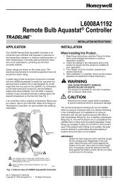
<strong>R7140G</strong>,L,M BURNER CONTROL MODULESFOR DIRECT SPARK IGNITION (OIL OR GAS)IGNITIONTRANSFORMER5TOL21ST STAGEFUEL VALVE62ND STAGEFUEL VALVE(OPTIONAL)7WIRING 2SUBBASETERMINALSTRIP (4)3PREIGNITIONINTERLOCK(S)3RUNNINGINTERLOCKS(INCLUDINGAIRFLOW SWITCH)5 SECOND IGNITION(EARLY SPARKTERMINATION)10 SECONDINTERRUPTEDPILOT/IGNITION54BURNERCONTROLLERLIMITSL1184PILOT/IGNITION617MAIN FUELVALVE(S)79120V ALARML216BURNER MOTOR(BLOWER)81011HIGH FIRECOMMON1215LOW FIRESTART SWITCHGBRWSERIES 90CONTROLLER1120V, 60 HZPOWERSUPPLYBRWSERIES 90FIRING RATEMOTORL1 (HOT)L2MODULATELOW FIREMASTERSWITCH13F14L24BLUEBLUEWHITEWHITERECTIFYING FLAMEROD, ORINFRARED(LEAD SULFIDE)FLAME DETECTORORC7027A, C7035A, ORC7044A ULTRAVIOLETFLAME DETECTORORC7012A, C, C7061, ORC7076A ULTRAVIOLETFLAME DETECTORWHITEYELLOW51234PROVIDE DISCONNECT MEANS AND OVERLOAD PROTECTIONAS REQUIRED.USE ALL NEC CLASS 1 WIRING.START INTERLOCKS IF USED BECOME PREIGNITION INTERLOCKS - (MUST REMAIN CLOSED UNTIL IGNITION TRIALS BEGIN.)TERMINAL 6 HAS THE FOLLOWING OPTIONS:AS RECEIVED - INTERMITTENT PILOTJR2 CLIPPED - 15 SECOND MAIN FLAME ESTABLISHING PERIODJR2 CLIPPED AND JUMPER FROM 8-15 - 30 SECOND MAIN FLAME ESTABLISHING PERIOD.5C7012E.F NEEDS TO BE UPDATED TO C7061.M22607BFig. 7. Wiring diagram for <strong>R7140G</strong>2008 for application replacing R4140G with start Interlock or BC7000L1000 withPM720G.11 66-1153—2
<strong>R7140G</strong>,L,M BURNER CONTROL MODULESFOR DIRECT SPARK IGNITION (OIL OR GAS)IGNITION5TOL26JUMPERWIRING2SUBBASETERMINALSTRIP (4)3PREIGNITIONINTERLOCK(S)RUNNINGINTERLOCKS(INCLUDINGAIRFLOW SWITCH)MAIN OIL VALVESOLENOID410 SECONDINTERRUPTEDPILOT/IGNITION7534BURNERCONTROLLERLIMITSL118PILOT/IGNITION6617MAIN FUELVALVE(S)79120V ALARML216BURNERMOTOR8BRW1011SERIES 90CONTROLLER1120V, 60 HZPOWERSUPPLYHIGH FIRECOMMONBRWSERIES 90FIRING RATEMOTORL1 (HOT)L2MODULATELOW FIREMASTERSWITCH1213F1514L26BLUEBLUEWHITEWHITE5LOW FIRESWITCHRECTIFYING FLAMEROD, ORINFRARED(LEAD SULFIDE)FLAME DETECTORORC7027A, C7035A, C7927 ORC7044A ULTRAVIOLETFLAME DETECTORORC7067A,D ORC7061 ULTRAVIOLETFLAMEDETECTOR 5GWHITEYELLOW1234PROVIDE DISCONNECT MEANS AND OVERLOAD PROTECTIONAS REQUIRED.USE ALL NEC CLASS 1 WIRING.FOR DIRECT SPARK IGNITION OF OIL, CONNECT IGNITION TOTERMINAL 5 AND MAIN OIL VALVE SOLENOID TO TERMINAL 7; JUMPERTERMINAL 7 T0 TERMINAL 6. SEE INSET.SOLENOID MUST NOT EXCEED THE ELECTRICAL RATINGS OF TERMINAL 7.45FOR THE C7015A INFRARED (LEAD SULFIDE) FLAME DETECTOR, EITHERLEADWIRE CAN BE CONNECTED TO THE F TERMINAL. RUN THE C7015ALEADWIRES ALONE IN CONDUIT ALL THE WAY TO THE WIRING SUBBASEAND GROUND THE CONDUIT AT THE SUBBASE. (REFER TO PUBLICATION60-2306 FOR DETAILED INSTRUCTIONS.)C7012 MUST BE UPDATED TO C7061.6 TERMINAL 6 HAS THE FOLLOWING OPTIONS:AS RECEIVED—INTERMITTENT PILOT.JR2 CLIPPED—15 SECOND INTERRUPTED PILOT.JR2 CLIPPED, TERMINALS 8-15 JUMPERED— 30 SECONDINTERRUPTED PILOT.M22608BFig. 8. Field wiring for <strong>R7140G</strong>1000 used for replacing R4140G Programmers with pre-ignition interlocks.66-1153—2 12
<strong>R7140G</strong>,L,M BURNER CONTROL MODULESLEDDISPLAYINITIATE(INITIALPOWERUPONLY)POWERR7140LPREPURGEPREPURGE PFEPHOLDHOLD 10 SEC.00DRIVE TO00 TIMED 00DRIVE TO00(4 SEC. IF10 20 25 00 15STANDBY HIGH FIRE PREPURGE LOW FIRE JR1 CLIPPED MFEP RUN POSTPURGE STANDBYPOWER POWER POWER POWER POWER POWER POWER POWER POWERPILOTFLAMEMAINALARMPILOTFLAMEMAINALARMPILOTFLAMEMAINALARMPILOTFLAMEMAINALARMPILOTFLAMEMAINALARMBURNERBURNER/BLOWER MOTOR818IGN.5 SEC.10 SEC. IGN./PILOT 515 SEC. PILOT 6MAIN VALVE 7OPERATINGCONTROLSANDINTERLOCKSLIMITS AND BURNER CONTROLLER CLOSEDLOCKOUT INTERLOCKS CLOSEDL1 TO 1616 TO 311PII CLOSED24TO 168TO 15HIGH FIRE SW.LOW FIRE SW.8 TO 13FLAMESIGNALSAFE START CHECKFLAME PROVINGSSCFIRINGRATEMOTORSWITCHING10 TO 11MOTOR ACTION10 TO 1110 TO 1410 TO 1412FOR R7140L1009:L1 TO 4.4 TO 3.PII MEANS PRE-IGNITION INTERLOCK.M23322Fig. 9. Operating sequence, R7140L1009 and R7140L2007.13 66-1153—2
<strong>R7140G</strong>,L,M BURNER CONTROL MODULESL1(HOT)L2L1CONFIGURATIONJUMPERS1120 Vac,50/60 HzPLUG-IN PURGETIMER CARDFLAME SIGNALTESTJACKRUN/TESTSWITCHRESETPUSHBUTTONMICROCOMPUTER2KTESTPLUG-INFLAMEAMPLIFIERFG173KRELAYDRIVECIRCUIT4K5K6K7K8K9KRELAYSTATUSFEEDBACKAND LINEVOLTAGEINPUTSSTATUS LEDsDDLDDLCOMMUNICATIONS1LIMITS CONTROLLERKEYBOARDDISPLAY MODULE16K13K1RS485234SAFETY RELAYCIRCUIT(D)HIGH FIRE SWITCHREMOTERESET1KPOWER SUPPLYCONTROLPOWERR1RUNNING/LOCKOUTPIIINTERLOCK1K1 2K1 5K11618(3)4K1LOW FIRE SWITCH51315(8)8K18K29K2HIGH FIRE10(X)COMMON11MODULATE (10)129K1(11)LOW FIRE14(12)PROVIDE DISCONNECT MEANS AND OVERLOAD PROTECTION AS REQUIRED.7K12K2678(M)9(A)R1INDICATES FEEDBACK SENSINGOF RELAY CONTACT STATUSAND LINE VOLT INPUTSFIELD WIRINGINTERNAL WIRINGIGNITIONPILOTPILOT/V2MAIN VALVEBLOWERALARML2NOTE: ( ) NUMBERS ON GP201, GP301 SUBBASE.M23323Fig. 10. Internal block diagram of the R7140L1009. (See Fig. 12 for detailed wiring.)66-1153—2 14
<strong>R7140G</strong>,L,M BURNER CONTROL MODULESL1(HOT)L2L1CONFIGURATIONJUMPERS1120 Vac,50/60 HzPLUG-IN PURGETIMER CARDFLAME SIGNALTESTJACKL2RUN/TESTSWITCHRESETPUSHBUTTONMICROCOMPUTER2KTESTPLUG-INFLAMEAMPLIFIERFG173KRELAYDRIVECIRCUIT4K5K6K7K8K9KRELAYSTATUSFEEDBACKAND LINEVOLTAGEINPUTSSTATUS LEDsSAFETY RELAYCIRCUITPRE-IGNITIONINTERLOCK1KPOWER SUPPLYCONTROLPOWER4LIMITSDDLDDLCOMMUNICATIONSCONTROLLER6K13K1KEYBOARDDISPLAY MODULERS485123161315RUNNING/LOCKOUTINTERLOCKLOW FIRE SWITCHHIGH FIRE SWITCHREMOTERESET8K18K29K21K1 2K1 5K134K17K12K2HIGH FIRE10COMMON11MODULATE129K1LOW FIRE141856789INDICATES FEEDBACK SENSINGOF RELAY CONTACT STATUSAND LINE VOLT INPUTSFIELD WIRINGINTERNAL WIRINGIGNITIONPILOTPILOT/V2MAIN VALVEBLOWERALARM1PROVIDE DISCONNECT MEANS AND OVERLOAD PROTECTION AS REQUIRED.M23329Fig. 11. Internal block diagram of the R7140L2007. (See Fig. 13 for detailed wiring.)15 66-1153—2
<strong>R7140G</strong>,L,M BURNER CONTROL MODULESFOR DIRECT SPARK IGNITION (OIL OR GAS)IGNITIONTRANSFORMER5TOL26JUMPERMAIN FUEL VALVE72WIRINGSUBBASETERMINALSTRIP (4)34PREIGNITIONINTERLOCKSBURNERCONTROLLERLIMITSLOCKOUTINTERLOCKS(INCLUDINGAIRFLOW SWITCH)L1185 SECOND IGNITION(EARLY SPARKTERMINATION)10 SECONDINTERRUPTEDPILOT/IGNITION15 SECONDINTERRUPTEDPILOT/IGNITION5469120V ALARML217167MAIN FUELVALVE(S)BURNER MOTOR(BLOWER)78BRW1011SERIES 90CONTROLLER1120V, 60 HZPOWERSUPPLYHIGH FIRECOMMONL1 (HOT)L2BRWSERIES 90FIRING RATEMOTORMODULATELOW FIREMASTERSWITCH1213F1514BLUEWHITEL24BLUEWHITELOW FIRESWITCHHIGH FIRESWITCHRECTIFYING FLAMEROD,ORINFRARED(LEAD SULFIDE)FLAME DETECTORC7027A, C7035A, ORC7044A ULTRAVIOLETFLAME DETECTORC7061, C7927 ORC7076A, DULTRAVIOLET 5FLAME DETECTOR6ORORWHITEYELLOWG1234POWER SUPPLY. PROVIDE DISCONNECT MEANS AND OVERLOADPROTECTION AS REQUIRED.USE ALL NEC CLASS 1 WIRING.FOR DIRECT SPARK IGNITION (OIL OR GAS) CONNECT THE IGNITIONTRANSFORMER AND MAIN FUEL VALVE(S) AS SHOWN IN INSET.FOR THE C7015A INFRARED (LEAD SULFIDE) FLAME DETECTOR, EITHERLEADWIRE CAN BE CONNECTED TO THE F TERMINAL. RUN THE C7015ALEADWIRES ALONE IN CONDUIT ALL THE WAY TO THE WIRING SUBBASEAND GROUND THE CONDUIT AT THE SUBBASE. (REFER TO PUBLICATION60-2306 FOR DETAILED INSTRUCTIONS.)567C7061 OR C7076 MUST BE RATED FOR 120 V, 60Hz. TWO DETECTORSWITH THE SAME MODEL NUMBER CAN BE WIRED IN PARALLEL TOTHE SAME TERMINALS. C7076A, D DOES NOT HAVE LEADWIRES. (FORINSTRUCTIONS, SEE FORM NUMBERS: 60-2046 FOR C7012A, C MODELSWITH ELECTRON TUBES; 60-2044 FOR C7012A,C,E,F SOLID STATEMODELS; 95-8269 FOR THE C7076A.)WHITE SHUTTER LEADWIRES ARE ONLY ON THE C7061A, EULTRAVIOLET FLAME DETECTORS; C7076A, D ADJUSTABLE SENSITIVITYULTRAVIOLET FLAME DETECTORS DO NOT HAVE LEADWIRES.TERMINAL 17 IS USED ONLY FOR THE SHUTTER ON SELF-CHECKINGC7061A, E, F OR C7076A, D FLAME DETECTORS.M22610Fig. 12. Sample block diagram of field wiring for the R7140L1009, used forreplacing R4140L Programmers with pre-ignition interlocks.66-1153—2 16
<strong>R7140G</strong>,L,M BURNER CONTROL MODULESFOR DIRECT SPARK IGNITION (OIL OR GAS)IGNITIONTRANSFORMER5TOL26JUMPERMAIN FUEL VALVE (S)7WIRING 2SUBBASETERMINALSTRIP (4)3PREIGNITIONINTERLOCKSLOCKOUTINTERLOCKS(INCLUDINGAIRFLOW SWITCH)5 SECOND IGNITION(EARLY SPARKTERMINATION)10 SECONDINTERRUPTEDPILOT/IGNITION54BURNERCONTROLLERLIMITSL11815 SECONDINTERRUPTEDPILOT69120V ALARML21716MAIN FUELVALVE(S)BURNER MOTOR(BLOWER)781011HIGH FIRECOMMON1215LOW FIRE STARTSWITCHHIGH FIREPURGE SWITCH3GBRWSERIES 90CONTROLLER120V, 60 HZPOWERSUPPLY121BRWSERIES 90FIRING RATEMOTORL1 (HOT)L2MODULATELOW FIREMASTERSWITCHPROVIDE DISCONNECT MEANS AND OVERLOADPROTECTION AS REQUIRED.USE ALL NEC CLASS 1 WIRING.13F14L24L1L2BLUEBLUEWHITEWHITEBLACKBLACKRECTIFYING FLAMEROD, RECTIFYINGPHOTOCELL, ORINFRARED(LEAD SULFIDE)FLAME DETECTORORC7027A, C7035A, ORC7044A ULTRAVIOLETFLAME DETECTORORC7012A, C, C7076A, ORC7061ULTRAVIOLETFLAME DETECTORWHITEYELLOWM22611B3IN SOME INSTALLATIONS THE LOW FIRE INTERLOCK IS BETWEENTERMINALS L1 AND 13.4C7076 COMES WITHOUT LEADWIRES; C7061 DOES NOT HAVE BLACK LEADWIRES.Fig. 13. Block diagram of field wiring for the R7140L2007, used for replacingBC7000L1000 with PM720L.17 66-1153—2
<strong>R7140G</strong>,L,M BURNER CONTROL MODULESLEDDISPLAYINITIATE(INITIALPOWERUPONLY)POWERR7140MPREPURGE PFEPHOLD 10 SEC.00 TIMED 00DRIVE TO00(4 SEC. IF10 20 25 00 15STANDBY PREPURGE LOW FIRE JR1 CLIPPED MFEP RUN POSTPURGE STANDBYPOWER POWER POWER POWER POWER POWER POWER POWERPILOTFLAMEMAINALARMPILOTFLAMEMAINALARMPILOTFLAMEMAINALARMPILOTFLAMEMAINALARMPILOTFLAMEMAINALARMBURNERBURNER/BLOWER MOTOR818IGN.5 SEC.10 SEC. IGN./PILOT 5INTERMITTENT PILOT VALVE6MAIN VALVE 7OPERATINGCONTROLSANDINTERLOCKSLIMITS AND BURNER CONTROLLER CLOSEDRUNNING INTERLOCKS CLOSEDL1 TO16 TO4333PII CLOSED24TO 16LOW FIRE SW.8 TO 13FLAMESIGNALSAFE START CHECKFLAME PROVINGSSCR7140M SWITCHING 110 TO L210 TO L2DAMPERMOTORMOTOR ACTION1 WHEN USING A SPRING RETURN ACTUATOR MOTOR, REMOVE J1 AND J2 JUMPERS LOCATED ON R7140M SUBBASE.23PII MEANS PRE-IGNITION INTERLOCK.R7140M WHEN USED AS BC7000 REPLACEMENT ON R4140 WITH START INTERLOCKS L1 TO 16.M23331Fig. 14. Operating sequence, R7140M.66-1153—2 18
<strong>R7140G</strong>,L,M BURNER CONTROL MODULESL1L2L117PURGETIMERCONFIGURATIONJUMPERSL2FGFLAMEAMPLIFIERINTERNALELECTRONICS3K19ALARM1R1STARTINTERLOCKSLIMITS16CONTROLLERAIRFLOW4311J1128K29K1109K2141K113J26K1LF2K185K14K17K12K2185671R1BLOWERIGN XFMRINTERMITTENTPILOT15 SECONDINTERMITTENTPILOT VALVEMAIN VALVEM23335Fig. 15. Internal block diagram of the R7140M1007 with start interlocks. (See Fig. 17 for detailed wiring.)L1L2L117PURGETIMERCONFIGURATIONJUMPERSL2FGFLAMEAMPLIFIERINTERNALELECTRONICS3K19ALARM1R1PRE-IGNITION16LIMITS4CONTROLLER AIRFLOWJ1311128K29K1109K2141K113J26K1LF2K185K14K17K12K2185671R1BLOWERIGN XFMRINTERMITTENTPILOT15 SECONDINTERMITTENTPILOT VALVEMAIN VALVEM23336Fig. 16. Internal block diagram of the R7140M1007 with pre-ignition interlocks. (See Fig. 18 for detailed wiring.)19 66-1153—2
<strong>R7140G</strong>,L,M BURNER CONTROL MODULESFOR DIRECT SPARK IGNITION OF OIL OR GASIGNITION5TOL21ST STAGEFUEL VALVE6WIRING 2SUBBASETERMINALSTRIP (4)343RUNNINGINTERLOCKS(INCLUDINGAIRFLOW SWITCH)2ND STAGEFUEL VALVE(OPTIONAL)5 SECOND IGNITION(EARLY SPARKTERMINATION)74BURNERCONTROLLERLIMITSL11810 SECONDINTERRUPTEDPILOT/IGNITION517INTERMITTENTPILOT69120V ALARML216MAIN FUELVALVE(S)71011120V, 60 HZPOWERSUPPLY12345671DAMPERCONTROLL1 (HOT)L25MASTERSWITCHPOWER SUPPLY. PROVIDE DISCONNECT MEANS ANDOVERLOAD PROTECTION AS REQUIRED.USE ALL NEC CLASS 1 WIRING.START INTERLOCKS IF USED BECOME PRE-IGNITIONINTERLOCKS (MUST REMAIN CLOSED UNTIL IGNITION TRIALS BEGIN.)PM720M 16 TO 4 IS A PRE-IGNITION INTERLOCK.USE 2 POSITION SPRING RETURN MOTOR.WHITE LEADWIRES ON C7012 U.V. FLAME DETECTORS. REPLACE C7012WITH C7061 UV DETECTOR AND R7861A1026 AMPLIFIER.MAKE SURE CONNECTOR IS ON TERMINAL 16.1213F8L27L1L21514BLUEBLUEWHITEWHITEBLACKBLACKBURNER MOTORLOW FIRESTART SWITCHRECTIFYING FLAMEROD, RECTIFYINGPHOTOCELL, ORINFRARED(LEAD SULFIDE)FLAME DETECTORORC7027A, C7035A, ORC7044A ULTRAVIOLETFLAME DETECTORORC7012A, C, E, OR FULTRAVIOLETFLAME DETECTOR68GWHITEYELLOW8REMOVE J1 AND J2 JUMPERS ON R7140M IF LOW FIRE SWITCH OR A JUMPERIS CONNECTED BETWEEN 8 AND 13.Fig. 17. R7140M1007 used on applications replacing R4140M Programmers with Start Interlocks or BC7000 withPM720M.66-1153—2 20
<strong>R7140G</strong>,L,M BURNER CONTROL MODULES4FOR DIRECT SPARK IGNITION (OIL OR GAS)IGNITIONTRANSFORMER5TOL21ST STAGEFUEL VALVE62ND STAGEFUEL VALVE(OPTIONAL)7WIRING2SUBBASETERMINALSTRIP (4)3(P)PREIGNITIONINTERLOCKS7RUNNINGINTERLOCKS(INCLUDINGAIRFLOW SWITCH)5 SECOND IGNITION(EARLY SPARKTERMINATION)10 SECONDINTERRUPTEDPILOT/IGNITION544(13)BURNERCONTROLLERLIMITSL118INTERMITTENTPILOT/IGNITION69(A)ALARML2176MAIN FUELVALVE(S)710(X)DAMPERCONTROL312(11)16(3)BURNERMOTOR8(M)11(10)13(D)15(8)LOW FIRESWITCHG(S2)1120V, 60 HZPOWERSUPPLYL1 (HOT)L2MASTERSWITCHF(S1)14(12)RECTIFYING FLAMEROD ORINFRARED(LEAD SULFIDE) 5FLAME DETECTOROR12POWER SUPPLY. PROVIDE DISCONNECT MEANSAND OVERLOAD PROTECTION AS REQUIRED.USE ALL NEC CLASS 1 WIRING.BLUEC7027A, C7035A, ORC7044A ULTRAVIOLETFLAME DETECTORORWHITE345WHEN USING A 2-POSITION SPRING DAMPER MOTOR, CLIPAND REMOVE J1 AND J2, LOCATED ON R7140 SUBBASE.FOR DIRECT SPARK IGNITION (OIL OR GAS), CONNECT THE IGNITIONAND MAIN FUEL VALVE(S) AS SHOWN IN THE INSET.FOR THE C7015A INFRARED (LEAD SULFIDE) FLAME DETECTOR, EITHERLEADWIRE MAY BE CONNECTED TO THE F TERMINAL. RUN THE C7015ALEADWIRES ALONE IN CONDUIT ALL THE WAY TO THE WIRING SUBBASEAND GROUND THE CONDUIT AT THE SUBBASE. (REFER TO PUBLICATION60-2306 FOR DETAILED INSTRUCTIONS.)L2BLUEWHITEWHITEC7061, C7012A, C,ULTRAVIOLETFLAME DETECTORNOTE: ( ) NUMBERS ON GP101 SUBBASE.6YELLOW6WHITE SHUTTER LEADWIRES ARE ONLY ON THE C7061A OR F ORC7961 E, OR F ULTRAVIOLET FLAME DETECTORS WITH SELF-CHECKINGFEATURE; TERMINAL 17 IS NOT USED FOR OTHER DETECTORS. (REFERTO PUBLICATION 60-2358 FOR DETAILED INSTRUCTIONS.)7REPLACEMENT R7140M. START INTERLOCK BECOMES PRE-IGNITION INTERLOCK.M23338Fig. 18. Block diagram of field wiring for the R7140M1007, used for replacing R4140M Programmers with Pre-IgnitionInterlocks.21 66-1153—2
<strong>R7140G</strong>,L,M BURNER CONTROL MODULESSAFETY SHUTDOWNSafety Shutdown (Lockout) occurs if any of thefollowing occur during the indicated period:1. INITIATE Period:a. Purge card is not installed or is removed.b. Purge card is bad.c. Configuration jumpers are changed (after 200 hoursof operation).d. AC line power errors occur; see Operation section.e. Four minute INITIATE period has been exceeded.2. STANDBY Period:a. Flame signal is present after 240 seconds.b. Pre-Ignition Interlock is open an accumulative timeof 30 seconds.c. Interlock check feature is enabled and theInterlock String (including airflow switch) is closedfor 120 seconds with controller closed.d. Ignition/pilot valve/intermittent pilot valve terminal isenergized.e. Main valve terminal is energized.f. Internal system fault occurs.g. Purge card is not installed or is removed.h. Purge card is bad.3. PREPURGE Period:a. Pre-Ignition Interlock opens anytime duringPREPURGE period (R7140L).b. Flame signal is detected after first ten secondsduring PREPURGE (R7140L).c. High Fire Switch fails to close within 4 minutes and15 seconds after the firing rate motor is commandedto drive to the high fire position at the start ofPREPURGE (R7140L).d. Low Fire Switch fails to close within 4 minutes and15 seconds after the firing rate motor is commandedto drive to the low fire position at the end ofPREPURGE.e. Running Interlock does not close within 30 seconds(<strong>R7140G</strong>,M).f. Lockout Interlock does not close within 10 seconds(R7140L).g. Lockout Interlock opens during PREPURGE (R7140L).h. Ignition/pilot valve/intermittent pilot valve terminal isenergized.i. Main valve terminal is energized.j. Internal system fault occurs.k. Purge card is removed.l. Purge card is bad.4. PILOT FLAME ESTABLISHING Period (PFEP):a. Low Fire Switch opens.b. Lockout Interlock opens (RM7140L).c. Ignition/pilot valve/intermittent pilot valve terminal isnot energized.d. Early spark termination terminal is energized afterfive seconds.e. No flame is present at the end of PFEP.f. Main valve terminal is energized (<strong>R7140G</strong>,M).g. Internal system fault occurs.h. Purge card is removed.i. Purge card is bad.5. MAIN FLAME ESTABLISHING Period (MFEP):a. Low Fire Switch Opens.b. Lockout Interlock opens (R7140L).c. Ignition/pilot valve/intermittent pilot valve terminal isnot energized.d. Main valve terminal is not energized.e. No flame is present at the end of MFEP.f. Internal system fault occurs.g. Purge card is removed.h. Purge card is bad.6. RUN Period:a. No flame is present.b. Lockout Interlock opens (R7140L).c. Interrupted pilot valve terminal is energized(<strong>R7140G</strong>,M).d. Main valve terminal is not energized.e. Internal system fault occurs.f. Purge card is removed.g. Purge card is bad.7. POSTPURGE Period:a. Pre-Ignition Interlock does not close in five secondsand opens after five-second time period.b. Ignition/pilot valve/intermittent pilot valve terminal isenergized.c. Main valve terminal is energized.d. Internal system fault occurs.e. Purge card is removed.f. Purge card is bad.OPERATIONSequence of OperationThe R7140 has the following operating sequences; see Fig. 4,9, and 14. The R7140 LED provides positive visual indicationof the program sequence: POWER, PILOT, FLAME, MAINand ALARM.InitiateThe R7140 enters the INITIATE sequence when the RelayModule is powered. The R7140 can also enter the INITIATEsequence if the Relay Module verifies voltage fluctuations of+10/-15 percent or frequency fluctuations of ±10 percentduring any part of the operating sequence. The INITIATEsequence lasts for ten seconds unless the voltage orfrequency tolerances are not met. When the tolerances arenot met, a hold condition is initiated for at least five seconds.When the tolerances are met, the INITIATE sequencerestarts. If the condition is not corrected and the hold conditionexists for four minutes, the R7140 locks out. Causes for holdconditions in the INITIATE sequence:a. AC line dropout is detected.b. AC line noise prevents a sufficient reading of theline voltage inputs.c. Low line voltage brownouts occur.The INITIATE sequence also delays the burner motor starterfrom being energized and de-energized from an intermittentAC line input or control input.StandbyThe R7140 is ready to start an operating sequence when theoperating control determines a call for heat is present. Theburner switch, limits, operating control and all microcomputermonitored circuits must be in the correct state for the R7140 tocontinue into the PREPURGE sequence.66-1153—2 22
<strong>R7140G</strong>,L,M BURNER CONTROL MODULESNormal Start-Up Pre-PurgeThe R7140 provides a pre-purge timing selectable from twoseconds to 30 minutes with power applied and the R7140operating control indicating a call for heat:NOTE:NOTE:a. Running Interlocks, Pre-Ignition Interlocks, <strong>Burner</strong>Switch, Run/Test Switch, Lockout Interlocks and allmicrocomputer monitored circuits must be in thecorrect operating state.b. The blower motor output, terminal 8, is powered tostart the PREPURGE sequence. The PREPURGEtiming for the R7140L does not begin until the HighFire Switch is closed.A jumpered High Fire Switch adds a 30-second holdbefore the purge time starts.c. The Pre-Ignition Interlock input must remain closedthroughout PREPURGE; otherwise, control returns tothe STANDBY state and holds (30 seconds) for the<strong>R7140G</strong>,M or safety shutdown for the R7140L occurs.d. The Lockout Interlock or Running Interlock inputs(interlock circuit including Airflow Switch) must closeby ten seconds into PREPURGE; otherwise, arecycle to the beginning of PREPURGE for the<strong>R7140G</strong>,M will happen or a safety shutdown for theR7140L occurs.e. When PREPURGE timing is complete, the firing ratemotor drives to the low fire position. If a dampermotor is used (R7140M), jumpers J1 and J2 shouldbe removed from R7140 subbase.f. When the firing rate motor reaches low fire position,the Low Fire Switch, terminal 13, is energized toenter the Ignition Trial state.A 30-second hold occurs for a jumpered Low FireSwitch before the ignition trial period begins.Ignition Trials1. Pilot Flame Establishing Period (PFEP):a. With the firing rate motor at the low fire position:(1) The pilot valve and ignition transformer,terminals 5, 6, and 18, are energized.(a) The <strong>R7140G</strong> has an interrupted orintermittent pilot valve, terminal 6, dependingon the selection of configuration jumper 2.(b) The R7140L has a 15-second interruptedpilot valve, terminal 6.(c) The R7140M has an intermittent pilot valve,terminal 6.NOTE: All of the R7140s have a ten-second interrupted pilotvalve/ignition, terminal 5.(2) During PFEP, the Low Fire Switch must remainclosed. If it opens, a safety shutdown occurs.(3) The Pre-Ignition Interlock input is ignoredthroughout the Ignition Trial state.b. Flame must be proven by the end of the 10-secondPFEP (four if JR1 is clipped) to allow the sequenceto continue. If flame is not proven by the end ofPFEP, a safety shutdown occurs.c. After five seconds, the ignition, terminal 18, isde-energized for early spark termination.2. Main Flame Establishing Period (MFEP):a. Terminal 7 is energized when the presence of flame isverified at the end of a 10-second Pilot Flame EstablishingPeriod (PFEP) (four seconds if JR1 is clipped).b. Terminal 5 is turned off 10 seconds after terminal 7is energized.c. Terminal 6 action:(1) R7140L: De-energized 15 seconds after terminal7 is energized.(2) <strong>R7140G</strong>:(a) Not turned off, or(b) 15 seconds after terminal 7 is energized andJR2 is clipped, or(c) 30 seconds after terminal 7 is energized andterminals 8 and 15 are jumpered and jumperJR2 is clipped.(3) R7140M: Remain energized as long as call forheat is present.Run1. Fifteen seconds after the main valve terminal 7 isenergized and flame is maintained, the R7140 goes toRun.2. The firing rate motor releases to modulation(<strong>R7140G</strong>,L). Damper motor is energized (R7140M).3. The R7140 is now in RUN and remains in RUN until thecontroller input, terminal 16 or 4 (model dependent),opens, indicating that the demand is satisfied or a limitopened.PostpurgeThe R7140 provides a 15-second POSTPURGE following thecompletion of the RUN period (call for heat ends). The blowermotor output remains powered to drive all products ofcombustion and any unburned fuel from the combustionchamber. It also supplies combustion air to burn fuel beingpurged from the fuel line downstream of the fuel shutoff valve.1. The main fuel valve and intermittent pilot valve,terminals 7 and 6, are de-energized and the firing ratemotor is commanded to the low fire position to begin thePOSTPURGE period.2. After the 15-second POSTPURGE period is completed,the blower motor (terminal 8) is de-energized and theR7140 reenters Standby.Run/Test SwitchWARNINGExplosion Hazard.Can cause serious injury or death.Do not use the Run/Test switch during the Pilot FlameEstablishing Period for the R7140 when using DirectSpark Function, because it turns on the main gasvalve, causing an accumulation of fuel in the burner.The Run/Test Switch is located on the top side of the R7140,see Fig. 1. The Run/Test Switch allows the burner sequenceto be altered as follows:23 66-1153—2
<strong>R7140G</strong>,L,M BURNER CONTROL MODULES1. In Pre-Purge Drive To High Fire Position (R7140L), theRun/Test Switch, when placed in the TEST position,holds in PREPURGE with the firing rate motor in theHigh Fire position.2. In the measured PREPURGE sequence, the Run/TestSwitch, when placed in the TEST position, causes thePREPURGE timing to stop. The firing rate motor is inthe High Fire position.3. In Pre-Purge Drive to Low Fire position, the Run/TestSwitch, when placed in the TEST position, holds theburner sequence in PREPURGE with the firing ratemotor in the Low Fire position.4. In PFEP, the Run/Test Switch, when placed in the TESTposition, stops the timer during the first 8 seconds when a10-second PFEP is selected or during the first 3 secondswhen a 4-second PFEP is selected, allowing pilot-turndowntest and other burner adjustments to be made. Thisactivates a 15-second flameout timer that permits pilotflame adjustment without nuisance safety shutdowns. TheRun/Test Switch is ignored during PFEP for the R7140L ifterminals 5 and 7 or 7 and 6 are jumpered.5. During Run, the Run/Test Switch, when placed in theTEST position, drives the firing rate motor to the LowFire position.SETTINGS AND ADJUSTMENTSSelectable Site-Configurable JumpersThe R7140 has three site-configurable jumper options; seeFig. 19 and Table 7. If necessary, clip the site-configurablejumpers with side cutters and remove the resistors from theRelay Module.The R7140M has two additional jumpers located on the backof the chassis. These must be cut if a spring return dampermotor is used.SELECTABLE CONFIGURATION JUMPERSRUN/TEST SWITCHNOTE:When R7140 is switched to the Test mode, it stops andholds at the next Run/Test Switch point in the operatingsequence. Make sure that the Run/Test Switch is in theRUN position before leaving the installation.Table 7. Site Configurable Jumper Options.NOTE: CONFIGURATION JUMPERS SHOWN FOR RM7800G/RM7840G.M12301Fig. 19. Selectable site-configurable jumpers.Jumper Number Description Intact Clipped RM7800/RM7840 TypeJR1Pilot Flame Establishing 10 seconds 4 seconds AllPeriod (PFEP)JR2Pilot Valve a /Main Flame 10 seconds 15 or 30 seconds Interrupted b <strong>R7140G</strong>Establishing Period (MFEP) IntermittentJR3 Start-up Interlock Check Disabled Enabled Alla Pilot Valve/First Stage Oil Valve (Valve/Start) terminal 6.b A 30 second MFEP can be accomplished by adding a jumper wire between terminals 15 and 8.SERVICE NOTE: Clipping and removing these site-configurable jumpers enhances the level of safety. Removal after 200 hoursof main valve operation will result in a hard lockout, Code 110.66-1153—2 24
<strong>R7140G</strong>,L,M BURNER CONTROL MODULESSTATIC CHECKOUTAfter checking all wiring, perform this checkout beforeinstalling the R7140 on the subbase. These tests verify theQ520A Wiring Subbase is wired correctly, and the externalcontrollers, limits, interlocks, actuators, valves, transformers,motors and other devices are operating properly.WARNINGExplosion and Electrical Shock Hazard.Can cause serious injury, death, or equipmentdamage.1. Close all manual fuel shutoff valve(s) before startingthese tests.2. Use extreme care while testing the system. Linevoltage is present on most terminal connectionswhen power is on.3. Open the master switch before installing orremoving a jumper on the subbase.4. Before continuing to the next test, be sure toremove test jumper(s) used in the previous test.5. Replace all limits and interlocks that are not operatingproperly. Do not bypass limits and interlocks.CAUTIONEquipment Damage Hazard.Improper testing can damage equipment.Internal surge protectors can break down and conducta current, causing the R7140 to fail the dielectric testor possibly destroy the internal lightning and highcurrent protection. Do not perform a dielectric test withthe R7140 installed.Equipment Recommended1. Voltmeter (1M ohm/volt minimum sensitivity) set on the0-300 Vac scale.2. Two jumper wires; no. 14 wire, insulated, 12 inches(304.8 mm) long with insulated alligator clips at both ends.3. When jumpered to Ignition, Pilot and Main Valves, useammeter in series and verify proper current draw.General Instructions1. Perform all applicable tests listed in Static Checkout,Table 8, in the order listed.2. Make sure all manual fuel shutoff valve(s) are closed.3. Perform only those tests designated for the specificR7140 model being tested.4. Raise the setpoint of the operating controller to simulatea call for heat.5. For each test, open the master switch and install thejumper wire(s) between the subbase wiring terminalslisted in the Test Jumpers column.6. Close the master switch before observing operation.7. Read the voltage between the subbase wiring terminalslisted in the Voltmeter column.8. If there is no voltage or the operation is abnormal, checkthe circuits and external devices as described in the lastcolumn.9. Check all wiring for correct connections, tight terminalscrews, correct wire, and proper wiring techniques.Replace all damaged or incorrectly sized wires.10. Replace faulty controllers, limits, interlocks, actuators,valves, transformers, motors and other devices asrequired.11. Make sure normal operation is obtained for eachrequired test before continuing the checkout.12. After completing each test, be sure to remove the testjumper(s).WARNINGExplosion Hazard.Can cause serious injury or death.Make sure all manual fuel shutoff valves are closedbefore performing static checkout.TestNo.R7140 ModelsTestJumpers VoltmeterTable 8. Static Checkout.Normal OperationIf Operation is Abnormal,Check the Items Listed Below1 All None L1-L2 Line voltage at terminal L1. 1. Master Switch.2. Power connected to the Master Switch.3. Overload protection (fuse, circuit breaker,etc.) has not opened the power line.2 16-L2 Line voltage at terminal 16 (4 onPre-Ignition Interlock devices).1. Limits.2. <strong>Burner</strong> <strong>Control</strong>ler.3 4-L2 Line voltage at terminal 16. 1. Pre-Ignition interlocks.4 L1-8 3-L2 1. <strong>Burner</strong> motor (fan orblower) starts.2. Line voltage at terminal 3within 10 seconds.5 L1-18 — Ignition spark (if ignitiontransformer is connected toterminal 18).1. <strong>Burner</strong> motor circuit.a. Manual switch of burner motor.b. <strong>Burner</strong> motor power supply, overloadprotection, and starter.c. <strong>Burner</strong> motor.2. Running or Lockout Interlocks (includingAirflow Switch).1. Watch for spark or listen for buzz.a. Ignition electrodes are clean.b. Ignition transformer is okay.25 66-1153—2
<strong>R7140G</strong>,L,M BURNER CONTROL MODULESTestNo.R7140 Models6 All L1-5 — 1. Ignition spark (if ignitiontransformer is connected toterminal 5).2. Automatic pilot valve opens (ifconnected to terminal 5).NOTE:Refer to wiring diagramof system being tested.7 L1-6 — Same as test no. 6 forconnections to terminal 5. Ifusing direct spark ignition, checkthe first stage fuel valve(s)instead of the pilot valve.8 L1-7 — Automatic main fuel valve(s)open.If using direct spark ignition on amodel with intermittent pilot onterminal 6, check the optionalsecond stage fuel valve, if used.9 L1-9 — Alarm (if used) turns on. 1. Alarm.10 <strong>R7140G</strong>,L L1-8and10-1111 <strong>R7140G</strong>,L L1-8and14-1112 <strong>R7140G</strong>,L L1-8and10-1113 R7140L L1-8and14-1113-L2 Firing rate motor drives open;zero volts at terminal 13 aftermotor starts driving open.13-L2 Firing rate motor drives closed;line voltage at terminal 13 aftermotor is in Low Fire position.15-L2 Firing rate motor drives open;line voltage at terminal 15 aftermotor is in High Fire position.15-L2 Firing rate motor drives closed;zero volts at terminal 15 aftermotor starts driving closed.14 <strong>R7140G</strong>,L 11-12 — 1. Raise setpoint of Series 90controller—firing rate motorshould drive toward open.2. Lower setpoint of Series 90controller—firing rate motorshould drive toward closed.15 R7140M withopen dampercontacts.16 R7140M withopen dampercontacts.17 R7140M withopen dampercontacts.Final AllTestJumpers Voltmeter14-11 — If damper motor is used, motordrives damper open.L1-8 13-L2 If damper motor is used, motordrives open; line voltage atterminal 13 after motor is in LowFire position.L1-8andL1-11Table 8. Static Checkout. (Continued)Normal Operation13-L2 If damper motor is used, motordrives open; zero volts atterminal 13.If Operation is Abnormal,Check the Items Listed Below1. Watch for spark or listen for buzz.a. Ignition electrodes are clean.b. Ignition transformer is okay.2. Listen for click or feel head of valve foractivation.a. Actuator, if used.b. Pilot valve.Same as test no. 6. If using direct sparkignition, check the first stage fuel valve(s)instead of the pilot valve.1. Listen for and observe operation of themain fuel valve(s) and actuator(s).2. Valve(s) and actuator(s).1. Low Fire Start Switch.2. Firing rate motor and transformer.1. Low Fire Start Switch.2. Firing rate motor and transformer.1. High Fire Purge Switch.2. Firing rate motor and transformer.1. Low Fire Start Switch.2. Firing rate motor and transformer.1. Series 90 <strong>Control</strong>ler.2. Firing rate motor and transformer.Damper motor.1. Low Fire Start Switch.2. Damper motor.1. Low Fire Start Switch.2. Damper motor.CAUTIONEquipment Damage Hazard.Improper wiring can damage equipment.On completing these tests, open the master switch and remove all test jumpers from thesubbase terminal. Also remove bypass jumpers from the low fuel pressure limits (if used) toprevent equipment damage.66-1153—2 26
<strong>R7140G</strong>,L,M BURNER CONTROL MODULESSYSTEM CHECKOUTIMPORTANTPerform all Static Checkout Procedures in theapplicable relay module installation instructionsbefore starting these procedures.WARNINGExplosion Hazard.Can cause serious injury or death.Do not allow fuel to accumulate in the combustionchamber for longer than a few seconds without ignitingto prevent danger of forming explosive mixture.Close manual fuel shutoff valve(s) if flame is notburning at end of specified time.WARNINGElectric Shock Hazard.Can cause serious injury or death.1. Use extreme care while testing system. Line voltageis present on most terminal connections whenpower is on.2. Open master switch before removing or installingR7140 Relay Module.Make sure all manual fuel shutoff valve(s) are closed beforestarting initial lightoff check and Pilot Turndown tests.Do not put the system in service until you have satisfactorilycompleted all applicable tests in this section and any othersrecommended by the original equipment manufacturer.Limit trial for pilot to ten seconds. Limit the attempt to lightmain burner to two seconds after fuel reaches burner nozzle.Do not exceed manufacturer nominal lightoff time.CAUTIONEquipment Malfunction or Damage Hazard.<strong>Inc</strong>orrect wiring can cause equipment damage.Each relay module type is unique. Using existingwiring on a relay module change can cause equipmentdamage.IMPORTANT1. If the system fails to perform properly, refer to theTroubleshooting section.2. Repeat all required Checkout tests after alladjustments are made. All tests must be satisfiedwith the flame detector(s) in their final position.Equipment RecommendedS7800A Keyboard Display ModuleVolt-ohmmeter (1M ohm/volt minimum sensitivity) with:• 0-300 Vac capability.• 0-6000 ohm capability.• 0-10 Vdc capability.Checkout SummaryTable 9 provides an overview of checkout steps performed foreach applicable system.See Installation Instructions for location of component partsand terminal locations.Table 9. Checkout Steps and Applicable Detection Systems.Checkout StepPilotedSystems DSI SystemsInfrared FlameDetectorsFlame RodSystemsUltravioletFlame DetectorsPreliminary Inspection X X X X XFlame Signal Measurement X X X X XInitial Lightoff Check for Proved PilotXInitial Lightoff Check for Direct Spark IgnitionXPilot Turndown TestXIgnition Interference TestXHot Refractory Saturation TestXHot Refractory Hold-in Test X X X X XIgnition Spark PickupXResponse to Other Ultraviolet SourcesXFlame Signal with Hot Combustion Chamber X X X X XSafety Shutdown Tests X X X X XPreliminary InspectionPerform the following inspections to avoid common problems.Make certain that:1. Wiring connections are correct and all terminal screwsare tight.2. Flame detector(s) is clean, installed and positionedproperly. Consult the applicable Instructions.3. Combination of amplifier and flame detector(s) iscorrectly used. See the amplifier specifications.4. Plug-in amplifier and purge card (if required) aresecurely in place.5. <strong>Burner</strong> is completely installed and ready to fire; consultequipment manufacturer instructions. Fuel lines arepurged of air.6. Combustion chamber and flues are clear of fuel and fuelvapor.27 66-1153—2
<strong>R7140G</strong>,L,M BURNER CONTROL MODULES7. Power is connected to the system disconnect switch(master switch).8. Lockout is reset (reset button) only if the Relay Moduleis powered.9. Run/Test Switch (if present) is in RUN position.10. System is in STANDBY condition. STANDBY messageis displayed in the S7800 Keyboard Display Module.11. All limits and interlocks are reset.Flame Signal MeasurementSee instructions provided with the amplifier.INITIAL LIGHTOFF CHECKSProved Pilot SystemsPerform this check on all installations that use a pilot. It shouldimmediately follow the preliminary inspection.NOTE:Low fuel pressure limits, if used, could be open. If so,bypass them with jumpers during this check.1. Open the master switch.2. Make sure that the manual main fuel shutoff valve(s) isclosed. Open the manual pilot shutoff valve. If the pilottakeoff is downstream from the manual main fuel shutoffvalve(s), slightly open the manual main valve to supplypilot gas flow. Make sure the main fuel is shut off justupstream from the burner inlet, or disconnect powerfrom the automatic main fuel valve(s).3. Close the master switch and start the system with a callfor heat by raising the setpoint of the operatingcontroller; see the relay module sequence. The R7140Relay Module should start a ten-second INITIATEsequence.4. Let the sequence advance to PILOT IGN (status isdisplayed on the Keyboard Display Module, if used),PILOT LED turns on, ignition spark should occur andthe pilot should light. If the pilot ignites, the FLAME LEDis energized. Go to step 7.5. If the pilot flame is not established in ten seconds (fourseconds if configuration jumper JR1 is clipped), safetyshutdown occurs. Let the sequence complete its cycle.6. Push the reset push button, and let the system recycleonce. If the pilot still does not ignite, make the followingignition/pilot adjustments:a. Open the master switch and remove the R7140Relay Module from the subbase.b. On the subbase, jumper L1 to the ignition terminal;refer to the appropriate wiring diagram to determinethe proper terminal. Disconnect the leadwire to thepilot valve if it is connected to the same terminal.c. Close the master switch to energize only the ignitiontransformer.d. If the ignition spark is not strong and continuous,open the master switch and adjust the ignitionelectrode spark gap setting to the manufacturerrecommendation.e. Make sure the ignition electrodes are clean.f. Close the master switch and observe the spark.g. After a continuous spark is obtained, open themaster switch and add a jumper on the subbasefrom terminal L1 power to the pilot terminal 5 or 6.Reconnect the leadwire from the pilot valve if it wasdisconnected in step b.h. Close the master switch to energize both the ignitiontransformer and the pilot valve.i. If the pilot does not ignite and if the ignition spark isstill continuous, adjust the pressure regulator until apilot is established.j. When the pilot ignites properly and stays ignited,open the master switch and remove the jumper(s)from the terminals of the subbase.k. Check for adequate bleeding of the fuel line.l. Reinstall the R7140 Relay Module on the subbase,close the master switch, and then return to step 4.7. When pilot ignites, measure the flame signal. If the pilotflame signal is unsteady or approaching the 1.25 Vdcminimum value, adjust the pilot flame size or detectorsighting to provide a maximum and steady flame signal.8. Recycle the system to recheck lightoff and pilot flamesignal.9. When the MAIN LED turns on, make sure the automaticmain fuel valve is open; then smoothly open the manualmain fuel shutoff valve(s) and watch for main burnerflame ignition. When the main burner flame isestablished, go to step 16.10. If the main burner flame is not established within fiveseconds or the normal lightoff time as specified by theequipment manufacturer, close the manual main fuelshutoff valve(s).11. Recycle the system to recheck the lightoff and pilotflame signal.12. Smoothly open the manual fuel shutoff valve(s) and trylightoff again. (The first re-attempt may have beenrequired to purge the lines and bring sufficient fuel to theburner.)13. If the main burner flame is not established within fiveseconds or the normal lightoff time specified by theequipment manufacturer, close the manual main fuelshutoff valves(s). Check all burner adjustments.14. If the main burner flame is not established after twoattempts:a. Check for improper pilot size.b. Check for excess combustion air at Low Fire.c. Check for adequate Low Fire fuel flow.d. Check for proper gas supply pressure.e. Check for proper valve operation.f. Check for proper pilot flame positioning.15. Repeat steps 8 and 9 to establish the main burnerflame; then go to step 16.16. With the sequence in RUN, make burner adjustmentsfor flame stability and Btu input rating.17. Shut down the system by opening the burner switch orby lowering the setpoint of the operating controller.Make sure the main flame goes out. There may be adelay due to gas trapped between the valve(s) andburner. Make sure all automatic fuel valve(s) close.18. Restart the system by closing the burner switch and/orraising the setpoint of the operating controller. Observethat the pilot is established during PILOT IGN and themain burner flame is established during MAIN IGNwithin the normal lightoff time.19. Measure the flame signal. Continue to check for theproper signal through the RUN period. Check the signalat both High and Low Firing Rate positions and whilemodulating, if applicable.20. Run the burner through another sequence, observingthe flame signal for:a. Pilot flame alone.b. Pilot and main flame together.66-1153—2 28
<strong>R7140G</strong>,L,M BURNER CONTROL MODULESc. Main flame alone (unless monitoring an intermittentpilot). Also observe the time it takes to light the mainflame. Ignition of main flame should be smooth.21. Make sure all readings are in the required ranges beforeproceeding.22. Return the system to normal operation.NOTE:After completing these tests, open the master switchand remove all test jumpers from the subbaseterminals, limits/controls or switches.Direct Spark Ignition SystemsThis check applies to gas and oil burners not using a pilot. Itshould immediately follow the preliminary inspection. Refer tothe appropriate sample block diagram of field wiring for theignition transformer and fuel valve(s) hookup.NOTE:Low fuel pressure limits, if used, could be open. If so,bypass them with jumpers during this check.1. Open the master switch.2. Complete the normal ready-to-fire checkout of the fuelsupply and equipment as recommended by theequipment manufacturer.3. Close all manual main fuel shutoff valve(s). Check thatthe automatic fuel valve(s) is closed. Make sure fuel isnot entering the combustion chamber.4. Close the master switch and start the system with a callfor heat by raising the setpoint of the operatingcontroller; see the relay module sequencing. Theprogram sequence should start the INITIATE sequence.5. Let the sequence advance through PREPURGE (ifapplicable). Ignition spark should occur when the PILOTLED turns on. Listen for the click of the first stage fuelsolenoid valve(s). The relay module locks out and theALARM LED turns on.6. Let the R7140 Relay Module complete its cycle.7. Open the manual fuel shutoff valve(s).8. Push the reset button and the relay module recycles theprogram sequence through PREPURGE (if applicable).9. When the PILOT LED turns on, make sure that the firststage burner flame is established. If it is, go to step 15.10. If the first stage burner flame is not established withinfour seconds, or within the normal lightoff time specifiedby the equipment manufacturer, close the manual fuelshutoff valve(s), and open the master switch.11. Check all burner adjustments.12. Wait about three minutes. Close the master switch,open the manual fuel shutoff valve(s), and try to light offthe burner again. The first attempt may be required topurge the lines and bring sufficient fuel to the burner.13. If the first stage burner flame is not established withinfour seconds, or within the normal lightoff time specifiedby the equipment manufacturer, close the manual fuelshutoff valve(s), and open the master switch.14. If necessary, repeat steps 11 through 13 to establish thefirst stage burner flame. Then go to step 15.15. When the first stage burner flame is established, thesequence advances to RUN. Make burner adjustmentsfor flame stability and input rating. If a second stage isused, go to step 18.16. Shut down the system by opening the burner switch orby lowering the setpoint of the operating controller.Make sure the burner flame goes out and all automaticfuel valves close.17. If used, remove the bypass jumpers from the low fuelpressure limit and subbase.18. If a second stage is used, make sure the automaticsecond stage fuel valve(s) opened. Check the lightoff asfollows (or go to step 19):a. Open the manual second stage fuel valve(s).b. Restart the system by raising the setpoint of theoperating controller.c. When the first stage burner flame is established, watchfor the automatic second stage fuel valve(s) to open.Observe that the second stage lights off properly.d. Make burner adjustments for flame stability andinput rating.e. Shut down the system by lowering the setpoint ofthe operating controller. Make sure the burner flamegoes out and all automatic fuel valves close.f. Go to step 19.19. Restart the system by closing the burner switch and/orraising the setpoint of the operating controller. Observethat the burner flame is established during PILOT IGN,within the normal lightoff time specified by theequipment manufacturer.20. Measure the flame signal. Continue to check for the propersignal through the RUN period. Check the signal at bothhigh and low firing rate positions and while modulating. Anypulsating or unsteady readings require further attention.21. Make sure all readings are in the required ranges beforeproceeding.NOTE: On completing these tests, open the master switchand remove all test jumpers from the subbaseterminals, limits/controls or switches.22. Return the system to normal operation.PILOT TURNDOWN TEST (ALLINSTALLATIONS USING A PILOT)Perform this check on all installations that use a pilot. Thepurpose of this test is to verify that the main burner can be litby the smallest pilot flame that can hold in the flame amplifierand energize the FLAME LED. Clean the flame detector(s) tomake sure that it detects the smallest acceptable pilot flame. Ifusing AMPLI-CHECK or self-checking amplifier and 1Mohm/volt meter, the flame signal fluctuates every time theamplifier does a self-check or a shutter check.NOTE: Low fuel pressure limits, if used, could be open. If so,bypass them with jumpers during this test.1. Open the master switch.2. Close the manual main fuel shutoff valve(s).3. Connect a manometer (or pressure gauge) to measurepilot gas pressure during the turndown test.4. Open the manual pilot shutoff valve(s).5. Close the master switch and start the system with a callfor heat. Raise the setpoint of the operating controller.The 7800 Series sequence should start, andPREPURGE (if applicable) should begin.6. After the PILOT LED turns on in interrupted pilotapplications, set the Run/Test Switch to the TESTposition to stop the sequence. The FLAME LED comeson when the pilot ignites.NOTE:If the sequence does not stop, reset the system andmake sure you set the Run/Test Switch to TEST withinthe first eight seconds of the PILOT IGN sequence.29 66-1153—2
<strong>R7140G</strong>,L,M BURNER CONTROL MODULESIMPORTANTYou have 0.8 second or three seconds, dependingon PFEP selected, to position the Run/Test Switch tothe TEST position to stop the sequence after thestart of the PILOT IGN period.7. Turn down the pilot pressure very slowly, reading themanometer (or pressure gauge) as it drops. Stop instantlywhen the FLAME LED goes out. Note the pressure. Thepilot is at the minimum turndown position. Immediatelyturn up the pilot pressure until the FLAME LED comes onagain or the flame signal increases to 1.25 Vdc.NOTE: If there is no flame for 15 seconds with theRUN/TEST switch in the TEST position, the relaymodule locks out.8. Repeat step 7 to verify the pilot gas pressure reading atthe exact point the FLAME LED light goes out.9. <strong>Inc</strong>rease the pilot pressure immediately until the FLAMELED comes on, and then turn it down slowly to obtain apressure reading just above the dropout point or untilthe flame signal increases to 1.25 Vdc.10. Set the Run/Test Switch in the RUN position (if used)and let the sequence proceed. When the MAIN LEDturns on, make sure the automatic main fuel valve(s)opens; then smoothly open the manual main fuel shutoffvalve(s) (or any other manually-opened safety shutoffvalve(s), if used) and watch for main burner ignition. Ifthe main burner flame is established, go to step 18.NOTE: This step requires two people, one to open themanual valve(s) and one to watch for ignition.11. If the main burner flame is not established within fiveseconds, or within the normal lightoff time specified bythe equipment manufacturer, close the manual mainfuel shutoff valve(s) and open the master switch. If thelightoff is rough, the pilot flame size is too small.12. Close the master switch to recycle the burner and stopthe sequence in the PILOT period by using the Run/TestSwitch.13. <strong>Inc</strong>rease the pilot flame size by increasing its fuel flowuntil a smooth main flame is accomplished.14. Reposition the flame scanner sight tube or use orificesuntil the pilot flame signal voltage is in the range of 1.25to 1.50 Vdc.15. When the main burner lights reliably with the pilot atturndown, disconnect the manometer (or pressuregauge) and turn up the pilot gas flow to that recommendedby the equipment manufacturer.16. If used, remove the bypass jumpers from the subbaseterminals, limits/controls, or switches.17. Run the system through another cycle to check fornormal operation.18. Return the system to normal operation.IGNITION INTERFERENCE TEST(ALL FLAME RODS)Ignition interference can subtract from (decrease) or add to(increase) the flame signal. If it decreases the flame signalenough, it causes a safety shutdown. If it increases the flamesignal, it could cause the FLAME LED to come on when thetrue flame signal is below the minimum acceptable value.Start the burner and measure the flame signal with bothignition and pilot (or main burner) on, and then with only thepilot (or main burner) on. Any significant difference (greaterthan 0.5 Vdc) indicates ignition interference.To Eliminate Ignition Interference1. Make sure there is enough ground area.2. Be sure the ignition electrode and the flame rod are onopposite sides of the ground area.3. Check for correct spacing on the ignition electrode:a. 6000V systems—1/16 to 3/32 in. (1.6 to 2.4 mm).b. 10,000V systems—1/8 in. (3.2 mm).4. Make sure the leadwires from the flame rod and ignitionelectrode are not too close together.5. Replace any deteriorated leadwires.6. Try wrapping the ignition wire with an insulated wire(No. 18 stranded, for example). See Fig. 13.7. Strip the insulation nearest the ignitor and ground it;also, strip the insulation nearest the ignition transformerand ground it.8. If the problem cannot be eliminated, consider changingthe system to an ultraviolet flame detection system.IGNITIONTRANSFORMERBURNERMODULEIGNITIONLEADFLAME RODLEADBURNER ASSEMBLYM19423BFig. 20. Eliminating ignition interference.Hot Refractory Saturation Test(All Infrared Detectors)Start the burner and monitor the flame signal during thewarm-up period. A decrease in signal strength as therefractory heats up indicates hot refractory saturation. Ifsaturation is extreme, the flame signal drops below 1.25 Vdcand the system shuts down as though a flame failure occurred.If hot refractory saturation occurs, the condition must becorrected. Add an orifice plate in front of the cell to restrict theviewing area, lengthen the sight pipe or decrease the pipesize (diameter). Continue adjustments until hot refractorysaturation is eliminated.66-1153—2 30
<strong>R7140G</strong>,L,M BURNER CONTROL MODULESHot Refractory Hold-in Test(Rectifying Photocell, Infrared Detectors,Ultraviolet Detectors)This condition can delay response to flame failure and alsocan prevent a system restart if hot refractory is detected.Infrared (lead sulfide) detectors can respond to infrared raysemitted by a hot refractory, even when the refractory hasvisibly ceased to glow. Infrared radiation from a hot refractoryis steady, but radiation from a flame has a flickeringcharacteristic. The infrared detection system responds only toflickering infrared radiation; it can reject a steady signal fromhot refractory. The refractory steady signal can be made tofluctuate if it is reflected, bent or blocked by smoke or fuel mistwithin the combustion chamber. Be careful when applying aninfrared system to verify its response to flame only.The ultraviolet detector can respond to hot refractory above2300°F (1371°C).1. Operate the burner until the refractory reaches itsmaximum temperature (Infrared Only). If the installationhas a multi-fuel burner, burn the heavier fuel that ismost likely to reflect, bend or obscure the hot refractorysteady infrared radiation.2. When the maximum refractory temperature is reached,close all manual fuel shutoff valves, or open theelectrical circuits of all automatic fuel valves.3. Visually observe when the burner flame or FLAME LEDgoes out. If this takes more than three seconds, theinfrared detector is sensing hot refractory.4. Immediately terminate the firing cycle. Lower thesetpoint to the operating controller, or set the FuelSelector Switch to OFF. Do not open the master switch.NOTE:Some burners continue to purge oil lines betweenthe valves and nozzles even though the fuel valvesare closed. Terminating the firing cycle (instead ofopening the master switch) allows purging thecombustion chamber. This reduces a buildup of fuelvapors in the combustion chamber caused by oil linepurging.5. If the detector is sensing hot refractory, correct thecondition by one or more of the following procedures:a. Add an orifice plate in front of the cell to restrict theviewing area of the detector.b. Resight the detector at a cooler, more distant part ofthe combustion chamber. Make sure the detectorproperly sights the flame.c. Try lengthening the sight pipe or decreasing thepipe size (diameter).For details, refer to the detector Instructions and theequipment Operating Manual. Continue adjustments until hotrefractory hold-in is eliminated.IGNITION SPARK RESPONSE TEST(ALL ULTRAVIOLET DETECTORS)Test to make certain that the ignition spark is not actuating theFLAME LED:1. Close the pilot and main burner manual fuel shut-offvalve(s).2. Start the burner and use the Run/Test Switch (ifavailable) to stop the sequence in the PILOT IGNperiod. Ignition spark should occur, but the flame signalshould not be more than 0.5 Vdc.3. If the flame signal is higher than 0.5 Vdc and the FLAMELED does come on, consult the equipment operatingmanual and resight the detector farther out from thespark, or away from possible reflection. It may be necessaryto construct a barrier to block the ignition spark fromthe detector view. Continue adjustments until the flamesignal due to ignition spark is less than 0.5 Vdc.NOTE:The Honeywell Q624A and Q652B Solid State SparkGenerators prevent detection of ignition spark whenproperly applied with C7027, C7035, C7044 orC7061 Ultraviolet Flame Detectors. The Q624A andQ652B are only for use with gas pilots.Response To Other Ultraviolet SourcesSome sources of artificial light (such as incandescent orfluorescent bulbs, mercury sodium vapor lamps and daylight)produce small amounts of ultraviolet radiation. Under certainconditions, an ultraviolet detector responds to these sources asif it is sensing a flame. To check for proper detector operation,check the Flame Failure Response Time (FFRT) and conductSafety Shutdown Tests under all operating conditions.Flame Signal With Hot Combustion Chamber(All Installations)1. With all initial start-up tests and burner adjustments completed,operate the burner until the combustion chamberis at the maximum expected temperature.2. Observe the equipment manufacturer warm-upinstructions.3. Recycle the burner under these hot conditions andmeasure the flame signal. Check the pilot alone, the mainburner flame alone, and both together (unless monitoringonly the pilot flame when using an intermittent pilot, oronly the main burner flame when using DSI). Check thesignal at both High and Low Firing Rate positions andwhile modulating, if applicable.4. Check the FFRT of the flame amplifier and relay module.5. Lower the setpoint of the operating controller and observethe time it takes for the burner flame to go out. Thisshould be within the maximum FFRT.6. If the flame signal is too low or unsteady, check the flamedetector temperature. Relocate the detector if the temperatureis too high.7. If necessary, realign the sighting to obtain the proper signaland response time.8. If the response time is still too slow, replace the Plug-inFlame Signal Amplifier.9. If the detector is relocated or resighted, or the amplifier isreplaced, repeat all required Checkout tests.31 66-1153—2
SAFETY SHUTDOWN TESTS(ALL INSTALLATIONS)Perform these tests at the end of Checkout, after all other testsare completed. If used, the external alarm should turn on. Pressthe RESET pushbutton on the relay module to restart the system.1. Opening a Preignition Interlock during the STANDBY orPREPURGE period (R7140L - Lockout; <strong>R7140G</strong> and M -Standby Hold 40 seconds, then Lockout).a. Safety shutdown occurs.2. Opening a Lockout Interlock during PREPURGE, PILOTIGN, MAIN IGN or RUN period (R7140L Only).a. <strong>R7140G</strong> and R7140M go to Standby.b. Safety shutdown occurs.3. Detection of flame 40 seconds after entry to STANDBYfrom RUN. Detection of flame from ten seconds up to 30seconds into PREPURGE time.a. Simulate a flame to cause the flame signal voltagelevel to be at least 1.25 Vdc for 40 seconds after entryto STANDBY from RUN and also simulate a flamesignal for 10 seconds to 30 seconds for PREPURGE.b. Flame LED is on.c. Safety shutdown occurs after 40 seconds.4. Failure to ignite pilot.a. Close pilot and main fuel manual shutoff valve(s).b. Cycle burner on.c. Automatic pilot valve(s) should be energized but thepilot cannot ignite.d. Safety shutdown occurs.5. Failure to ignite main (only interrupted pilot application).a. Open the manual pilot valve(s); leave the main fuelmanual shutoff valve(s) closed.b. Depress the reset button.c. Start the system.d. The pilot should ignite and the flame signal should beat least 1.25 Vdc but the main burner cannot light.e. The flame signal should drop below 1.25 Vdc withinthe FFRT of the amplifier and the relay module afterthe interrupted pilot goes out.f. Safety shutdown occurs.6. Loss of flame during RUN.a. Open the main fuel manual shutoff valve(s) and openmanual pilot shutoff valve(s).b. Depress the reset button.c. Start the system. Start-up should be normal and themain burner should light normally.d. After the sequence is in the normal RUN period for atleast ten seconds with the main burner firing, closethe manual main fuel shutoff valve(s) to extinguish themain burner flame. (On intermittent pilot applications,also, close the pilot manual shutoff valve.)e. The flame signal should drop below 1.25 Vdc withinthe FFRT of the amplifier and the relay module afterthe main flame and/or pilot goes out.f. R7140L goes to Safety Shutdown; <strong>R7140G</strong>, M recycleafter 15-second postpurge.g. Safety shutdown occurs. (R7140L only.)7. Opening a Preignition Interlock after the first five secondsof POSTPURGE.a. Open the main fuel manual shutoff valve(s) and openmanual pilot shutoff valve(s).b. Depress the reset button.c. *Preignition ILK* fault is displayed on the KeyboardDisplay Module. Fault code 33 is displayed to denotethe fault.d. Safety shutdown occurs.IMPORTANT1. If the relay module fails to shut down on any of thesetests, take corrective action; refer to Troubleshootingand the relay module diagnostics and return to thebeginning of all Checkout tests.2. When all Checkout tests are completed, reset allswitches to the original status.Automation and <strong>Control</strong> SolutionsHoneywell International <strong>Inc</strong>. Honeywell Limited-Honeywell Limitée1985 Douglas Drive North 35 Dynamic DriveGolden Valley, MN 55422 Scarborough, Ontario M1V 4Z9customer.honeywell.com® U.S. Registered Trademark© 2006 Honeywell International <strong>Inc</strong>.66-1153—2 M.S. Rev. 05-06