

The Canadian Wireless Set No.52 - VMARSmanuals
The Canadian Wireless Set No.52 - VMARSmanuals
The Canadian Wireless Set No.52 - VMARSmanuals
- No tags were found...

Create successful ePaper yourself
Turn your PDF publications into a flip-book with our unique Google optimized e-Paper software.
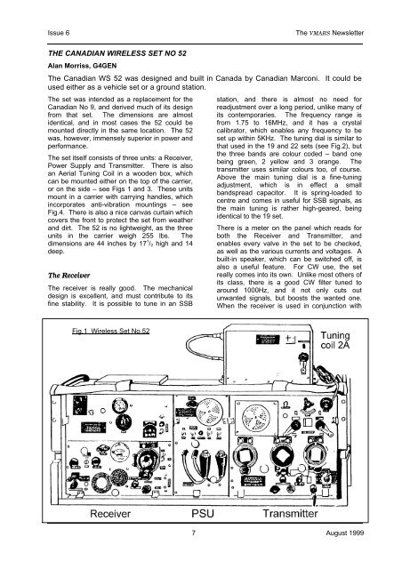
Issue 6<strong>The</strong> VMARS NewsletterTHE CANADIAN WIRELESS SET NO 52Alan Morriss, G4GEN<strong>The</strong> <strong>Canadian</strong> WS 52 was designed and built in Canada by <strong>Canadian</strong> Marconi. It could beused either as a vehicle set or a ground station.<strong>The</strong> set was intended as a replacement for the<strong>Canadian</strong> No 9, and derived much of its designfrom that set. <strong>The</strong> dimensions are almostidentical, and in most cases the 52 could bemounted directly in the same location. <strong>The</strong> 52was, however, immensely superior in power andperformance.<strong>The</strong> set itself consists of three units: a Receiver,Power Supply and Transmitter. <strong>The</strong>re is alsoan Aerial Tuning Coil in a wooden box, whichcan be mounted either on the top of the carrier,or on the side – see Figs 1 and 3. <strong>The</strong>se unitsmount in a carrier with carrying handles, whichincorporates anti-vibration mountings – seeFig.4. <strong>The</strong>re is also a nice canvas curtain whichcovers the front to protect the set from weatherand dirt. <strong>The</strong> 52 is no lightweight, as the threeunits in the carrier weigh 255 lbs. <strong>The</strong>dimensions are 44 inches by 17 1 / 2 high and 14deep.<strong>The</strong> Receiver<strong>The</strong> receiver is really good. <strong>The</strong> mechanicaldesign is excellent, and must contribute to itsfine stability. It is possible to tune in an SSBstation, and there is almost no need forreadjustment over a long period, unlike many ofits contemporaries. <strong>The</strong> frequency range isfrom 1.75 to 16MHz, and it has a crystalcalibrator, which enables any frequency to beset up within 5KHz. <strong>The</strong> tuning dial is similar tothat used in the 19 and 22 sets (see Fig.2), butthe three bands are colour coded – band onebeing green, 2 yellow and 3 orange. <strong>The</strong>transmitter uses similar colours too, of course.Above the main tuning dial is a fine-tuningadjustment, which is in effect a smallbandspread capacitor. It is spring-loaded tocentre and comes in useful for SSB signals, asthe main tuning is rather high-geared, beingidentical to the 19 set.<strong>The</strong>re is a meter on the panel which reads forboth the Receiver and Transmitter, andenables every valve in the set to be checked,as well as the various currents and voltages. Abuilt-in speaker, which can be switched off, isalso a useful feature. For CW use, the setreally comes into its own. Unlike most others ofits class, there is a good CW filter tuned toaround 1000Hz, and it not only cuts outunwanted signals, but boosts the wanted one.When the receiver is used in conjunction withFig.1 <strong>Wireless</strong> <strong>Set</strong> <strong>No.52</strong>7 August 1999
<strong>The</strong> VMARS Newsletter Issue 6the transmitter, the transmitter tank coil helps tomatch the aerial and definitely improves theperformance.<strong>The</strong> layout is fairly conventional for the period,with one RF and two IF stages (see the blockdiagram in Fig.5), but the first two IFtransformers are double tuned, and the couplingis increased by putting the selectivity switch toflat. <strong>The</strong>re are 13 valves used in it - all 12 volt,and mainly ARP3s. <strong>The</strong> IF frequency is420KHz, which must be borne in mind if anyattempt is made at realignment.As it is such a good receiver, large numbershave survived, and are fairly cheap as aconsequence. <strong>The</strong> main fault to which theyseem to be prone is the common one ofresistors going high or open circuit. It is worthchecking them all, as the set is easy to work on.<strong>The</strong> same goes for the capacitors. <strong>The</strong>sensitivity of the receiver is almost up topresent day standards, being in the region of0.7 microvolts for a 10 to 1 signal-to-noise ratioin CW, and 2.5 in R/T. It is also protected by agas discharge tube across the aerial input.<strong>The</strong> Transmitter<strong>The</strong> transmitter is also an excellent piece ofengineering, and gives little trouble. <strong>The</strong> layout(see Fig.6 for block diagram) consists of 6V6oscillator covering 1.75 to 4MHz with provisionfor two crystal positions. Next comes a 6V6Amplifier/Doubler followed by the 813 PA.<strong>The</strong>re is an additional 6V6 amplifier on band 3,dubbed the Intermediate Power Amplifier.<strong>The</strong>re is a voltage stabiliser for the oscillatorHT, which contributes to the nice note alwaysreported on CW.<strong>The</strong> PA is grid modulated on R/T by a 6V6 fedby another ARP3 speech amplifier. Negativefeedback is employed. On MCW the modulatoris used as the oscillator, and modulates thecarrier over 80%. <strong>The</strong> standard microphonedoes not seem to achieve more than 70%.Sidetone is fed tothe headphonesfrom themodulator, anddoes not comethrough thereceiver audio.<strong>The</strong> headset is thestandard type asused with the 19,22 and 62. On thepanel next to thekey socket is asimilar one, whichFig.2: <strong>The</strong> receiver tuning dial – an enhancementof that used on WS19, WS22, etctakes the standard <strong>Canadian</strong> C3 carbonmicrophone. This gives slightly greater depth ofmodulation, but does not sound so nice.A fan is fitted on the panel in a hinged door,which gives access to the interior of the set forvalve and crystal changing. It only operates athigh ambient temperatures. It is possible tochange all the valves and crystals through thisdoor, which has a micro switch to cut the HTwhen opened. However you have to besomewhat of a contortionist to do this – Isuppose practise must help.<strong>The</strong> tank circuit consists of two roller coasters,one for band 3 and the other for bands 1 and 2.<strong>The</strong> PA tuning capacitor is a massive affair,which looks as if it would handle more thandouble the power.<strong>The</strong> bottom row of controls consists of a metersensitivityswitch for the aerial current, afunction switch for the aerial current, a functionswitch with positions for R/T, MCW, CW andbreak in operation, and the meter selectionswitch. Between the function and meterswitches is the High/Low/Med power switch,Fig.3: WS52 showing the alternative arrangement of the tuning coilAugust 1999 8
Issue 6<strong>The</strong> VMARS Newsletterwhich has a lockto preventunauthorised useof high power.<strong>The</strong> power outputvaries from 45 to85 Watts in R/Tor 70 to 110 inCW in the HighPower position, tobetween 2 and 4Watts in Low.<strong>The</strong> current drainalso varies withthe power setting,being up to 57amps at 12 voltsin High PowerCW.<strong>The</strong> power supply<strong>The</strong> centre of the carrier is occupied by thePower Supply Unit. This contains the 1200 Voltdynamotor for the 813, a 300 volt one for therest of the transmitter, and a vibrator pack forthe receiver. On the panel of this are thevarious switches , and the two snatch plugs forthe headsets.<strong>The</strong> three units have plugs at the top rear,which connect to a bus which couples them –see Fig.4. <strong>The</strong> weakest part of the whole set isthe 1200 volt dynamotor. It always gavetrouble, and does not seem to be really up tothe job. Most of the British sets were convertedto use an external dynamotor, which seems agood idea.Nicht fur dummkopf!Fig.4: <strong>The</strong> carrier without the units fittedUnlike the 19 and similar sets, the 52 reallyrequires a skilled operator. It is “nicht furdummkopf”, as severe damage can be donequite quickly. <strong>The</strong> maximum PA current of 200milliamps can easily be exceeded on tune up ifthe correct procedure is not followed, or ifsufficient attention is not being paid. <strong>The</strong>modulation level seems to depend on the PAbeing correctly loaded, and doing stupid thingslike disabling the safety interlock could result ina lethal shock if contact is made with the 1200volt supply.Using the WS52 todayIf it is desired to operate the set today, the bestthing to do is to obtain the remains of a PowerSupply and build a mains one in the chassis.This is not a hard job, but there is not a lot ofroom, so some thought must be given to it. Inthe original one, the 813 filament only receivespower when the transmit relay is closed, but thisis not good for the valve, and it is much betterto have it on all the time the filament switch ison. This means that the fan supply must alsobe on, as the 813 generates a lot of heat.When the 52 is considered, it is hard to see whyit was so good. <strong>The</strong> same job could have beendone with something much simpler and cruder.<strong>The</strong> 1154 is an excellent illustration of thispoint. However, thank goodness it was built theway it was – the set is a delight to use once ithas been mastered. Sidetone is available tohelp CW sending, and good reports are the rule.<strong>The</strong> receiver gives good quality audio, andlistening to broadcast stations is a pleasure.<strong>The</strong> whole thing just works so well.One word of warning: the shank of the key isconnected to the bias, so in the key up state itcarries quite a voltage. Most keys have theshank connected to the case or base, and if theT/R switch is touched whilst holding the case,quite a shock is received. It is worthwhileobtaining the proper key.[See over for Figs 5 and 6 – Ed]~ ❁ ~9 August 1999
<strong>The</strong> VMARS Newsletter Issue 6August 1999 10
Issue 6<strong>The</strong> VMARS NewsletterFig.6: WS52 transmitter block diagram11 August 1999


