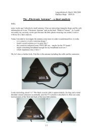
Heating of the hand-controller of the NexStar N5i/N8i ... - DD1US
Heating of the hand-controller of the NexStar N5i/N8i ... - DD1US
Heating of the hand-controller of the NexStar N5i/N8i ... - DD1US
- No tags were found...

You also want an ePaper? Increase the reach of your titles
YUMPU automatically turns print PDFs into web optimized ePapers that Google loves.
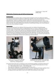
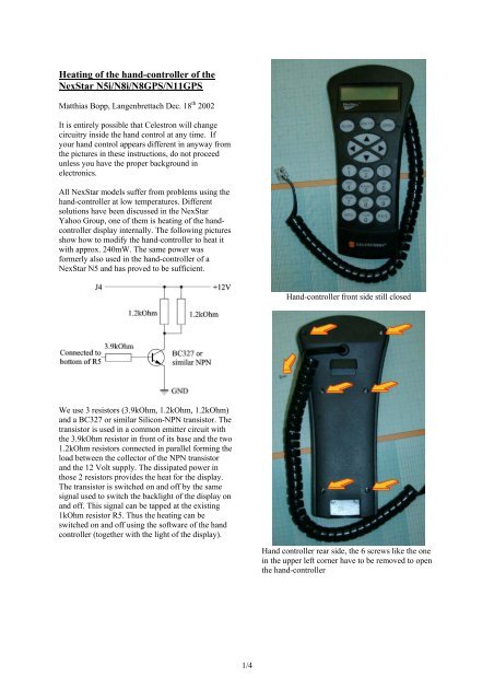
<strong>Heating</strong> <strong>of</strong> <strong>the</strong> <strong>hand</strong>-<strong>controller</strong> <strong>of</strong> <strong>the</strong><strong>NexStar</strong> <strong>N5i</strong>/<strong>N8i</strong>/N8GPS/N11GPSMatthias Bopp, Langenbrettach Dec. 18 th 2002It is entirely possible that Celestron will changecircuitry inside <strong>the</strong> <strong>hand</strong> control at any time. Ifyour <strong>hand</strong> control appears different in anyway from<strong>the</strong> pictures in <strong>the</strong>se instructions, do not proceedunless you have <strong>the</strong> proper background inelectronics.All <strong>NexStar</strong> models suffer from problems using <strong>the</strong><strong>hand</strong>-<strong>controller</strong> at low temperatures. Differentsolutions have been discussed in <strong>the</strong> <strong>NexStar</strong>Yahoo Group, one <strong>of</strong> <strong>the</strong>m is heating <strong>of</strong> <strong>the</strong> <strong>hand</strong><strong>controller</strong>display internally. The following picturesshow how to modify <strong>the</strong> <strong>hand</strong>-<strong>controller</strong> to heat itwith approx. 240mW. The same power wasformerly also used in <strong>the</strong> <strong>hand</strong>-<strong>controller</strong> <strong>of</strong> a<strong>NexStar</strong> N5 and has proved to be sufficient.Hand-<strong>controller</strong> front side still closedWe use 3 resistors (3.9kOhm, 1.2kOhm, 1.2kOhm)and a BC327 or similar Silicon-NPN transistor. Thetransistor is used in a common emitter circuit with<strong>the</strong> 3.9kOhm resistor in front <strong>of</strong> its base and <strong>the</strong> two1.2kOhm resistors connected in parallel forming <strong>the</strong>load between <strong>the</strong> collector <strong>of</strong> <strong>the</strong> NPN transistorand <strong>the</strong> 12 Volt supply. The dissipated power inthose 2 resistors provides <strong>the</strong> heat for <strong>the</strong> display.The transistor is switched on and <strong>of</strong>f by <strong>the</strong> samesignal used to switch <strong>the</strong> backlight <strong>of</strong> <strong>the</strong> display onand <strong>of</strong>f. This signal can be tapped at <strong>the</strong> existing1kOhm resistor R5. Thus <strong>the</strong> heating can beswitched on and <strong>of</strong>f using <strong>the</strong> s<strong>of</strong>tware <strong>of</strong> <strong>the</strong> <strong>hand</strong><strong>controller</strong> (toge<strong>the</strong>r with <strong>the</strong> light <strong>of</strong> <strong>the</strong> display).Hand <strong>controller</strong> rear side, <strong>the</strong> 6 screws like <strong>the</strong> onein <strong>the</strong> upper left corner have to be removed to open<strong>the</strong> <strong>hand</strong>-<strong>controller</strong>1/4
The display is still in <strong>the</strong> <strong>hand</strong>-<strong>controller</strong>, <strong>the</strong> flexcableis pulled out <strong>of</strong> its connector and <strong>the</strong> clampfor <strong>the</strong> backlight optical fibre cable is pulled <strong>of</strong>f <strong>the</strong>LED (marked by <strong>the</strong> 2 arrows). Next <strong>the</strong> 2 screwsfixing <strong>the</strong> black plastic holder for <strong>the</strong> display haveto be removed.Here <strong>the</strong> black plastic holder with <strong>the</strong> backlightoptical fibre cable is removed. The small blackrectangle marked with <strong>the</strong> arrow is a chip-on-glassdisplay <strong>controller</strong>.The 3.9kOhm SMD-resistor (marked with <strong>the</strong>arrow) is soldered to <strong>the</strong> lower pad <strong>of</strong> <strong>the</strong> 1kOhmresistor R5. The o<strong>the</strong>r side <strong>of</strong> <strong>the</strong> 3.9kOhm resistoris soldered to <strong>the</strong> base pin <strong>of</strong> <strong>the</strong> NPN transistor.The emitter <strong>of</strong> <strong>the</strong> NPN is soldered to ground,which is <strong>the</strong> lower right pin <strong>of</strong> transistor U10.Finally a wire (here yellow) is soldered to <strong>the</strong>collector <strong>of</strong> <strong>the</strong> NPN transistor. This wire goes to<strong>the</strong> resistors on <strong>the</strong> backside <strong>of</strong> <strong>the</strong> display. Ano<strong>the</strong>rwire is soldered to <strong>the</strong> pads J4 which is <strong>the</strong> +12Vsupply <strong>of</strong> <strong>the</strong> <strong>hand</strong>-<strong>controller</strong>. Also this wire goes to<strong>the</strong> resistors at <strong>the</strong> back <strong>of</strong> <strong>the</strong> display.This is <strong>the</strong> front side <strong>of</strong> <strong>the</strong> plastic holder showing<strong>the</strong> backlight optical fibre cable guiding <strong>the</strong> lightfrom <strong>the</strong> LED on <strong>the</strong> PCB to <strong>the</strong> LCD-displayNow <strong>the</strong> modification to <strong>the</strong> electronic <strong>of</strong> <strong>the</strong> PCBcan be done and <strong>the</strong> 2 resistors can be glued on <strong>the</strong>backside <strong>of</strong> <strong>the</strong> LCD-display (close to <strong>the</strong> display<strong>controller</strong>).The wires <strong>of</strong> <strong>the</strong> 2 resistors are isolated (purpleinsulation) to avoid a short circuit with <strong>the</strong> display<strong>controller</strong>.3/4
It is entirely possible that Celestron will changecircuitry inside <strong>the</strong> <strong>hand</strong> control at any time. Ifyour <strong>hand</strong> control appears different in any wayfrom <strong>the</strong> pictures in <strong>the</strong>se instructions, do notproceed unless you have <strong>the</strong> proper background inelectronics. I cannot give any guarantee for <strong>the</strong>modifications nor held responsible for any damage.Fur<strong>the</strong>r modifications including a simpler designwith permanent heating using only two 2 resistorscan be found on my webpage http://www.dd1us.deMany thanks to Mike Swanson, Dan Hupp andFrank Dilatush for reviewing <strong>the</strong>se instructions andgiving me helpful hints for improvements.Questions and comments are always welcome.Please send <strong>the</strong>m to dd1us@amsat.org.Kind regardsMatthiasThe resistors have been glued to <strong>the</strong> back <strong>of</strong> <strong>the</strong>display using “superglue” (Cyanacrylat) and <strong>the</strong>n<strong>the</strong> display and its holder have been reassembled.Also <strong>the</strong> connections <strong>of</strong> <strong>the</strong> flex-board and <strong>the</strong>optical fibre cable are reassembled.Modified <strong>hand</strong>-<strong>controller</strong> before back part <strong>of</strong> <strong>the</strong>casing is reattached4/4