M2150 2DC Installation Instructions - G4S Technology
M2150 2DC Installation Instructions - G4S Technology
M2150 2DC Installation Instructions - G4S Technology
- No tags were found...

You also want an ePaper? Increase the reach of your titles
YUMPU automatically turns print PDFs into web optimized ePapers that Google loves.
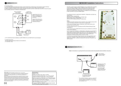
3Additional Information<strong>M2150</strong> <strong>2DC</strong> <strong>Installation</strong> <strong>Instructions</strong>UL Compliance Notes:1). For UL1076 Proprietary Burglar Alarm Systems and Non-Stand Alone UL294 Access Control System (central monitoringemployed) installations, Altronix AL400ULX power supply must be used for system battery supervision function.2). When using Altronix AL400ULX power supply, the installer will need to provide a remote input to the <strong>2DC</strong> to monitor AC powerloss and battery supervision conditions as indicated below:Altronix AL400ULXPower SupplyAC FailMonitoringRelayBatteryMonitoringRelay12 VDC Out+ -BlackRed4). Replacement Parts:Use only replacement parts provided by the manufacturer:F1, P/N R-0811-1000CNONCCNONCBlackBlack10K Ohm10K OhmI/O Board atDB/DBU Location+-+-MonitorPoint 17000-0126-+MonitorPoint 2CabinetAC Power /Tamper Board12 VDC to power Localboards & devicesProgram Monitor Point 1 as 3State N.C., and program theMonitor Point Message to read“AC Power Fail, (Add BoardDescription)”Program Monitor Point 2 as 3State N.C., and Alarm Messageshould read “Battery Trouble,(Add Board Description)”3). For UL294 Stand-Alone <strong>Installation</strong>s, the MN-TRANS-75-UL and MN-PSU-KIT can be employed.The <strong>2DC</strong> is used to expand an <strong>M2150</strong> database unit, by enabling direct connectionof two extra 20mA or Wiegand readers. Additional monitor points and auxiliaryoutputs are available by fitting an optional I/O Module (the module type useddetermines the number of available monitor points and auxiliary outputs). Anoptional Dual RS485 Reader Interface Module is available for non-UL installations,to allow connection for up to two RS485 readers.For additional information regarding the installation, configuration and proper useof this product:SMS User Guide, P/N 9600-0429<strong>M2150</strong> Access Control Design Guide, P/N 9600- 0420<strong>M2150</strong> Intrusion Guide, P/N 9600-0540.<strong>M2150</strong> UL1076 Compliance Manual, P/N 9600-0449.Notes:1). Consult local AHJ (Authority Having Jurisdiction) when installing access controlreaders and locking mechanisms to any portal in an egress path.2). The use of Fail Closed / secure configuration shall be determined by localbuilding codes and the local AHJ.3). Wiring methods shall be in accordance with NEC (National Electrical Code)ANSI/NFPA 70.4). This device must be installed within the secure area / perimeter for UL1076 andUL294 Listed installations.5). For Access Control Systems in a “Stand Alone” configuration only, the followingPower supplies are to be installed: Model MN-PSU-KIT with MN-TRANS-75-ULtransformer. Any additional power supply used (e.g. for door releases and auxiliaryoutputs) must be power limited, UL listed for Access Control Systems andAccessories. All interconnecting devices must be UL Listed.6). Some devices described in these instructions may not be applicable for sitesrequiring UL compliance. Please refer to the Access Control Design Guide fordetails of the controllers, modules and features that have been UL tested for usewith this device.1Mounting the Optional ModulesNote: For information on mounting the <strong>2DC</strong> into the cabinet, refer to the appropriate cabinet installation instructions.WIM-2 MODULE(required if Wiegandreaders are used)<strong>2DC</strong>9600-0466. <strong>M2150</strong> <strong>2DC</strong> <strong>Installation</strong> <strong>Instructions</strong>, Issue 1.3 11th July 2011.© <strong>G4S</strong> <strong>Technology</strong> 2011. <strong>G4S</strong> <strong>Technology</strong> Limited cannot be held liable for technical andeditorial omissions or errors made herein; nor for incidental or consequential damagesresulting from the furnishing, performance or use of this material. All trademarksacknowledged.NOTE: This equipment has been tested and found to comply with the limits for a Class Adigital device, pursuant to part 15 of the FCC Rules. These limits are designed to providereasonable protection against harmful interference when the equipment is operated in acommercial environment. This equipment generates, uses and can radiate radio frequencyenergy and, if not installed and used in accordance with the instructions, may cause harmfulinterference to radio communications. Operation of this equipment in a residential area islikely to cause harmful interference. In which case, the user will be required to correct theinterference at his own expense.SpecificationsReaders: 2 max.Reader port voltage range: 8.89 to 13.49Vdc.Quiescent supply input: 60mA @11.7 to 12.7Vdc (excludesreaders and optional modules, with no relays energized).Maximum supply input: 330mA @11.7 to 12.7Vdc (all modulesfitted, all board & module relays energized, excluding readers).Each relay consumes 20mA when energized.Operating Range: 14 to 131°F (-10 to 55°C) max. Humidity 15 to90% non-condensing; indoor use only.Compliance: EN50133, 1999/5/EC, UL 294 Access Control &UL1076 Proprietary Burglar Alarm Systems.OPTIONALI/O MODULEFor connection details, seethe appropriate I/O Module<strong>Installation</strong> <strong>Instructions</strong>For an AC8/4 I/O Module, inputs are numbered 1to 8, and outputs are numbered 1 to 4. For anOC4/8, inputs are numbered 1 to 4, and outputsare numbered 1 to 8.OPTIONAL DUAL RS485READER MODULE(NOT AVAILABLE FORUL INSTALLATIONS)For connection details,see the Dual RS485Reader Interface Module<strong>Installation</strong> <strong>Instructions</strong>
2<strong>2DC</strong> Connection Details450ft (150m) max with Belden 9503, or 900ft(300m) by doubling power cores with Belden 9504.+VRx-Rx+READER 1 (20mA/Wiegand)(500mA max)20mATx-Tx+0VTwisted pairsOR12VGreen LEDWiegandData 1Data 0Red LEDGroundCabinetCabinetTwo readers at one door - UseReader 1 for entry reader andReader 2 for exit reader.Connect door furniture to Door 1.12VGRN12V10RED0VTx-Tx+Rx-Rx+0V225ft (75m) max withBelden 9537, or 450ft(150m) by doubling powercores with Belden 9539.WiegandNote: reader portvoltage range is8.89 to 13.49Vdc.20mAExitRequestButton(optional)1500ft (500m) max; 24 AWGEXIT+DOOR-DOOR+EXIT-DoorMonitor1500ft (500m) max;. 24 AWGCabinetDOOR 1Bypassed Device(optional)(28Vdc, 3A max)CabinetNOBYPASSDoor Release(28Vdc, 3A max)Ensure release isnoise suppressedCNCNOCNCRELEASE0V+VPower Supply (seeAccess ControlDesign Guide)Connect to Normally Open(NO) or Normally Closed(NC), as appropriate.READER 2(20mA/Wiegand)DOOR 2Note: UL compliance requires power-limited and nonpower-limitedwiring to be separated by at least 0.25”(7mm). Please refer to the cabinet installation instructions.Note: UL compliance requires power-limited and nonpower-limitedwiring to be separated by at least 0.25”(7mm). Please refer to the cabinet installationinstructions.Note: The board contains an automatically-resettablefuse for each reader. If a fuse trips, you must removethe load completely before the fuse resets.Note: Consult the local Authority Having Jurisdiction(AHJ) when installing access control readers andlocking mechanisms to any portal in an egress path.Polarity unimportantConnect to ac input ofPower Supply Board(polarity unimportant)TAMPER SWITCHAND POWERINDICATOR-+Set reader switch to "C" for 20mAreader or "W" for WiegandTAMPERTAMPERAC MON+AC MON -Short tamperterminals if a tamperswitch is not used.- +Connect to AC MONITORterminal block on power supplyboard (if used). If this connectionis not made, a "Power Fail" alarmwill be generated at the PC eachtime the system re-starts.WARNING: Incorrect connections willpermanently damage the board.CWBit SwitchesAddress ADR0 ADR1 ADR21 0 (OFF) 0 (OFF) 0 (OFF)2 1 (ON) 0 (OFF) 0 (OFF)3 0 (OFF) 1 (ON) 0 (OFF)4 1 (ON) 1 (ON) 0 (OFF)5 0 (OFF) 0 (OFF) 1 (ON)6 1 (ON) 0 (OFF) 1 (ON)7 0 (OFF) 1 (ON) 1 (ON)8 1 (ON) 1 (ON) 1 (ON)Not usedADR2ADR1ADR0<strong>2DC</strong>ONSet the address of the <strong>2DC</strong> using the bit switches. Useone of the following addresses:When connected to a DBU: any unique address.When connected to a 2DBC: any address except 1.When connected to a 4DBC: any address except 1 and 2.When connected to an 8DBC: address 5, 6, 7 or 8.1 2 3 4FIT WIM-2 IF USINGWIEGAND READERSCOM-COM+0V12V+12Vdc0VPowersupply inputCabinet3000ft (1km) max; Belden 9502Use supplied cableCONNECTIONS TO DATABASE UNIT AND OTHEROPTIONAL REMOTE DOOR/ALARMS CONTROLLERSTwistedpairDatabase unitCOMMS+0VGround one end onlyMake sure the building ground isconnected to a ground stud in the cabinet.ControllerCOMMS-COMMS-COMMS+0V