Product Page Ultravac Pumps LV Series ...
Product Page Ultravac Pumps LV Series ...
Product Page Ultravac Pumps LV Series ...
- No tags were found...

Create successful ePaper yourself
Turn your PDF publications into a flip-book with our unique Google optimized e-Paper software.
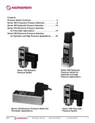
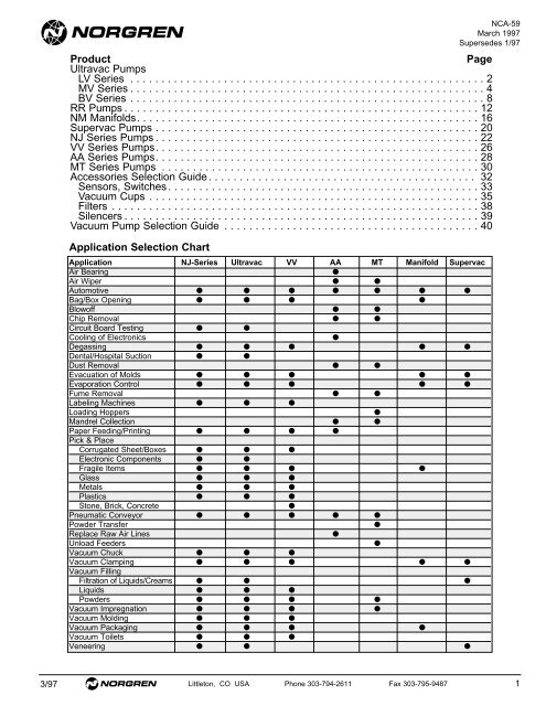
<strong>Product</strong><strong>Page</strong><strong>Ultravac</strong> <strong>Pumps</strong><strong>LV</strong> <strong>Series</strong> . . . . . . . . . . . . . . . . . . . . . . . . . . . . . . . . . . . . . . . . . . . . . . . . . . . . . . . . . 2MV <strong>Series</strong> . . . . . . . . . . . . . . . . . . . . . . . . . . . . . . . . . . . . . . . . . . . . . . . . . . . . . . . . . 4BV <strong>Series</strong> . . . . . . . . . . . . . . . . . . . . . . . . . . . . . . . . . . . . . . . . . . . . . . . . . . . . . . . . . 8RR <strong>Pumps</strong> . . . . . . . . . . . . . . . . . . . . . . . . . . . . . . . . . . . . . . . . . . . . . . . . . . . . . . . . . 12NM Manifolds. . . . . . . . . . . . . . . . . . . . . . . . . . . . . . . . . . . . . . . . . . . . . . . . . . . . . . . 16Supervac <strong>Pumps</strong> . . . . . . . . . . . . . . . . . . . . . . . . . . . . . . . . . . . . . . . . . . . . . . . . . . . . 20NJ <strong>Series</strong> <strong>Pumps</strong> . . . . . . . . . . . . . . . . . . . . . . . . . . . . . . . . . . . . . . . . . . . . . . . . . . . . 22VV <strong>Series</strong> <strong>Pumps</strong>. . . . . . . . . . . . . . . . . . . . . . . . . . . . . . . . . . . . . . . . . . . . . . . . . . . . 26AA <strong>Series</strong> <strong>Pumps</strong>. . . . . . . . . . . . . . . . . . . . . . . . . . . . . . . . . . . . . . . . . . . . . . . . . . . . 28MT <strong>Series</strong> <strong>Pumps</strong> . . . . . . . . . . . . . . . . . . . . . . . . . . . . . . . . . . . . . . . . . . . . . . . . . . . 30Accessories Selection Guide . . . . . . . . . . . . . . . . . . . . . . . . . . . . . . . . . . . . . . . . . . . 32Sensors, Switches . . . . . . . . . . . . . . . . . . . . . . . . . . . . . . . . . . . . . . . . . . . . . . . . . . 33Vacuum Cups . . . . . . . . . . . . . . . . . . . . . . . . . . . . . . . . . . . . . . . . . . . . . . . . . . . . . 35Filters . . . . . . . . . . . . . . . . . . . . . . . . . . . . . . . . . . . . . . . . . . . . . . . . . . . . . . . . . . . 38Silencers . . . . . . . . . . . . . . . . . . . . . . . . . . . . . . . . . . . . . . . . . . . . . . . . . . . . . . . . . 39Vacuum Pump Selection Guide . . . . . . . . . . . . . . . . . . . . . . . . . . . . . . . . . . . . . . . . . 40Application Selection ChartApplication NJ-<strong>Series</strong> <strong>Ultravac</strong> VV AA MT Manifold SupervacAir Bearing●Air Wiper ● ●Automotive ● ● ● ● ● ● ●Bag/Box Opening ● ● ● ●Blowoff ● ●Chip Removal ● ●Circuit Board Testing ● ●Cooling of Electronics●Degassing ● ● ● ● ●Dental/Hospital Suction ● ●Dust Removal ● ●Evacuation of Molds ● ● ● ● ●Evaporation Control ● ● ● ● ●Fume Removal ● ●Labeling Machines ● ● ●Loading Hoppers●Mandrel Collection ● ●Paper Feeding/Printing ● ● ● ●Pick & PlaceCorrugated Sheet/Boxes ● ● ●Electronic Components ● ●Fragile Items ● ● ● ●Glass ● ● ●Metals ● ● ●Plastics ● ● ●Stone, Brick, Concrete●Pneumatic Conveyor ● ● ● ● ●Powder Transfer●Replace Raw Air Lines●Unload Feeders●Vacuum Chuck ● ● ●Vacuum Clamping ● ● ● ● ●Vacuum FillingFiltration of Liquids/Creams ● ● ●Liquids ● ● ●Powders ● ● ● ●Vacuum Impregnation ● ● ● ●Vacuum Molding ● ● ●Vacuum Packaging ● ● ● ●Vacuum Toilets ● ● ●Veneering ● ● ●NCA-59March 1997Supersedes 1/973/97 Littleton, CO USA Phone 303-794-2611 Fax 303-795-9487 1
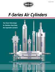
<strong>LV</strong> <strong>Series</strong> Vacuum <strong>Pumps</strong> - 60H<strong>LV</strong>160H, <strong>LV</strong>060H, <strong>LV</strong>2QR60H● Compact, lightweight configurations ideal forsmall part pick and place applications.● Fast evacuation of small vessels for purging● Require little installation space and can bepositioned close to the vacuum point for fastresponse.● Integral valve ensures high cycle rates, no delaydue to long plumbing lines.● Modular design eliminates plumbing betweencomponents and speeds installation.● Individual electrical connections for precisecontrol of vacuum creation and the duration ofblow-off.<strong>LV</strong>160H<strong>LV</strong>060HTechnical Data3 Way SV ValveValve Type: 3/2 Normally closed solenoid operated spring returnValve Body Material: Anodized aluminumSeal Material: BunaMedia: Filtered (50 micron), non-lubricated airOperating Pressure: 0-150 PSIOperating Temperature: 15°-140°FAverage Life: 100,000,000 cyclesPower Consumption:AC - 110 VAC, 50/60 Hz, 1 Watt (w/o LED)DC - 24 VDC, 2 Watt (w/LED)Response Time: 8ms open,15 ms closedCycle Rate: 2500 cycles per minuteElectrical Connection: DIN 40050Manual Override: Standard with pushbuttonVenturi SpecificationsMedium: Filtered (50 Micron), unlubricated airOperating Pressure: 80 PSIOperating Temperature: 15°-140°FOperating Noise Level: 68 dBAMaterial: Anodized aluminum, brass, and buna-NNORVAC venturi pumps are designed tooperate at peak efficiency at 80 PSI. Systemsrequiring operation at 60 PSI should beordered with the designate -60 at the end ofthe part number,i.e. <strong>LV</strong>0160H24VDC-60*Specify either 24vdc or 110vac when ordering.Ordering InformationChoose a body style based on features andaccessories. Venturi size is based on vacuumlevel and flow requirements. If required,indicate the valve operating voltage.Order using the following designates:Body style<strong>LV</strong>0<strong>LV</strong>1<strong>LV</strong>1QR*<strong>LV</strong>1 60H 24VDCValve Voltage:24 VDC110 VACVacuum Level:Medium - (20" Hg.)H-High - (28" Hg.)Venturi Flow Capacity:60*Quick Action Blow-off2 Littleton, CO USA Phone 303-794-2611 Fax 303-795-9487 3/97
<strong>LV</strong> <strong>Series</strong> Vacuum <strong>Pumps</strong> - 60HAll Dimensions in Inches (mm)Performance DataAir Consump. (SCFM)Vacuum Flow (scfm) vs. Vacuum Level ("Hg) @ 80 PSIModel @ 80 PSI0" 3" 6" 9" 12" 15" 18" 21" 24" 27" 28"0.50 0.38 0.32 0.30 0.27 0.23 0.20 0.13 0.05 0.02 0.0060H 0.80 Evacuation Time (seconds) for a 1 cu. ft. volume ("Hg)0.00 15.00 29.80 50.60 74.50 102.80 135.90 183.20 245.90 410.20 790.80<strong>LV</strong>060H1.312.40#10–32 AirSupply Port.87.47.63 Square.63(2) .120ø Mounting Holes#10–32 AirVacuum Port<strong>LV</strong>160H, <strong>LV</strong>1QRH#10–32 Air Vacuum Port0.84Blowoff Segmentfor <strong>LV</strong>1QR60H1.852.94Blowoff Segmentfor <strong>LV</strong>1QR60H2.50#10–32 AirSupply PortL.E.D.0.630.631.250.471.071.30.120ø Mounting HolesTyp 2 Pic3/97 Littleton, CO USA Phone 303-794-2611 Fax 303-795-9487 3
MV <strong>Series</strong> Vacuum <strong>Pumps</strong>60, 90, 100, 150● Modular components allow the designer tospecify only those features necessary for theirspecific application.● Interchangeable cartridge venturies increaseflexibility.● Eliminates plumbing between components forfaster installation.● MV6 Vacuum Pump comes with integral 6 waysolenoid valve and silencer as standard.● Integral 6 way valve energizes venturi rapidly forhigh cycle rates–no loss due to plumbing lines.● Optional air reservoir (P/N NQR10) can be addedfor even faster vacuum release (MV6-only).Technical Data6-Way MV Spool Valve6 Way Valve Type: 6/2 pilot operated solenoid valvew/ spring returnValve Body Material: Die cast zincSpool Material: Polished aluminumSeal Material: PolyethyleneMedia: Filtered (50 micron), non-lubricated airOperating Pressure: 45-150 PSIOperating Temperature: 15°-140°FAverage Life: 100,000,000 cyclesPower Consumption:AC - 110 VAC, 50/60 Hz, 1 Watt (w/o LED)DC - 24 VDC, 2 Watt (w/LED)Response Time: 11ms open, 22 ms closeCycle Rate: 2000 Cycles per minuteElectrical Connection: DIN 40050Manual Override: Standard with pushbuttonVenturi SpecificationsMedium: Compressed air or other gasesOperating Pressure: 80 PSIOperating Temperature: 15°-140°FOperating Noise Level: 72 dBAMaterial: Anodized Aluminum, Brass, and Buna-NPrinciples of OperationA transducer produces a vacuum by forcing compressed airthrough a limiting orifice into a venturi section. As the air exits theorifice it expands, increasing in velocity to supersonic speedsbefore entering the venturi section. This creates a vacuum ornegative pressure at the vacuum inlet port located between theorifice and venturi section. This high velocity insures efficient andeffective operation.CompressedAirVacuumExhaustOrdering InformationChoose a body style based on features andaccessories. Venturi size is based on vacuumlevel and flow requirements. If required,indicate the valve operating voltage.Order using the following designates:Body styleMV1MV2MV6*MV1MV2MV2 100 H 24VDC*MV6NC <strong>Series</strong>Valve Voltage:24 VDC110 VACVacuum Level:Medium - (20" Hg.)H-High - (28" Hg.)Venturi Flow Capacity:60, 90, 100, 150Select the venturi that best fits your applicationbased on the four performance characteristics:vacuum level, vacuum flow, evacuation speed,and air consumption (see facing page). Tosimplify selection, venturi performance hasbeen separated into two categories, “M” formedium and “H” for high vacuum applications.*24 VDC or 110 AC available on MV6NORVAC venturi pumps are designed tooperate at peak efficiency at 80 PSI. Systemsrequiring operation at 60 PSI should beordered with the designate -60 at the end ofthe part number, i.e. MV1100H604 Littleton, CO USA Phone 303-794-2611 Fax 303-795-9487 3/97
MV <strong>Series</strong> Vacuum <strong>Pumps</strong>All Dimensions in Inches (mm)Performance DataM <strong>Series</strong> Venturis Medium Vacuum ApplicationsThe “M” series for “Medium” vacuum levels of up to 20" Hg for applications involving porous materials (cardboard, wood, fabric, etc.)ModelAir ConsumptionVacuum Flow (scfm) vs. Vacuum Level ("Hg) @ 80 PSI(SCFM)@ 80 PSI 0" 3" 6" 9" 12" 15" 18" 20"60M 0.50 0.50 0.40 0.30 0.22 0.15 0.08 0.03 0.0090M 1.40 1.40 1.25 1.20 1.05 0.85 0.65 0.25 0.00100M 1.80 2.10 2.00 1.85 1.75 1.60 1.25 0.80 0.00150M 2.80 3.50 3.20 2.95 2.75 2.50 1.80 0.95 0.00ModelEvacuation Time (seconds) based on 1 cu. ft. volume ("Hg)0" 3" 6" 9" 12" 15" 18" 20"60M 0.00 12.50 25.10 43.90 68.60 99.30 153.70 227.0090M 0.00 3.75 7.20 12.40 19.10 29.90 52.00 104.00100M 0.00 2.65 5.80 9.90 16.20 22.90 36.20 56.60150M 0.00 1.35 3.20 5.20 7.70 11.80 23.40 52.00H <strong>Series</strong> Venturis High Vacuum ApplicationsThe “H” series for “High” vacuum levels of up to 28" Hg for applications involving non-porous materials (steel, plastic, glass, etc.)ModelAir ConsumptionVacuum Flow (scfm) vs. Vacuum Level ("Hg) @ 80 psi(SCFM)@ 80 PSI 0" 3" 6" 9" 12" 15" 18" 21" 24" 27" 28"60H 0.80 0.50 0.38 0.32 0.30 0.27 0.23 0.20 0.13 0.05 0.02 0.0090H 1.80 1.20 1.00 0.95 0.90 0.85 0.75 0.70 0.52 0.47 0.20 0.00100H 2.80 2.00 1.85 1.75 1.57 1.40 1.25 1.05 0.84 0.70 0.35 0.00150H 4.80 3.20 2.80 2.50 2.30 2.00 1.60 1.40 1.20 0.80 0.50 0.00ModelEvacuation Time (seconds) based on 1 cu. ft. volume ("Hg)0" 3" 6" 9" 12" 15" 18" 21" 24" 27" 28"60H 0.00 15.00 29.80 50.60 74.50 102.80 135.90 183.20 245.90 410.20 790.8090H 0.00 6.50 12.30 18.90 32.50 47.00 65.40 92.20 130.00 222.20 281.30100H 0.00 2.70 6.50 11.20 17.50 25.80 38.40 55.20 79.20 166.70 251.80150H 0.00 2.30 3.80 6.50 10.20 14.10 21.30 44.90 55.00 81.00 125.003/97 Littleton, CO USA Phone 303-794-2611 Fax 303-795-9487 5
MV <strong>Series</strong> Vacuum <strong>Pumps</strong> - 60, 90, 100, 150All Dimensions in Inches (mm)MV11/4" NPT AirSupply Port(2) .12 (3) ø Mounting Holes1.78(45).75 Sq.(19).58(15)3.20(81)4.58(116)1.10(28)1/8" NPT Vacuum PortMV2Optional Vacuum Sensor.75(19)1/8 NPTGauge Port#10–32 Sensor Port1.5(38).20(5)1.5(38)1/4" NPT AirSupply Port.44(11).23 (6)2.75(70)3.20(81)4.58(116)1.10(28)(2) .206 (5) ø Mtg. Holes1/4" NPTVacuum Port6 Littleton, CO USA Phone 303-794-2611 Fax 303-795-9487 3/97
MV <strong>Series</strong> Vacuum <strong>Pumps</strong> - 60, 90, 100, 150All Dimensions in Inches (mm)MV64.65(118) 1.59(40)1.50(38)L.E.D.AdditionalReleaseVolumeOptionalVacuumSensor.437(11)1.70(43)M.O.#10–32 AdditionalVolume Port#10–32Sensor Port.75(19) 1.50(38).20(5) .32(8)1/4" NPTAir SupplyPort2.75(70)3.80(97) 5.18(132)(2) .206 (5) ø Mounting HolesWeight - 14.8 oz.Exhaust Port - 1/4” NPTSilencer - NAA41.70(43)1/4" NPT Vacuum PortMV SERIES CARTRIDGE IDENTIFICATION CODENOZZLE DIFFUSER COLORNC60MNC60HNC90MNC90HNC100MNC100HNC150MNC150HNC90LNC100LNC150L6090100150BLUEGOLDBLACKGREY"L" <strong>Series</strong> Cartridge – 10"Hg."M" <strong>Series</strong> Cartridge – 20"Hg."H" <strong>Series</strong> Cartridge – 28"Hg.3/97 Littleton, CO USA Phone 303-794-2611 Fax 303-795-9487 7
BV <strong>Series</strong> Vacuum <strong>Pumps</strong>200, 250, 300, 350● The BV <strong>Series</strong> offers high vacuum flow rates forrapid evacuation of large volumes of air.● Ideal for vacuum filling operations.● BV8200 model will power multiple vacuum cupsand can handle large vacuum cups for heavy,porous objects.● BV8250 model can be used with systems havinglarge vacuum lines or rotary vacuum valves.● BV8- and BV9- models are available withoptional vacuum gauge (VG150).BV8 200MBV9 300MTechnical DataVenturi–Medium: Filtered (50 micron), unlubricated airOperating Pressure: 80 PSIOperating Temperature: 15°F-140°FOperating Noise level: 72 dBAMaterial: Anodized aluminumOrdering Information1. Body styles and venturi size have been combinedfor a total of 8 models.2. Order using the following part numbers:BV8 200MBV8 200HBV8 250MBV8 250HBV9 300MBV9 300HBV9 350MBV9 350HMechanical and solid state vacuum sensorsand switches can be factory installed uponrequest.NORVAC venturi vacuum pumps are designedto operate at peak efficiency at 80 PSI.Systems requiring operation at 60 PSI shouldbe ordered with the -60 at the end of the partnumber i.e., BV9350H60.8 Littleton, CO USA Phone 303-794-2611 Fax 303-795-9487 3/97
BV <strong>Series</strong> Vacuum <strong>Pumps</strong>Performance DataM <strong>Series</strong> Venturis Medium Vacuum ApplicationsThe “M” series for “Medium” vacuum levels of up to 20" Hg for applications involving porous materials (cardboard, wood, fabric, etc.) or where leakage is present.ModelAir ConsumptionVacuum Flow (scfm) vs. Vacuum Level ("Hg) @ 80 PSI(SCFM)@ 80 PSI 0" 3" 6" 9" 12" 15" 18" 20"200M 4.80 6.00 5.30 4.90 4.00 3.50 2.50 1.10 0.00250M 7.80 9.50 9.20 8.30 7.00 4.70 3.40 2.20 0.00300M 12.50 20.00 19.00 16.30 13.80 8.10 5.50 3.30 0.00350M 17.00 28.00 24.00 19.40 16.80 14.50 11.20 4.80 0.00ModelEvacuation Time (seconds) based on 1 cu. ft. Volume ("Hg)0" 3" 6" 9" 12" 15" 18" 20"200M 0.00 0.75 1.90 3.20 5.30 8.70 17.10 42.60250M 0.00 0.45 1.10 2.40 3.80 6.00 9.70 15.40300M 0.00 0.00 0.00 1.10 1.80 2.70 4.60 8.70350M 0.00 0.00 0.00 1.00 1.50 2.10 4.30 8.40H <strong>Series</strong> Venturis High Vacuum ApplicationsThe “H” series for “High” vacuum levels of up to 28" Hg for applications involving non-porous materials (steel, plastic, glass, etc.)ModelAir ConsumptionVacuum Flow (scfm) vs. Vacuum Level ("Hg) @ 80 PSI(SCFM)@ 80 PSI 0" 3" 6" 9" 12" 15" 18" 21" 24" 27" 28"200H 7.80 5.40 4.70 3.85 3.30 3.00 2.60 2.10 1.60 1.20 0.60 0.00250H 12.50 9.00 8.50 7.85 7.00 6.50 5.30 3.90 2.50 1.80 0.90 0.00300H 22.00 20.00 17.00 14.00 12.70 12.00 10.00 7.40 4.90 2.70 1.30 0.00350H 28.00 28.00 22.00 18.70 15.90 14.50 11.80 8.10 5.70 4.50 2.25 0.00ModelEvacuation Time (seconds) based on 1 cu. ft. Volume ("Hg)0" 3" 6" 9" 12" 15" 18" 21" 24" 27" 28"200H 0.00 1.20 2.10 3.40 5.20 7.70 11.50 20.00 33.50 62.60 98.10250H 0.00 0.75 1.30 2.20 3.50 5.60 9.10 17.40 30.10 56.00 76.00300H 0.00 0.00 0.80 1.20 2.00 2.80 3.90 5.90 11.10 32.70 60.00350H 0.00 0.00 0.00 1.20 1.90 2.30 3.40 5.30 8.80 26.00 44.003/97 Littleton, CO USA Phone 303-794-2611 Fax 303-795-9487 9
BV <strong>Series</strong> Vacuum <strong>Pumps</strong> - 200, 250, 300, 350All Dimensions in Inches (mm)BV8200M, H1/8" NPT Gauge Port.206 (5)ø Mtg. Holes (2)1.50(38)1/4" NPT AirSupply Port0.20(5)2.20(56)4.00(102)1.50(38)3/8" NPT Vacuum PortWeight - 9.4 oz.Exhaust Port - 3/8" NPTSilencer - NAA61.00(25)0.50(13)1.13(29)5.81(148)BV8250M, H1/8" NPT Gauge Port1/4" NPT Supply PortOptional ST–8B Silencer0.20(5)1.13(29)2.20 (56)3.70 (94)4.00 (102)4.80(122)Optional FA–51 Silencerw/ 90ø Apapter Option5.25(133)1.00(25)1.12(28)3/8" NPTVacuum Port7.00(178)1.25ø(32)1.50(38)Muffler (indicated bydashed linetype) canbe fitted to either ofthese 1/2" NPT ports.Optional adapter can berotated 180 o to changethe muffler's position.Weight - 24.3 oz.Exhaust Port - 1/2" NPTSilencer - NFA511210 Littleton, CO USA Phone 303-794-2611 Fax 303-795-9487 3/97
BV <strong>Series</strong> Vacuum <strong>Pumps</strong> - 200, 250, 300, 350All Dimensions in Inches (mm)BV91/8" NPT Gauge Port3/8" NPT Supply PortOptional ST–8B Silencer3.50 (89) 1.50(38)6.00 (152)0.206ø (5) Mounting HolesTyp 2 Pic7.25 (184)4.80(122)Optional FA–51 Silencerw/ 90ø Apapter Option1.25ø(32)1.00(25)1.13(29)1/2" NPTVacuum Port7.00(178)Muffler (indicated bydashed linetype) canbe fitted to either ofthese 1/2" NPT ports.Optional adapter can berotated 180 o to changethe muffler's position.Weight - 24.3 oz.Exhaust Port - 1/2" NPTSilencer - NFA51123/97 Littleton, CO USA Phone 303-794-2611 Fax 303-795-9487 11
Rapid Response Blow Off Vacuum <strong>Pumps</strong>MVORR60H, MVIRR, MV2RR, BV8RR● Ideally suited for pick and place applicationsthat require accurate part placement and rapidpart release.● No external plumbing or on-site assembly isrequired.● Extremely fast part release.● Accurate part positioning.● One converter installation.● Automatically cleans vacuum lines.● Adjustable blow-off rate option available.BV8RR 200M<strong>LV</strong>0RR60HMV2RR90HTechnical DataOperating Pressure range: 20 to 120 psi Optimum 80 psiOperating Temperature range: 32° to 125°F (0° to 52°C)Cycle rates: Up to 300/min.Positive Release Pressure: 0 psiResponse Time: InstantaneousOrientation: Any PositionDuration: Based on System DesignValve disc material: vinylReplacement valve discs –<strong>Series</strong> <strong>LV</strong>: 10004<strong>Series</strong> MV: 10014NORVAC venturi pumps are designed to operate at peakefficiency at 80 PSI. Systems requiring operation at 60 PSI shouldbe ordered with the designate -60 at end of the part number, i.e.MVIRR100M60Ordering Information<strong>LV</strong>0RR-Available in the 60H Venturi size only.To order, use part number <strong>LV</strong>ORR60H,MV1RR-, MV2RR-, from 60-150 “M” or “H”.Choose any one of the 8 Venturi's listed in thebelow charts.i.e. BV1RR 90H, BV8RR-choose 200M or HBody Style<strong>LV</strong>0RRMV1RRMV2RRBV8RR**200 “M” or “H”MV1RR 60 HVacuum Level:H - HighM - MediumVacuum Flow Capacity60, 90, 100, 15012 Littleton, CO USA Phone 303-794-2611 Fax 303-795-9487 3/97
Rapid Response Blow Off Vacuum <strong>Pumps</strong>Performance data M <strong>Series</strong> Venturis Medium Vacuum ApplicationsThe “M” series for “Medium” vacuum levels of up to 20" Hg for applications involving porous materials (cardboard, wood, fabric, etc.)Air ConsumptionVacuum Flow (scfm) vs. Vacuum Level ("Hg) @ 80 PSIModel(SCFM)@ 80 PSI 0" 3" 6" 9" 12" 15" 18" 20"60M 0.50 0.50 0.40 0.30 0.22 0.15 0.08 0.03 0.0090M 1.40 1.40 1.25 1.20 1.05 0.85 0.65 0.25 0.00100M 1.80 2.10 2.00 1.85 1.75 1.60 1.25 0.80 0.00150M 2.80 3.50 3.20 2.95 2.75 2.50 1.80 0.95 0.00200M 4.80 6.00 5.30 4.90 4.00 3.50 2.50 1.10 0.00Evacuation Time (seconds) based on 1 cu. ft. Volume ("Hg)Model0" 3" 6" 9" 12" 15" 18" 20"60M 0.00 12.50 25.10 43.90 68.60 99.30 153.70 227.0090M 0.00 3.75 7.20 12.40 19.10 29.90 52.00 104.00100M 0.00 2.65 5.80 9.90 16.20 22.90 36.20 56.60150M 0.00 1.35 3.20 5.20 7.70 11.80 23.40 52.00200M 0.00 0.75 1.90 3.20 5.30 8.70 17.10 42.60Performance Data H <strong>Series</strong> Venturis High Vacuum ApplicationsThe “H” series for “High” vacuum levels of up to 28" Hg for applications involving non-porous materials (steel, plastic, glass, etc.)Air ConsumptionVacuum Flow (scfm) vs. Vacuum Level ("Hg) @ 80 PSIModel(SCFM)@ 80 PSI 0" 3" 6" 9" 12" 15" 18" 21" 24" 27" 28"60H 0.80 0.50 0.38 0.32 0.30 0.27 0.23 0.20 0.13 0.05 0.02 0.0090H 1.80 1.20 1.00 0.95 0.90 0.85 0.75 0.70 0.52 0.47 0.20 0.00100H 2.80 2.00 1.85 1.75 1.57 1.40 1.25 1.05 0.84 0.70 0.35 0.00150H 4.80 3.20 2.80 2.50 2.30 2.00 1.60 1.40 1.20 0.80 0.50 0.00200H 7.80 5.40 4.70 3.85 3.30 3.00 2.60 2.10 1.60 1.20 0.60 0.00Evacuation Time (seconds) based on 1 cu. ft. Volume ("Hg)Model0" 3" 6" 9" 12" 15" 18" 21" 24" 27" 28"60H 0.00 15.00 29.80 50.60 74.50 102.80 135.90 183.20 245.90 410.20 790.8090H 0.00 6.50 12.30 18.90 32.50 47.00 65.40 92.20 130.00 222.20 281.30100H 0.00 2.70 6.50 11.20 17.50 25.80 38.40 55.20 79.20 166.70 251.80150H 0.00 2.30 3.80 6.50 10.20 14.10 21.30 44.90 55.00 81.00 125.00200H 0.00 1.20 2.10 3.40 5.20 7.70 11.50 20.00 35.50 62.60 98.103/97 Littleton, CO USA Phone 303-794-2611 Fax 303-795-9487 13
Rapid Response Blow Off VacuumAll Dimensions in Inches (mm)MV0RR60H#10-32Supply Port(2) .120ø (3)Mounting Holes1.58 (40)0.45(11)0.63(16)0.90 (23)1.14 (29)1.69 (43)0.67(17)#10-32Vacuum Port0.31(8)3.23(82)MV1RR2.05 (52)(2) 0.120 (3)øMounting Holes0.58(15)0.75(19)1/4" NPTSupply Port.08(2)1.10(28)1.78 (45)3.20 (81)4.58 (116)0.37(9)1/8" NPT Vacuum Port14 Littleton, CO USA Phone 303-794-2611 Fax 303-795-9487 3/97
Rapid Response Blow Off Vacuum <strong>Pumps</strong>All Dimensions in Inches (mm)MV2RR#10–32SensorPort2.80 (71)1.50 (38)0.20(5)0.75(19)0.23(6)2.75 (70)(2) 0.206 (5)øMounting Holes3.20 (81)1/4" NPTSupply Port1.10 (28)0.38(10)4.58 (116)1/4" NPTVacuum PortBV8RR0.75(19)2.83 (72)1.00(25)1/4" NPT Air Inlet1.13 (29)2.20 (56) 1.50 (38)Optional Sensor Mounting0.20(5)0.206 (5)ø Typ 2 Pic1/2" NPT ExhaustOptional Right AngleSilencer Adapter3/97 Littleton, CO USA Phone 303-794-2611 Fax 303-795-9487 15
NM <strong>Series</strong> Segmented Manifolds60, 90, 100, 150● NM <strong>Series</strong> segmented manifolds offer maximumapplication versatility where multiple vacuumstations are required.● Modular components enable the designer toselect from 8 interchangeable cartridges andspecify only the features necessary for theirspecific application.● Any of the 60M through 150H cartridges can beused in any of the vacuum stations.● Precision blow-off control and rapid recovery.(1) NM5 (5) B52NM# (Indicates NORVAC Manifold and number of stations)Pump OptionsVenturi cartridgeSizes and layoutA=60M E=100MB=60H F=100HC=90M G=150MD=90H H=150HA 2 1Ordering ExampleThe following ordering example details theinformation needed to order a NORVACmanifold consisting of 3 stations.Valve voltage and layout1 = 12VDC 2 = 24VDCVacuum switch/sensorConfiguration and layout0= no device1=VSXP - sourcing switch2=VSXN - sinking switch3=VSXL - logic switch4=VSSA - 4-20mA sensor5=VSSV - 0-5VDC sensor(See pp. 33-34)Ordering Information1. Use specifications chart on following page toselect venturi(s) based on vacuum level,vacuum flow, evacuation speed, and airconsumption.2. Select vacuum switch/sensor configurationand layout on the left.3. Select valve voltage and layout on the left..5(13).5(13)One NM3 NORVAC manifold consisting of:Pos. Qty. PN. Desc.1 1 C32 90M log. sw.24 VDC2 1 D32 90H, log.sw.,24 VDC3 1 G22 150M, sink sw., 24 VDCNotes: Each segment must have appropriate sizeand cartridge designation.Up to 20 segments available in an NM..75 (19) per segment4.25 (108)4.75 (121)Vacu1/8"Manifold segments numbered left to right16 Littleton, CO USA Phone 303-794-2611 Fax 303-795-9487 3/97
NM <strong>Series</strong> Segmented Manifolds - 60, 90, 100, 150Performance DataM <strong>Series</strong> Venturis Medium Vacuum ApplicationsThe “M” series for “Medium” vacuum levels of up to 20" Hg for applications involving porous materials (cardboard, wood, fabric, etc.)ModelAir ConsumptionVacuum Flow (scfm) vs. Vacuum Level ("Hg) @ 80 PSI(SCFM)@ 80 PSI 0" 3" 6" 9" 12" 15" 18" 20"60M 0.50 0.50 0.40 0.30 0.22 0.15 0.08 0.03 0.0090M 1.40 1.40 1.25 1.20 1.05 0.85 0.65 0.25 0.00100M 1.80 2.10 2.00 1.85 1.75 1.60 1.25 0.80 0.00150M 2.80 3.50 3.20 2.95 2.75 2.50 1.80 0.95 0.00ModelEvacuation Time (seconds) based on 1 cu. ft. volume ("Hg)0" 3" 6" 9" 12" 15" 18" 20"60M 0.00 12.50 25.10 43.90 68.60 99.30 153.70 227.0090M 0.00 3.75 7.20 12.40 19.10 29.90 52.00 104.00100M 0.00 2.65 5.80 9.90 16.20 22.90 36.20 56.60150M 0.00 1.35 3.20 5.20 7.70 11.80 23.40 52.003/97 Littleton, CO USA Phone 303-794-2611 Fax 303-795-9487 17
NM <strong>Series</strong> Segmented Manifolds - 60, 90, 100, 150Performance DataH <strong>Series</strong> VENTURIS High Vacuum ApplicationsThe “H” series for “High” vacuum levels of up to 28" Hg for applications involving non-porous materials (steel, plastic, glass, etc.)ModelAir ConsumptionVacuum Flow (scfm) vs. Vacuum level ("Hg) @ 80 psi(SCFM)@ 80 PSI 0" 3" 6" 9" 12" 15" 18" 21" 24" 27" 28"60H 0.80 0.50 0.38 0.32 0.30 0.27 0.23 0.20 0.13 0.05 0.02 0.0090H 1.80 1.20 1.00 0.95 0.90 0.85 0.75 0.70 0.52 0.47 0.20 0.00100H 2.80 2.00 1.85 1.75 1.57 1.40 1.25 1.05 0.84 0.70 0.35 0.00150H 4.80 3.20 2.80 2.50 2.30 2.00 1.60 1.40 1.20 0.80 0.50 0.00ModelEvacuation Time (seconds) based on 1 cu. ft. volume ("Hg)0" 3" 6" 9" 12" 15" 18" 21" 24" 27" 28"60H 0.00 15.00 29.80 50.60 74.50 102.80 135.90 183.20 245.90 410.20 790.8090H 0.00 6.50 12.30 18.90 32.50 47.00 65.40 92.20 130.00 222.20 281.30100H 0.00 2.70 6.50 11.20 17.50 25.80 38.40 55.20 79.20 166.70 251.80150H 0.00 2.30 3.80 6.50 10.20 14.10 21.30 44.90 55.00 81.00 125.0018 Littleton, CO USA Phone 303-794-2611 Fax 303-795-9487 3/97
NM <strong>Series</strong> Segmented Manifolds - 60, 90, 100, 150All Dimensions in Inches (mm)Manifold.5(13).5(13).75 (19) per segment4.25 (108)Vacuum Port1/8" NPT4.75 (121)Manifold segments numbered left to right3.016 (77)1.00(25)1.75 (44)4.25 (108)1/4'' NPT air inlet - both ends0.26 (7)ø Mounting holes (typ 4)3/97 Littleton, CO USA Phone 303-794-2611 Fax 303-795-9487 19
Supervac <strong>Series</strong> Vacuum <strong>Pumps</strong>● Highvac vacuum pumps achieve vacuum levelsup to 29.5"Hg.● Ideal for vessel evacuation, process control andHVAC applications.● Cartridge assembly has no moving parts makingit easy to clean.● High vacuum rates, compact size, and designfeatures allow the use of smaller, less costlycomponents and reduces maintenance repaircosts.● Suited for applications where contaminants arepresent.SV3SV2SV1Technical DataVacuum Level: The magnitude of suction created by the vacuumpump. Vacuum level is affected by elevation and barometricpressure.Note: For each 1000 feet of elevation, vacuum decreases byapproximately 1" Hg.Performance DataModelAir ConsumptionVacuum Flow (scfm) v. Vacuum Level ("Hg) @ 80 PSI(SCFM)@ 80 PSI 0" 4" 8" 12" 16" 20" 24" 28" 29.5"SV1 4.90 3.20 2.80 2.50 2.10 1.60 1.50 1.00 0.50 0.00SV2 8.60 5.00 3.90 3.40 2.90 2.20 1.60 1.10 0.65 0.00SV3 22.00 16.00 12.20 10.20 9.00 7.80 5.30 2.70 0.90 0.0020 Littleton, CO USA Phone 303-794-2611 Fax 303-795-9487 3/97
Supervac <strong>Series</strong> Vacuum <strong>Pumps</strong>All Dimensions in Inches (mm)SupervacKBJHL NPTExhaust PortShown WithSilencerAEDFMCGIModelDimensionsA B C D E F G H I J K L M SilencerAir Supply Vacuum Exhaust MTGPort Port Port Hole ØSV1 .38 (10) 2.25 (57) 4.58 (116) 3.20 (81) 1.78 (45) * .08 (2) 1.50 (38) .75 (19) 1/4 NPT 1/8 NPT 1/4 NPT .125 AA4SV2 .758 (19) 4.00 (102) 7.56 (192) 4.00 (102) 2.20 (56) 1.50 (38) .20 (5) 2.80 (71) 1.00 (25) 1/4 NPT 1/4 NPT 1/2 NPT .206 ST8ASV3 .758 (19) 4.00 (102) 9.80 (249) 5.00 (127) 2.50 (64) 1.50 (38) .20 (5) 2.75 (70) 1.00 (25) 3/8 NPT 1/4 NPT 1/2 NPT .206 ST8B3/97 Littleton, CO USA Phone 303-794-2611 Fax 303-795-9487 21
NJ <strong>Series</strong> Vacuum <strong>Pumps</strong>● 16 standard models with a full range of optionalaccessories for pick and place applications.● NJ <strong>Series</strong> pumps operate with instantaneousresponse in pulsed applications or on acontinuous basis.● Rugged, cylindrical design.● Maintenance free pumps have no moving partsor seals that require replacement.● Manufactured from anodized aluminum.● Stainless steel, PVC, and other materials areavailable for high temperature and/or causticapplications.NJM 350NJM 200NJM 60MOrdering InformationSelect a NJ <strong>Series</strong> pump with the lowest airconsumption that meets the applicationrequirements based on the following criteria:Vacuum Level, Vacuum Flow, VacuumForce and Cycle Times.Standard operating supply pressure for the NJ<strong>Series</strong> is 80psi. Specify 60psi supply power ifrequired by adding -60psi after model number.Specify pump model: i.e. NJS250Specify accessories and vacuum cup.The use of NORVAC silencers is stronglyrecommended. They will reduce noise level upto 30 dB without back pressure.NJ <strong>Series</strong> can also be powered by alternatemedias. Consult factory.22 Littleton, CO USA Phone 303-794-2611 Fax 303-795-9487 3/97
NJ <strong>Series</strong> Vacuum <strong>Pumps</strong>Performance DataNJM series for “Medium” vacuum levels of up to 20" Hg for applications involving porous materials (cardboard, wood, fabric, etc.)ModelAir ConsumptionVacuum Flow (scfm) vs. Vacuum Level ("Hg) @ 80 psi(SCFM)@ 80 PSI 0" 3" 6" 9" 12" 15" 18" 20"NJM 60M* 0.50 0.50 0.40 0.30 0.22 0.15 0.08 0.03 0.00NJM 90M 1.40 1.40 1.25 1.20 1.05 0.85 0.65 0.25 0.00NJM 100M 1.80 2.10 2.00 1.85 1.75 1.60 1.25 0.80 0.00NJM 150M 2.80 3.50 3.20 2.95 2.75 2.50 1.80 0.95 0.00NJM 200 4.80 6.00 5.30 4.90 4.00 3.50 2.50 1.10 0.00NJM 250 7.80 9.50 9.20 8.30 7.00 4.70 3.40 2.20 0.00NJM 300 12.50 20.00 19.00 16.30 13.80 8.10 5.50 3.30 0.00NJM 350 17.00 28.00 24.00 19.40 16.80 14.50 11.20 4.80 0.00* The “M” suffix denotes miniature.Performance DataModelEvacuation Time based on 1 cu. ft. volume ("Hg)0" 3" 6" 9" 12" 15" 18" 20"NJM 60M 0.00 12.50 25.10 43.90 68.60 99.30 153.70 227.00NJM 90M 0.00 3.75 7.20 12.40 19.10 29.90 52.00 104.00NJM 100M 0.00 2.65 5.80 9.90 16.20 22.90 36.20 56.60NJM 150M 0.00 1.35 3.20 5.20 7.70 11.80 23.40 52.00NJM 200 0.00 0.75 1.90 3.20 5.30 8.70 17.10 42.60NJM 250 0.00 0.45 1.10 2.40 3.80 6.00 9.70 15.40NJM 300 0.00 0.00 0.00 1.10 1.80 2.70 4.60 8.70NJM 350 0.00 0.00 0.00 1.00 1.50 2.10 4.30 8.403/97 Littleton, CO USA Phone 303-794-2611 Fax 303-795-9487 23
NJ <strong>Series</strong> Vacuum <strong>Pumps</strong>Performance DataNJH series for “High” vacuum levels of up to 28" Hg for applications involving non-porous materials (steel, plastic, glass, etc.)ModelAir ConsumptionVacuum Flow (scfm) vs. Vacuum Level ("Hg) @ 80 psi(SCFM)@ 80 PSI 0" 3" 6" 9" 12" 15" 18" 21" 24" 27" 28"NJH 60M* 0.80 0.50 0.38 0.32 0.30 0.27 0.23 0.20 0.13 0.05 0.02 0.00NJH 90M 1.80 1.20 1.00 0.95 0.90 0.85 0.75 0.70 0.52 0.47 0.20 0.00NJH 100M 2.80 2.00 1.85 1.75 1.57 1.40 1.25 1.05 0.84 0.70 0.35 0.00NJH 150M 4.80 3.20 2.80 2.50 2.30 2.00 1.60 1.40 1.20 0.80 0.50 0.00NJH 200 7.80 5.40 4.70 3.85 3.30 3.00 2.60 2.10 1.60 1.20 0.60 0.00NJH 250 12.50 9.00 8.50 7.85 7.00 6.50 5.30 3.90 2.50 1.80 0.90 0.00NJH 300 22.00 20.00 17.00 14.00 12.70 12.00 10.00 7.40 4.90 2.70 1.30 0.00NJH 350 28.00 28.00 22.00 18.70 15.90 14.50 11.80 8.10 5.70 4.50 2.25 0.00* The “M” suffix denotes miniature.Performance DataModelEvacuation Time (seconds) based on 1 cu. ft. volume ("Hg)0" 3" 6" 9" 12" 15" 18" 21" 24" 27" 28"NJH 60M 0.00 15.00 29.80 50.60 74.50 102.80 135.90 183.20 245.90 410.20 790.80NJH 90M 0.00 6.50 12.30 18.90 32.50 47.00 65.40 92.20 130.00 222.20 281.30NJH 100M 0.00 2.70 6.50 11.20 17.50 25.80 38.40 55.20 79.20 166.70 251.80NJH 150M 0.00 2.30 3.80 6.50 10.20 14.10 21.30 44.90 55.00 81.00 125.00NJH 200 0.00 1.20 2.10 3.40 5.20 7.70 11.50 20.00 33.50 62.60 98.10NJH 250 0.00 0.75 1.30 2.20 3.50 5.60 9.10 17.40 30.10 56.00 76.00NJH 300 0.00 0.00 0.80 1.20 2.00 2.80 3.90 5.90 11.10 32.70 60.00NJH 350 0.00 0.00 0.00 1.20 1.90 2.30 3.40 5.30 8.80 26.00 44.0024 Littleton, CO USA Phone 303-794-2611 Fax 303-795-9487 3/97
NJ <strong>Series</strong> Vacuum <strong>Pumps</strong>All Dimensions in Inches (mm) (mm)NJ <strong>Series</strong>E vacuumportBAF(exhaust port)Dsupply portCModelDimensionsA B C D E F Recommended LengthNPT NPT NPT Silencer* w/Silencer60MNAA4 4.13 (105)0.75 (19) 2.75 (70) 0.75 (19) 1/8 1/8 1/490M NST4 4.13 (105)100MNAA4 4.13 (105)0.75 (19) 2.75 (70) 0.75 (19) 1/8 1/8 1/4150M NST4 4.88 (124)150 1.25 (32) 4.0 (102) 1.0 (25) 1/4 3/8 3/8NAA6 5.88 (149)NST6A 8.0 (203)NAA6 5.88 (149)200 1.25 (32) 4.0 (102) 1.0 (25) 1/4 3/8 3/8 NST6A 8.0 (203)NFA51-3/8 9.75 (248)250 1.25 (32) 4.0 (102) 1.0 (25) 1/4 3/8 3/8NFA51-3/8 9.75 (248)NST6B 8.0 (203)300 1.25 (32) 5.0 (127) 1.0 (25) 3/8 3/8 3/8NFA51-3/8 10.75 (273)NST6B 10.25 (260)350 1.50 (38) 6.0 (152) 1.50 (38) 1/2 1/2 1/2NFA51-1/2 11.75 (298)NST8B 11.25 (286)*Note: For ultra quiet operation the STAA4 Silencer can be used on all of the M series models. All M series w/STAA4 length = 6.00".3/97 Littleton, CO USA Phone 303-794-2611 Fax 303-795-9487 25
VV <strong>Series</strong>Variable Flow Vacuum <strong>Pumps</strong>● Vacuum flow rates of up to 120 SCFM, andvacuum levels of up to 25" Hg.● Non-clogging, straight-through design.● High performance to air consumption ratio.● Field adjustable for your specific application.● Can be used to pick and place concrete block,or packaging materials that are coated with finepowder.● Commonly used in industrial air driven vacuumcleaners to remove liquid/solid mixtures fromsump areas.VV 500VV 200Principles of OperationThe variable performance of the VV pump is achieved byincreasing the annular gap between the venturi nozzle and thediffuser. Rotating the diffuser section counter-clockwise willincrease the opening, allowing more compressed air to flowthrough the unit and increasing both the vacuum flow and thevacuum level. The result is a variable vacuum pump that can beadjusted to meet an application’s exact requirements.Performance DataModelAir Consumption vs. Vacuum Level ("Hg) @ 80 PSINumber0" 5" 10" 15" 20" 25"VV 100 0 .70 1.20 1.30 2.10 2.60VV 150 0 1.30 1.70 2.40 3.20 4.50VV 200 0 2.40 3.70 4.70 6.00 6.80VV 250 0 4.00 6.00 8.30 9.70 12.00VV 375 0 6.20 11.50 17.00 21.00 29.00VV 500 0 12.00 22.00 28.00 33.00 45.00VV 750 0 23.00 30.80 44.00 63.00 90.00RecommendedSilencerST4ST4ST4ST4AST8BST12CST16CMax AirVacuum ConsumptionFlow SCFM* SCFM*2.60 1.303.20 1.506.00 3.0010.00 6.0030.00 13.0060.00 25.00120.00 40.00* These values can be achieved at 15"Hg.26 Littleton, CO USA Phone 303-794-2611 Fax 303-795-9487 3/97
VV <strong>Series</strong> Variable Flow Vacuum <strong>Pumps</strong>All Dimensions in Inches (mm)VV <strong>Series</strong>SpecificationsDimensionsModel A B C D E F G H I Silencer SilencerBarrel Collar Input Barrel Collar Thread LengthID Length (NPTF) OD OD ID NPTFVV 100 0.10 (25) 1.50 (38) 1.50 (38) 0.75 (19) 1/8 .75 (19) 1.25 (32) 0.88 (22) 1/4 NST4 2.50VV 150 0.15 (4) 1.50 (38) 1.50 (38) 0.75 (19) 1/8 .75 (19) 1.25 (32) 0.88 (22) 1/4 NST4 2.50VV 200 0.20 (5) 1.50 (38) 1.50 (38) 0.75 (19) 1/8 .75 (19) 1.25 (32) 0.88 (22) 1/4 NST4 2.50VV 250 0.25 (6) 1.50 (38) 1.50 (38) 0.75 (19) 1/8 .75 (19) 1.25 (32) 0.88 (22) 1/4 NST4A 4.00VV 375 0.38 (10) 2.75 (70) 1.75 (44) 0.88 (22) 3/8 1.0 (25) 1.50 (38) 1.50 (38) 1/2 NST8B 5.20VV 500 0.50 (13) 2.50 (64) 2.0 (51) 1.0 (25) 3/8 1.25 (32) 2.0 (51) 1.50 (38) 3/4 NST12C 7.50VV 750 0.75 (19) 3.38 (86) 2.0 (51) 1.0 (25) 1/2 1.50 (38) 2.25 (57) 1.50 (38) 1 NST16C 7.503/97 Littleton, CO USA Phone 303-794-2611 Fax 303-795-9487 27
AA <strong>Series</strong> Vacuum <strong>Pumps</strong>For Air Amplification● High, 40:1 amplification ratios.● Can be used for applications requiring extremelyhigh levels of vacuum flow to rapidly evacuatelarge areas.● The unique design of the AA pump makes it anefficient and cost effective alternative to electricblowers or large volumes of raw compressed air.● 7 standard models are available with bores of1/8" to 2".● Air velocity and flow of all models are fieldadjustable to provide a wide range of conditionsto meet individual application requirements.AA 750AA 500Principles of OperationAA pumps operate on the “Coanda Effect” where a small volumeof compressed air is converted into a large flow of ambient air.Compressed air is emitted from an annular gap and passes over acurved surface into the throat of the unit. As the air passes overthis curved surface, similar to an air foil, a low pressure area iscreated inducing ambient air to flow into the throat with thecompressed air.Performance DataModel I.D. **Input Output VelocityNo. inches scfm scfm ft/sec3 12 2347AA 100* 0.13 (3) 2 8 15651 6 11733 18 860AA 200* 0.25 (6) 2 14 6851 10 4909 75 910AA 500H† 0.50 (13) 5 42 5303 22 2659 110 565AA 750H† 0.75 (19) 5 70 4203 40 1959 145 435AA 1000H† 1.0 (25) 5 95 2903 57 1749 240 314AA 1500H 1.50 (38) 5 150 1983 86 1239 350 269AA 2000H 2.0 (51) 5 220 1683 140 106Jam nut used to secure adjustment* 1/4" NPT male exhaust available** Data is at 80 PSI† See page 29 for optional threaded exhaust attachmentsTypical ApplicationsBlow drying, fume evacuation, cooling andimproved utilization of compressed air.28 Littleton, CO USA Phone 303-794-2611 Fax 303-795-9487 3/97
AA <strong>Series</strong> Vacuum <strong>Pumps</strong>All Dimensions in Inches (mm)AA <strong>Series</strong>A-I.D.Hose barbED*F*DFSupply Port (H)VacuumExhaustC B C*Vacuum (J)NPT Thread1.82 G Jam NutOptional Threaded Exhaust Attachments forModels AA 500H, 750H 1000Threaded C* D* F*Exhaust Model†Part No.NT 100 AA 500H 1" NPT 4.63 (118) 2.00 (51)NT 107 AA 750H 1" NPT 5.13 (130) 2.50 (64)NT 125 AA 1000H 1-1/2" NPT 4.63 (130) 2.00 (51)DimensionsModelI.D. (NPTF) (NPTF)A B C D E F G H JAA 100 0.13 (3) 1.25 (32) 0.56 (14) 2.0 (51) 1.0 (25) 0.75 (19) 0.13 (3) 1/8 —AA 200 0.25 (6) 1.25 (32) 0.56 (14) 2.0 (51) 1.0 (25) 0.75 (19) 0.13 (3) 1/8 —AA 500H† 0.50 (13) 1.50 (38) 1.0 (25) 4.13 (105) 2.63 (67) 1.50 (38) 0.2 (5) 1/4 1/2AA 750H† 0.75 (19) 2.0 (51) 1.25 (32) 4.13 (105) 2.63 (67) 1.50 (38) 0.2 (5) 1/4 1AA 1000H† 1.0 (25) 2.25 (57) 1.50 (38) 4.13 (105) 2.63 (67) 1.50 (38) 0.2 (5) 1/4 1-1/4AA 1500H 1.50 (38) 2.75 (70) 2.0 (51) 4.13 (105) 2.63 (67) 1.50 (38) 0.2 (5) 3/8 2AA 2000H 2.0 (51) 3.25 (83) 2.50 (64) 4.13 (105) 2.63 (67) 1.50 (38) 0.2 (5) 3/8 2-1/2Jam nut is used to secure adjustment† See above chart for optional threaded attachment.3/97 Littleton, CO USA Phone 303-794-2611 Fax 303-795-9487 29
MT <strong>Series</strong> High Flow Vacuum <strong>Pumps</strong>For Material Transfer● MT <strong>Series</strong> provides a reliable and cost effectivemethod of in-line transfer of complex shapesand bulk materials.● Creates instantaneous vacuum flow and high airvelocity.● Straight through, smooth bore design.● Compact design facilitates placement close tothe work area for maximum efficiency and easeof installation.● MT pumps are available in 15 standard modelswith inside diameters from 1/8" to 3".● Modified and custom engineered units available.MT 76MT 56MT 23Principles of OperationCompressed air is fed into an exterior annular ring that has anumber of orifices leading into the main tube of a transducer. Asthe compressed air exits from the orifices, its velocity increases tosupersonic speed. The air forced into the center of the tuberotates with a twisting motion similar to a worm screw. Thiscyclonic flow creates a powerful vacuum capable of drawingmaterials into, and through the transducer.As a vacuum source, the MT series are capable of rapidevacuation of a large volume of air to a low vacuum level.VacuumExhaustOrdering InformationSelect an MT pump based on the following:Inside diameterVacuum flowVacuum forceAir ConsumptionContact factory for custom pumpsTypical ApplicationsUnloading vibrator feedersReloading hoppers with plastic regrindTransferring of engine valves in grinding operationChip removal in drilling operationTransfer power detergent and caustic chemicalsConvey peanut husksSalvage removal in trimming operationMandrel collection systemCompressedAir30 Littleton, CO USA Phone 303-794-2611 Fax 303-795-9487 3/97
Performance DataMT <strong>Series</strong> High Flow Vacuum <strong>Pumps</strong>All Dimensions in Inches (mm)Model I.D. Air Vacuum Vacuum Air ConsumptionNo. Velocity Flow Level @ 40 psi @80 psi(ft/sec) (scfm) (" Hg)MT 13 0.13 (3) 585 3 8 1.1 2MT 23 0.25 (6) 490 10 8 3.1 6MT 33 0.38 (10) 328 15 6 3.5 6MT 36 0.38 (10) 393 18 8 5.8 10MT 53 0.50 (13) 306 25 3 5.2 9MT 56 0.50 (13) 362 30 10 14 24MT 73 0.75 (14) 272 50 4.3 14 24MT 76 0.75 (14) 326 60 8 28 48MT 103 1.0 (25) 229 75 3 14 24MT 106 1.0 (25) 290 95 5.8 28 48MT 153 1.50 (38) 224 165 1.3 14 24MT 156 1.50 (38) 272 200 2.5 28 48MT 203 2.0 (51) 183 240 0.8 14 24MT 206 2.0 (51) 229 300 1.5 28 48MT 306 3.0 (76) 168 375 .7 32 60Values for velocity, vacuum flow, and vacuum level are for 80 psi input pressureDE F GBExhaustCA vacuumHI supply portDimensionsModelI.D.(NPTF)A B C D E F G H IMT 13 0.13 (3) 1.25 (32) 0.75 (19) 3.50 (89) 0.75 (19) 1.0 (25) 1.75 (44) 0.5 (13) 1/8MT 23 0.25 (6) 1.25 (32) 0.75 (19) 3.50 (89) 0.75 (19) 1.0 (25) 1.75 (44) 0.5 (13) 1/8MT 33 0.38 (10) 1.25 (32) 0.75 (19) 3.50 (89) 0.75 (19) 1.0 (25) 1.75 (44) 0.5 (13) 1/8MT 36 0.38 (10) 1.25 (32) 0.75 (19) 3.50 (89) 0.75 (19) 1.0 (25) 1.75 (44) 0.5 (13) 1/8MT 53 0.50 (13) 1.50 (38) 1.0 (25) 5.50 (140) 1.0 (25) 1.25 (32) 3.25 (83) 0.63 (16) 1/4MT 56 0.50 (13) 1.50 (38) 1.0 (25) 5.50 (140) 1.0 (25) 1.25 (32) 3.25 (83) 0.63 (16) 1/4MT 73 0.75 (19) 2.0 (51) 1.25 (32) 7.50 (191) 1.50 (38) 2.0 (51) 4.0 (102) 1.0 (25) 3/8MT 76 0.75 (19) 2.0 (51) 1.25 (32) 7.50 (191) 1.50 (38) 2.0 (51) 4.0 (102) 1.0 (25) 3/8MT 103 1.00 (25) 2.25 (57) 1.50 (38) 7.50 (191) 1.50 (38) 2.0 (51) 4.0 (102) 1.0 (25) 3/8MT 106 1.00 (25) 2.25 (57) 1.50 (38) 7.50 (191) 1.50 (38) 2.0 (51) 4.0 (102) 1.0 (25) 3/8MT 153 1.50 (38) 2.75 (70) 2.0 (51) 7.50 (191) 1.50 (38) 2.0 (51) 4.0 (102) 1.0 (25) 3/8MT 156 1.50 (38) 2.75 (70) 2.0 (51) 7.50 (191) 1.50 (38) 2.0 (51) 4.0 (102) 1.0 (25) 3/8MT 203 2.00 (51) 3.25 (83) 2.50 (64) 7.50 (191) 1.50 (38) 2.0 (51) 4.0 (102) 1.0 (25) 3/8MT 206 2.00 (51) 3.25 (83) 2.50 (64) 7.50 (191) 1.50 (38) 2.0 (51) 4.0 (102) 1.0 (25) 3/8MT 306 3.00 (76) 4.25 (108) 3.50 (89) 10.50 (267) 2.0 (51) 3.0 (76) 5.50 (140) 1.50 (38) 3/8These products will operate with as little as 3 psi.3/97 Littleton, CO USA Phone 303-794-2611 Fax 303-795-9487 31
Accessory Selection GuideAccessory Selection Guide<strong>Product</strong> Vacuum Filter Gauge Sensor Silencer Silencer Solenoid Switch Switch SensorCups AA ST Valve (Mech) Solid SolidState State<strong>LV</strong> <strong>Series</strong> ● ● ● ● ● ● ● ● ● ●MV <strong>Series</strong> ● ● ● ● ● ● ● ● ● ●BV <strong>Series</strong> ● ● ● ● ● ● ● ●RR ● ● ● ● ● ● ● ● ●Supervac ● ● ● ●NJ <strong>Series</strong> ● ● ● ● ● ● 1 1 1VV <strong>Series</strong> ● ●1 Remote applications only32Littleton, CO USA Phone 303-794-2611 Fax 303-795-9487 3/97
AccessoriesAdjustable Vacuum SwitchesNG 150● Ideal for use in automated systems to generate alow current electrical signal for input to a PLCor other logic controller.● Usually open, diaphragm operated● Utilize low-stressing deflecting contacts insteadof sliding or pivoting parts.● High reliability and long lifeNS W5ALX 4LX 4, LX 5To reduce plumbing and ease installation, thevacuum sensors may be fastened directly tothe MV 2, MV 3 and the MV 6 series ofvacuum pumps.LX 4SB, LX 5SBFor remote mounting, choose the LX 4SB orLX5SB subbase mounted versions.NS 4, NS 5Adjustable vacuum sensors.SpecificationsNS W5ANema 6 enclosure (IP67)Adjustable, 4" to 28" Hg.Electrical connection– DIN 46350AUL and CSA approvedCompact, sealed vacuum switch for automation and processcontrol applications. Especially suited for hazardous applicationsincluding wash down and dust laden air.Switch is field adjustable between 4" and 28"Hg. Adjusting screwis easily accessed below the DIN connector. Wiring can be eitherNormally Open or Normally Closed.Vacuum GaugeNG 150The NG 150 is a 0-30" Hg. vacuum with a 1-1/2" face and an 1/8”NPTM bottom mount connection.Part No Size Range Hysteresis/ Input Max. Output Operating Port Indi- Electrical(inches) Deadband Voltage Current Temp. cator ConnectionMECHANICAL SWITCHESNS 4 1x1x3/8 w/ 2-14.8"Hg. 1/2 % max 500 VAC/ 10-20 mA Sourcing -40°-250°F n/a None 12" flying leads3/8x3/16∅barb value 24 VDCNS 5 1x1x3/8 w/ 7.4-30"Hg. 1/2 % max 500 VAC/ 10-20 mA Sourcing -40°-250°F n/a None 12" flying leads3/8x3/16∅barb value 24 VDCLX 4 1x1.5x.75 thk 2-14.8"Hg. 1/2 % max 500 VAC/ 10-20 mA Sourcing -40°-250°F Optional Sub None 12" flying leadsvalue 24 VDC Base w/10-32LX 5 1x1.5x.75 thk 7.4-30"Hg. 1/2 % max 500 VAC/ 10-20 mA Sourcing -40°-250°F Optional Sub None 12" flying leadsvalue 24 VDC Base w/10-32NS W5A 1.84x4.26 4-28"Hg. ~ 20% 125-250 VAC 5 amp Sourcing -40°-176°F 1/8" NPTM None DIN 43650A12 VDC 7 amp N/O or N/C24 VDC 5 amp3/97 Littleton, CO USA Phone 303-794-2611 Fax 303-795-9487 33
AccessoriesSolid State Switches and Sensors● Ultra miniature electronic vacuum and pressuresensing and switching devices utilize the latestelectronic technology available.● Provide precision control for feedbackmechanisms or system monitoring● Can be incorporated directly onto NORVAC’sFastvac vacuum pumps.● Available for manifold applications wheremultiple sensing points for vacuum or pressureare required.● For applications requiring feedback for batch orprocess control, the sensors are available as a0-5Vdc or 4-20mA volt transducer device.● Vacuum or pressure setpoints, and hysteresisare adjustable on all switches.NS XPOrdering Information0.184 (5)0.50 (13)Note 1: All solid state devices, soldindividually, are mounted to a 1/8" thick basewith a #10-32 female port. Optional male portadapters are available in 10-32 and 1/8" NPT.Note 2: All solid state devices, soldindividually, can be optionally mounted to a3/8" thick remote mounting base with a #10-32port. Adapters are not available.Solid State Option Suffix:32N#10-32 Adapter18N1/8" NPTM AdapterRMNRemote Mount Base.187(5).375(10).783(20).750(19)#10–32 PortSolid StateSensor / Switch1.50 (38)1.281 (33)0.968 (25)0.50 (13)1.00 (25)24" Long3 Conductor LeadSpecificationsPart No Size Range Hysteresis/ Input Max. Output Operating Port Indi- Electrical(inches) Deadband Voltage Current Temp. cator ConnectionSOLID STATE SWITCHESNS XP 1x.75x.41 thk 0.5-30" Hg. ~ 0-15% 24 VDC 100mA Sourcing -40°-250°F See notes 1&2 LED 3 conductor/24"NS XN 1x.75x.41 thk 0.5-30" Hg. ~ 0-15% 24 VDC 100mA Sinking -40°-250°F See notes 1&2 LED 3 conductor/24"NS XL 1x.75x.41 thk 0.5-30" Hg. ~ 0-15% 24 VDC 100mA Sinking -40°-250°F See notes 1&2 LED 3 conductor/24"w/pullupresistorRS XP 1x.75x.41 thk 0-150 psi ~ 0-15% 24 VDC 100mA Sourcing -40°-250°F See notes 1&2 LED 3 conductor/24"RS XN 1x.75x.41 thk 0-150 psi ~ 0-15% 24 VDC 100mA Sinking -40°-250°F See notes 1&2 LED 3 conductor/24"RS XL 1x.75x.41 thk 0-150 psi ~ 0-15% 24 VDC 100mA Sinking -40°-250°F See notes 1&2 LED 3 conductor/24"w/pullupresistorSOLID STATE SENSORSNS SA 1x.75x.41 thk 0.5-30" Hg. n/a 24 VDC n/a 4-20mA -40°-250°F See notes 1&2 n/a 2 conductor/24"NS SV 1x.75x.41 thk 0.5-30" Hg. n/a 24 VDC n/a 0-5 VDC -40°-250°F See notes 1&2 n/a 3 conductor/24"RS SA 1x.75x.41 thk 0-150 psi n/a 24 VDC n/a 4-20mA -40°-250°F See notes 1&2 n/a 2 conductor/24"RS SV 1x.75x.41 thk 0-150 psi n/a 24 VDC n/a 0-5 VDC -40°-250°F See notes 1&2 n/a 3 conductor/24"34 Littleton, CO USA Phone 303-794-2611 Fax 303-795-9487 3/97
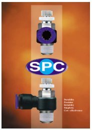
NORVAC Vacuum CupsStandard, Cleated, Bellows, andOval vacuum cupsNC 106● Norgren NORVAC vacuum cups are available infour designs: standard, cleated, bellows,and oval.● Available in vinyl, silicon, or polyurethane.● Four mounting methods are available: flange,snap on or bolt, push on or clamp, and bellowsmount.NC 27NC 32CNC 83Equation for calculating vacuum liftingforce using vacuum cups:Note: To covert ("Hg) vacuum level into PSIdivide by 2.Vacuum Force (lbs.) x Safety Factor =Vacuum Level (PSI) x Surface Area (in. 2 )SpecificationsVinyl (excellent wear resistance): 32° to 125°F (0° to 50°C)Silicon (good wear resistance, FDA approved): -50° to 400°F(-45 to 200°C)Polyurethane (chemically resistant): 32° to 125°F (0° to 50°C)AFlange StyleBSnap on or boltMounting StylesCPush on or clampDBellows mountStandard Vacuum CupStandard cups are flexible and work well inapplications that do not require lifting heavyloads. In food packaging for example, astandard cup can be used to apply a label toan uneven surface such as a package ofchicken.Standard Vacuum Cup SpecificationsStandard Model No. Effective Cup Area (in 2 ) A (O.D.) B C D E StyleNC 1 .01 .200 .225 .045 .225 .057 ANC 165A .05 .37 .25 .25 .37 .22 BNC 25 .02 .61 .62 .10 .50 .19 BNC 10 .30 1.00 .50 .28 .62 1/8 NPTF BNC 11 .40 1.19 .50 .28 .75 1/4 NPTF BNC 12 .60 1.44 .50 .50 .75 1/4 NPTF BNC 8 .44 1.50 .56 .38 .62 .23 BNC 37A .50 1.56 .81 .50 .87 1/4 NPTF BNC 168 .70 2.00 .69 .50 1.12 1/4 NPTF BNC 106 .80 2.50 .81 .50 1.12 1/4 NPTF BNC 30 1.10 3.09 1.44 .62 1.12 1/4 NPTF C3/97 Littleton, CO USA Phone 303-794-2611 Fax 303-795-9487 35DEACB
Accessories- Vacuum CupsAll Dimensions in Inches (mm)Cleated CupCleated cups have a rigid, low profile, and aredesigned to lift heavy loads. These cups perform wellwhen gripping smooth, flat heavy objects such assheet steel, glass (television picture tubes), andcoated corrugated.HE1DECBCLEATSACleated Vacuum Cup SpecificationsCleated Model No. Effective Cup Area (in 2 ) A (O.D.) B C D E StyleNC 36B .30 1.00 .36 .25 .56 .25 ANC 2E .37 1.37 1.06 .31 .62 .38 CNC 59 1.30 2.00 .62 .25 1.56 1/4 NPTF BNC 49 2.10 2.44 1.94 .81 1.04 1/4 NPTF CNC 27A 2.40 3.25 1.06 .44 2.25 1/4 NPTF BNC 27 3.40 4.25 1.00 .50 3.00 1/4 NPTF BNC 63 5.60 4.75 1.18 1.00 1.62 3/8 NPTF BNC 34 10.40 6.25 1.18 .81 5.00 3/8 NPTF BAll dimensions shown in inchesBellows Cup– with 1, 2, 3, or 4 convolutionsBellows cups have a pliable outer rim that will conform tocurved or uneven surfaces while the bellows sectionscompensate for inconsistent stack heights. Undervacuum, the accordion-style bellows cup will collapse oncontact. The collapsing action simulates a short cylinderstroke lifting the product for a short distance, possiblysaving the need for a separate lifting mechanism.E1DIECBBellows Vacuum Cup SpecificationsABellows Model No. Effective Cup Area (in 2 ) A (O.D.) B C D E StyleNCB 6 .01 .25 .43 .15 .15 .06 D-1NCB 105 .04 .42 .62 .21 .32 .15 D-1NCB 3 .05 .50 .56 .38 .31 .15 D-1NCB 15 .07 .62 .81 .40 .35 .14 D-1NCB 2 .11 .75 .68 .50 .51 .25 D-1NCB 20P .15 .87 .75 .50 .57 .20 D-1NC 33A5 .16 .75 1.00 .75 .69 .44 D-3NC 33A3 .20 .90 1.02 .62 .69 .44 D-2NCB 1 .25 1.20 .85 .77 .56 1/8 NPTF D-1NC 33A2 .25 1.27 1.00 .87 .69 1/4 NPTF D-2NC 33A .40 1.37 1.50 1.00 .65 1/4 NPTF D-3NC 32C .78 2.00 1.68 .81 .75 1/4 NPTF D-1NC 32 6.70 3.5 x 5.0 1.75 1.25 2.0x3.5 3/8 NPTF D-1NC 124 .24 1.00 1.37 .62 .62 .37 D-1NC 32D 1.00 2.00 1.86 1.12 .75 1/4 NPTF D-2NC 32B 2.00 2.75 2.00 1.28 1.00 1/4 NPTF D-1NC 130 4.90 3.31 2.38 2.18 2.38 3/4 NPTF D-4All dimensions shown in inchesMany other cup sizesavailable on request.36 Littleton, CO USA Phone 303-794-2611 Fax 303-795-9487 3/97
Accessories- Vacuum CupsAll Dimensions in Inches (mm)D-2Oval CupECBLike cleated cups, oval cups have heavy load handling capacitydue to their rigid design and large vacuum work area. Oval cupshave the largest lifting force because they provide the most surfacearea for a given cup footprint.A-2D-1A-1Oval Vacuum Cup SpecificationsOval Model No. Effective Cup Area (in 2 ) A1 x A2 B C D1 x D2 E StyleNC 89 1.75 1.12 x 2.75 .87 .70 .78 1/4 NPTF BNC 83 4.50 1.56 x 4.09 .94 .50 1.1 5x 3.6 1/4 NPTF BNC 87BL .44 1.70 x 1.50 .50 .20 .62 1/8 NPTF ANC 183 6.00 2.0 x 6.0 1.00 .39 1.25 x 5.2 1/4 (2 Ports) BNC 90 12.00 3.0 x 8.0 1.12 .53 2.12 x 7.1 3/8 (2 Ports) BUltraminiature Vacuum Cup SpecificationsUltraminiature Model No. Effective Cup Area (in 2 ) A (O.D.) B C D E OptionsNCVI 062 .003 .063 .126 .006 .055 .025 B/ESD/VNCVI 125 .02 .125 .120 .020 .070 .030 B/ESD/R/U/VNCVI 250 .05 .250 .200 .040 .100 .045 B/ESD/R/U/VNCVI 375 .11 .375 .250 .070 .130 .060 B/ESD/R/U/VNCVI 500 .19 .500 .300 .110 .160 .060 B/ESD/R/U/VNCVI 625 .30 .625 .310 .110 .160 .060 B/ESD/R/U/VNCVI 750 .44 .750 .320 .130 .160 .060 B/ESD/R/U/VOptionsB = Non-Marking Static Dissipative. Temperature range: -4°F to 248°F (-20°C to 120°C)ESD = ESD Safe High Temperature. Temperature range: -67°F to 446°F (-55°C to 250°C)R = Red Silicone High Temperature. Temperature range: -67°F to 482°F (-55°C to 350°C)U = Blue Silicon High Temperature. Temperature range: -67°F to 482°F (-55°C to 350°C)V = Probe (cup holders) available.Many other cup sizesavailable on request.3/97 Littleton, CO USA Phone 303-794-2611 Fax 303-795-9487 37
Accessories- In-line Vacuum FiltersAll Dimensions in Inches (mm)Compact in-line filters for adverse conditions provide the added protection of 10 micron filtration and have a 150 psipressure rating. Filters are constructed from rugged injection molded nylon and plastic. NORVAC offers eight differentdesign configurations for maximum placement versatility and easy installation.BBAACDCDNF125LPM (1.9 OZ)NF250LPM (2 OZ)NF375LPM (2 OZ)NF500F (5.6 OZ)NF750F (5.6 OZ)NF1000F (7.8 OZ)SpecificationsPart Number Description Ports A B C D Replacement ElementNF 125LPM 1/8" Male Low Profile 1/8"NPTMNF 250LPM 1/4" Male Low Profile 1/4"NPTM 2.4 3.1 2.0 1.9 NE1NF 375LPM 3/8" Male Low Profile 3/8"NPTMNF 250F 1/4" Female Filter 1/4"NPTF 3.7 3.0 3.25 1.9N3 75F 3/8" Female Filter 3/8"NPTF 3.7 3.0 3.25 1.9NE1LNF 500F 1/2" Female Filter 1/2"NPTF 5.35 3.6 4.8 2.95NF 750F 3/4" Female Filter 3/4"NPTF 5.35 3.6 4.8 2.95NE2NF 1000F 1" Female Filter 1"NPTF 6.35 5.0 5.6 4.1 NE3NORVAC’s unique single stage vacuum pumps do not require filters for maximum operating efficiency. Filters arerecommended for use in only the most adverse operating conditions to provide additional, in-line protection and usersatisfaction.38 Littleton, CO USA Phone 303-794-2611 Fax 303-795-9487 3/97
Accessories - SilencersAll Dimensions in Inches (mm)NORVAC silencers are extremely effective in reducing air exhaust noise from venturi pumps and other pneumatic devices.The NAA, NST, and NFA51 <strong>Series</strong> reduce noise levels by up to 30 dB while allowing high flow rates with minimal backpressure.NAA <strong>Series</strong> NFA51 <strong>Series</strong> NST <strong>Series</strong>The NAA <strong>Series</strong> silencers are compact,lightweight and have excellent noisereduction characteristics with minimalresistance to air flow. NAA <strong>Series</strong>silencers are almost one third smallerthan comparable products providingconsiderable space savings. The largesurface of the felt element resistscontamination far more than othermaterials such as sintered bronze,steel mesh, or porous polyethylene.The NFA51 <strong>Series</strong> silencers offerremarkable noise reduction for highvolume exhaust applications withoutcausing back pressure. Silencers areideal for quieting large air valves thatmust exhaust quickly to maintain highcycle rates. NORVAC uses theNFA51 silencers on their high flowventuri vacuum pumps where evensmall amount of back pressure woulddecrease performance.The NST-<strong>Series</strong>’ straight-throughdesign eliminates clogging byallowing contaminants to passdirectly through the silencer. Eachsilencer is tuned in proportion to itsexhaust flow to minimize noise andreduce frequency vibration. As airpasses through the silencer, noise isabsorbed by the dense felt liner. Thisreduces high pitch exhaust noise to agentle, low frequency flow of air.DANPT Threads (C)SpecificationsBØA threaded connection provides easyinstallation for replacement element,P/N RF513 1/4"1/4" NPT3/8" NPT1/2" NPT5 3/4"Even in the most adverse conditions,contaminants pass through thesilencer making the NST- <strong>Series</strong>ideal for silencing venturi pumps thatare continuously ingesting dirt anddebris.Dimensions Construction Max. Op. Noise LevelSilencer Pressure Media measured 4.5 ft.from silencerA B Ø C D Body Baffle Screen FilterNA A2 1.052 .604 1/8" NPT .234 Nylon Nylon Nylon Felt 150 psig air 68dBANA A4 1.265 .706 1/4" NPT .326 Nylon Nylon Nylon Felt 150 psig air 68dBANA A6 1.833 .955 3/8" NPT .429 Nylon Nylon Nylon Felt 150 psig air 72dBANF A5114 5.75 3.25 1/4" NPT .5 Steel Foam Steel Paper 150 psig air 72dBANF A5138 5.75 3.25 3/8" NPT .5 Steel Foam Steel Paper 150 psig air 72dBANF A5112 5.75 3.25 1/2" NPT .5 Steel Foam Steel Paper 150 psig air 72dBANS T4A 3.95 1.00 1/4" NPT .40 Alum. — — Felt 150 psig air 68dBANS TAA4 3.00 .75 1/4" NPT .40AlumNylonFeltNylonCDANorgrenSilencerNylon Felt 150 psig air 68dBANS T4 2.35 .75 1/4" NPT .4 Alum — — Felt 150 psig air 68dBANS T6A 3.95 1.00 3/8" NPT .4 Alum. — — Felt 150 psig air 68dBANN ST8A 3.95 1.00 1/2" NPT .4 Alum. — — Felt 150 psig air 68dBANS T6B 5.20 1.25 3/8" NPT .4 Alum. — — Felt 150 psig air 68dBANS T8B 5.20 1.25 1/2" NPT .4 Alum. — — Felt 150 psig air 76dBANS T12C 7.44 2.00 3/4" NPT .5 Alum. — — Felt 150 psig air 76dBANS T16C 7.44 2.00 1" NPT .5 Alum. — — Felt 150 psig air 76dBABØNoise levels are based on the silencer being attached to a Norvacventuri pump.3/97 Littleton, CO USA Phone 303-794-2611 Fax 303-795-9487 39
VACUUM PUMPVACUUM PUMPVACUUM PUMPVACUUM PUMPVACUUM PUMPVACUUM PUMPGuide to Vacuum Pump SelectionThere are two types of vacuum applicationsPick and Place – Material HandlingReferred to here as the lifting, gripping, rotating and positioning of an objectthrough the use of a vacuum pump and vacuum cupUse the Equation: Force = Pressure x Areato Determine:1. Lifting capacity of the pump and cup,2. Required vacuum area, i.e. diameter of cup,3. Required vacuum level of vacuum pump.WHERE:F is the weight of the object in pounds(lbs) multiplied by a safety factor(See page 12)P is the expected vacuum level in PSI,remember to convert “Hg” to PSI bydividing by 2A is the area of the vacuum cup in sq.inches. Use the equation, Area = πd 242 Vacuum Level Ranges - “H” for High Vacuum and “M” for Medium Vacuum.● “H” - <strong>Series</strong> (28'' Hg) for non-porous material togenerate maximum holding force.Hint: Try P = 12.5 PSI (25" Hg) as a starting valuewhen using equation, F = P x A.● “M” - <strong>Series</strong> (20'' Hg) for porous material togenerate medium holding force while overcomingleakage and saving compressed air.Hint: Try P = 8 PSI (16" Hg) as a starting valueusing equation, F = P x A.Systems Speed:Cycle rate of the pump and cup system is determined by the evacuation speed of the venturi, see “Vessel Evacuation” below.Inexact ScienceWhen handling porous materials such as corrugatedor heavy fabric it is hard to choose the exact pumprequired because the leakage rate is not normallyknown. Therefore, it is best to run a benchtop trial totest the ability of the pump to overcome the leakage.For existing systems, consult NORVAC for theequivalent pump size. In new applications, takeadvantage of NORVAC’s free 30 day trial to ensureproper pump selection.Increase safety, reliability and speed by using onesmall Fastvac pump at each cup location. Should onecup fail the others will not be affected.Vessel EvacuationIn many process applications it is necessary to evacuate avessel for the purpose of purging gases, leak testing,degassing viscous fluids or the vessel may simply be thelength of tubing between the pump and cup. Knowing theevacuation speed will help determine process completiontime or the production rate of a pick and place system.Evacuation speed is directly related to the vacuum flow ofthe pump. To use the chart of evacuation speed listed foreach venturi identify operating conditions;Notice that the charts are based on a one cubic footvolume. Evacuation speed is linear with volume, thereforea 2 cu. ft. volume will take twice as long to evacuate.1. Volume to be evacuated (Cu. Ft.), 1728 cu, in. = 1 cu. ft.2. Desired vacuum level (“Hg),3. Time to reach vacuum level (seconds).40Littleton, CO USA Phone 303-794-2611 Fax 303-795-9487 3/97
Notes3/97 Littleton, CO USA Phone 303-794-2611 Fax 303-795-9487 41
Warning and WarrantyWarningThese products are intended for use in industrialcompressed air systems only. Do not use theseproducts where pressures and temperatures canexceed those listed under Specifications.Before using these products with fluids other thanthose specified, for non-industrial applications, lifesupportsystems, or other applications not withinpublished specifications, consult NORGREN.Through misuse, age, or malfunction, componentsused in fluid power systems can fail in various modes.The system designer is warned to consider the failuremodes of all component parts used in fluid powersystems and to provide adequate safeguards toprevent personal injury or damage to equipment in theevent of such failure modes. System designers mustprovide a warning to end users in the systeminstructional manual if protection against a failuremode cannot be adequately provided.System designers and end users are cautioned toreview specific warnings found in instruction sheetspacked and shipped with these products. Systemdesigners should also provide for all OSHArequirements including Title 29 CFR 1910.147Lockout/Tagout.It should be recognized that warnings are valid forany product, regardless of manufacturer, and are notrestricted to products manufactured by NORGREN.NORGREN’s reputation for product quality andperformance is well established. We feel we have theadditional obligation to provide information orwarnings to customers to assist them in applying ourproducts in a reasonable and safe manner.WarrantyLimited Warranty, Disclaimer &Limitation of RemediesNORGREN NORVAC <strong>Product</strong>s are warrantedunconditionally for a period of two years from the dateof purchase from NORGREN, provided said items areused according to NORGREN’s recommended usagesand within NORGREN’s specifications. NORGREN’sliability is limited to the repair of, or replacement in kindof, at NORGREN’s sole option, any items proveddefective, provided these items are returned toNORGREN prepaid. To confirm date of purchase,invoice date or invoice number must be furnished;otherwise, date code on product will be used todetermine eligibility for warranty coverage. Thewarranties expressed above are in lieu of andexclusive of all other warranties.There are no other warranties, expressed orimplied, except as stated herein. There are noimplied warranties of merchantability or fitness fora particular purpose, which are specificallydisclaimed. NORGREN’s liability for breach ofwarranty as herein stated is the exclusive remedy,and in no event shall NORGREN be liable orresponsible for incidental or consequentialdamages, even if the possibility of such incidentalor consequential damages has been made knownto NORGREN.NORGREN reserves the right to discontinuemanufacture of any product or change productmaterials, design, or specifications without notice.42Littleton, CO USA Phone 303-794-2611 Fax 303-795-9487 3/97