Analogue instruments - Circutor
Analogue instruments - Circutor
Analogue instruments - Circutor
- No tags were found...

Create successful ePaper yourself
Turn your PDF publications into a flip-book with our unique Google optimized e-Paper software.
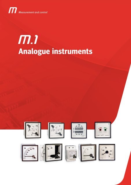
Measurement and control<strong>Analogue</strong> <strong>instruments</strong>
<strong>Analogue</strong> <strong>instruments</strong><strong>Analogue</strong> <strong>instruments</strong>Introduction ....................................................................................... 4Product selection table .............................................................................. 7EC / EM / EZC / EC FA / CEC 96Moving iron ammeters (AC) .......................................................................... 8EC / EM / EZC / ECF / EC FN / CEC 96Moving iron voltmeters (AC). ........................................................................13BC / BM / CBC 96Moving-coil ammeter (DC) ..........................................................................18BC / BM / CBC 96Moving-coil voltmeter (DC) ..........................................................................21BC / BM / ZC<strong>Analogue</strong> indicator to measure a process signal ....................................................... 24MC / MMC / EMCPower demand meters. <strong>Analogue</strong> indicator to measure alternating current and its maximeter ................. 27HC / HM / HZCHLCPointer Frequency meters ..........................................................................30Reed Frequency meters ............................................................................32WMC / WTCWattmeters. <strong>Analogue</strong> indicator to measure power ..................................................... 34YMC / YTCVarmeters. <strong>Analogue</strong> indicator to measure the reactive energy ........................................... 39FEM / FETC / FMZ / FTZElectronic phase-meters ............................................................................43PIC A / PIC B / PIC EPGRInduction phase-meters ............................................................................46Bidirectional protection wattmeters .................................................................. 502 EC / 2 HC / 2 HLCSynchronisation and marine applications equipment. ................................................... 52SMC / STC / UC / CUCSynchronisation and marine applications equipment. ................................................... 55Synchro MAX / Synchro MAX PIDSynchronisation and marine applications equipment. ................................................... 58MEG - 1000CHInsulation resistance meter .........................................................................61Hours run meter ...................................................................................63Accessories ......................................................................................65M1-2
Measurement and controlM1-3
<strong>Analogue</strong> <strong>instruments</strong><strong>Analogue</strong> <strong>instruments</strong>In many applications, such as controland distribution panels, it is important tocontrol the installation quickly and visually,with no need to interpret data to detectthe installation's status.CIRCUTOR offers a solution to theseneeds with this range of products. <strong>Analogue</strong>indicators are essential to displayan instantaneous electrical value with aneedle that moves through a graduatedscale.M.1DefinitionThe main operation of these <strong>instruments</strong>is provided by the type ofmeasurement system used, either aferromagnetic system to measure alternatingcurrent or a magneto-electricsystem to measure direct current.CIRCUTOR offers equipment for bothsystems. However, most systems aregenerally used to measure alternatingcurrent.In general, analogue <strong>instruments</strong> areused because the interpretation ofelectrical parameters is quicker andmore visual. Therefore, in this case theuser simply looks at the position of theneedle and does not have to interpret anumber on a digital display.FERROMAGNETIC OR MAGNETO-ELECTRICElectric current is directly translated bya measurement element that moves theneedle. There are two types of measurementelementsFerromagnetic (AC)The ferromagnetic indicator is composedof a coil that transmits the currentmeasured, with a fixed iron elementand moving iron element in its centre,connected to the instrument's axis andneedle. The set moves by the repulsioneffect produced by the magnetic fieldbetween both iron elements and the arcdepends on the current transmitted byM1-4
<strong>Analogue</strong> <strong>instruments</strong>the coil. This system is used to measureAC and DC voltage and current between15 and 100 Hz and it measures the rootmean square of alternating current. Itcan not be used to measure rectifiedand unfiltered AC currents.Magnetoelectric(DC)The magneto-electric indicator is composedof a permanent central magnet,surrounded by a magnetic casing thatguarantees the insensitivity to the exteriormagnetic field and there is a movingcoil between both, where the needleis fixed. Two spiral springs createthe antagonistic pair to move the needleon the scale zero. This system isused to measure DC currents and voltages,measuring mean values.Electrical and mechanical featuresInsulation voltage2 kV, 50 Hz, 1min between the mechanismand the box and between electricallyinsulated terminals.Permanent overloadsVoltage circuits: 1.2 U nCurrent circuits: 1.2 I n(1.5 I nfor moving iron)Short duration overloadsVoltage circuits:2 U nduring 5 sCurrent circuits:5 I nduring 30 s10 I nduring 5 s40 I nduring 1 sRelaysContacts: NO / NCInterrupting power: 230 V ac,8 A / 30 V dc, 5 A resistive loadFactors that influence the ClassAssembly positionAll <strong>instruments</strong> will be assembled ina vertical position. They can be suppliedfor vertical or horizontal assembly,on demand. The tolerance is ±5º.Room temperatureThe effects of temperature on the Classdepend on the scope of the measurement.In general, <strong>instruments</strong> maintaintheir Class between +10 and +30ºC.This interval can be lower for particularlylow measurement scopes. In thesecases, the limit values are indicated onthe scale.The <strong>instruments</strong> can be adjusted fortemperatures out of the interval mentionedabove, on demand.Temperaturelimits Measurement <strong>instruments</strong> andtheir accessories support variations intemperature between -25 and +40 ºC(55 ºC in the tropicalized version) withno permanent defects.Relative humidityThe Class is maintained within the 25and 80 % non-condensing relative humidityinterval.Magnetic fieldAll <strong>instruments</strong> maintain their Class underthe influence of an exterior magneticfield with a value of ≤ 0.5 MV.Ferromagnetic supportThe nature and thickness of the panel'splate does not affect the Class,with the exception of highly sensi-M1-5
<strong>Analogue</strong> <strong>instruments</strong>Moving iron ammeters (AC)Moving-coilAmmeter<strong>Analogue</strong> indicator to measurealternating currentDescription}}No need for auxiliary power supply, onlythe CEC 96 type.}}DIN boxes with dimensions: 48, 72, 96and 144.}}Precision class 1.5}}Measurement in true root mean square100 mA ... 100 A}}Exchangeable scales for EC48, EC72,EC96, EM 45, EC 72 FA, EC 96 FA}}The alarm system can be fully configuredfor CEC 96ApplicationIn alternating current applications, to controlthe state of the current quickly and visually.FeaturesEC EM EZC EC FA CEC 96 with 2 relaysAuxiliary power supply230 V acConsumption - 2.5 V·AFrequency - 40 ... 90 HzInput circuitConsumption 0.3 ... 1.5 V·A 0.2 V·AFrequency 20 ... 100 Hz 45 ... 65 Hz1.2 I npermanentOverloads5 I nduring 30 s10 I nduring 5 s1.2 I npermanent40 I nduring 1 sClass1.5 % FSAmbient conditionsOperating temperature +10 ... +30 ºC + 5 ... +55 ºCLimit temperature - 25 ... +40 ºC -25 ... +70 ºCAltitude2000 mBuild featuresDimensionsWeightSee the following tableSee the following tableType of box panel DIN rail panel panel panelDegree of protection:Front panelTerminalsInsulation voltageStandardsIP 52IP 002 kV, 50 Hz, 1 min, between the mechanismand the boxBS 89, EN 60051, IEC 144, UL 94,DIN 43780, IEC 51, UNE 21318, CEIP 52IP 203 kV , 50 Hz, 1minIEC 51, IEC 1010, IEC 529,IEC 255, IEC 278, IEC 414,IEC 144, LLOYD'S(TEST. ESP. No. 1)M1-8
<strong>Analogue</strong> <strong>instruments</strong>Moving iron ammeters (AC)Moving iron ammeter<strong>Analogue</strong> indicator to measurealternating currentReferencesAmmeters, 90ºType EC 48 EC 72 EC 96 EC 144 EM 45Class 1,5Scale (mm)Dimensions (mm)abc484866,2727249,290º , P2969649,214414471,8855265Weight (g) 85 180 220 430 142mA100 M10111 M10121 M10131 M10142 M10151150 M10112 M10122 M10132 M10142 M10152250 M10114 M10124 M10134 M10144 M10154300 M10115 M10125 M10135 M10145 M10155400 M10116 M10126 M10136 M10146 M10156500 M10117 M10127 M10137 M10147 M10157600 M10118 M10128 M10138 M10148 M10158A5 M10212 M10222 M10232 M10242 M1025210 M10213 M10223 M10233 M10243 M1025315 M10214 M10224 M10234 M10244 M1025420 M10215 M10225 M10235 M10245 M1025525 M10216 M10226 M10236 M10246 M1025630 M10217 M10227 M10237 M10247 M1025740 M10218 M10228 M10238 M10248 M1025850 M10219 M10229 M10239 M10249 M1025960 M1021A M1022A M1023A M1024A M1025A75 - M1022B M1023B M1024B -100 - M1022C M1023C M1024C -.../5 A (*) M10210 M10220 M10230 M10240 M10250Ammeters, 240ºAmmeters withphase switchAmmeterswith 2 relaysType EZC 72 EZC 96 EC 72 FA EC 96 FA CEC 96AccuracyclassScale (mm) 240º, P2 90 or , P1 90 or , P2Dimensions (mm)abc727249,2969649,2727249,21,5969649,2969685,3Weight (g) 180 220 180 220 435mA.../5 A (*) M10920 M10930 M10521 M10531 M14810* EZC 72 / EZC96:Scale included, indicate the transformer ratio.../1 A , on demandDifferent settings, on demand* EC 72 FA / EC96 FA:Scale not includedExchangeable scales (see tables).../1 A , on demandDifferent settings, on demand* CEC 96:Scale included, indicate the transformer ratioExchangeable scales (see tables).../1 A , on demand*Scale is not included, except in EC144 (equipment + scale included,indicate transformer ratio).*For exchangeable scales, see Tables.* .../1 A on demand* Different settings, on demand.M1-9
<strong>Analogue</strong> <strong>instruments</strong>Moving iron ammeters (AC)Moving iron ammeter<strong>Analogue</strong> indicator to measurealternating currentReferencesExchangeable scales, Moving Iron AmmetersType SEC 48 SEC 72 SEC 96 SEM 45 SEC 72 FA SEC 96 FAEquipment EC 48 EC 72 EC 96 EM 45 EC 72 FA EC 96 FAA5/5 M102Z2 M102Y2 M102X2 - - -10/5 M102Z3 M102Y3 M102X3 - - -15/5 M102Z4 M102Y4 M102X4 - - -20/5 M102Z5 M102Y5 M102X5 - - -25/5 M102Z6 M102Y6 M102X6 - - -30/5 M102Z7 M102Y7 M102X7 - - -40/5 M102Z8 M102Y8 M102X8 - - -50/5 M102Z9 M102Y9 M102X9 M105X9 M105Y9 M105X960/5 M102ZA M102YA M102XA M105XA M105YA M105XA75/5 M102ZB M102YB M102XB M102VB M105YB M105XB100/5 M102ZC M102YC M102XC M102VC M105YC M105XC125/5 M102ZD M102YD M102XD M102VD M105YD M105XD150/5 M102ZE M102YE M102XE M102VE M105YE M105XE200/5 M102ZF M102YF M102XF M102VF M105YF M105XF250/5 M102ZG M102YG M102XG M102VG M105YG M105XG300/5 M102ZH M102YH M102XH M102VH M105YH M105XH400/5 M102ZJ M102YJ M102XJ M102VJ M105YJ M105XJ500/5 M102ZK M102YK M102XK M102VK M105YK M105XK600/5 M102ZL M102YL M102XL M102VL M105YL M105XL750/5 M102ZM M102YM M102XM M102VM M105YM M105XM800/5 M102ZN M102YN M102XN M102VN M105YN M105XN1 000/5 M102ZP M102YP M102XP M102VP M105YP M105XP1 200/5 M102ZQ M102YQ M102XQ M102VQ M105YQ M105XQ1 500/5 M102ZR M102YR M102XR M102VR M105YR M105XR2 000/5 M102ZS M102YS M102XS M102VS M105YS M105XS2 500/5 M102ZT M102YT M102XT M102VT M105YT M105XT3 000/5 M102ZU M102YU M102XU M102VU M105YU M105XU4 000/5 M102ZV M102YV M102XV M102VV M105YV M105XV5 000/5 M102ZW M102YW M102XW M102VW M105YW M105XWM1-10
<strong>Analogue</strong> <strong>instruments</strong>Moving iron ammeters (AC)Moving iron ammeter<strong>Analogue</strong> indicator to measurealternating currentCoding tableM 1 X X X X 0 0 X X XM 1 X X X X 0 0 XCodeSettingInternalCodeStandard 2P 01P 15P 6EC and EMMilliammetersCodeSettingInternalCodeStandard 2P 01P 15P 6CurrentStandard (... / 5 A) 0EC and EZC AmmetersinputScales (*)... / 1 A 11 15 210 315 420 525 630 740 850 960 A75 B100 C125 D150 E200 F250 G300 HEC Scales andAmmeters and EMscalesAmmeters and ECFA scalesM 1 X X X X 0 0 X XCodeSettingCurrentinputInternalCodeStandard 2P 01P 15P 6Standard (.../ 5 A) 0... / 1 A 1M 1 X X X X 0 0 X XCodeSettingCurrentinputInternalCodeStandard 1P 05P 6Standard (.../ 5 A) 0... / 1 A 1400 J500 K600 L750 M800 N1000 P1200 Q1500 R2000 S2500 T3000 U4000 V5000 WCEC AmmetersM 1 X X X X 0 0 X XInternalCodeCode100 C125 D150 E200 F250 G300 H400 JScale500 K600 L750 M800 N1000 P1200 Q2000 R2500 SCurrent Standard (.../ 5 A) 0input... / 1 A 1M1-11
<strong>Analogue</strong> <strong>instruments</strong>Moving iron ammeters (AC)Moving iron ammeter<strong>Analogue</strong> indicator to measurealternating currentDimensionsECEZCType Fig. EC a b c d e48 mm 1 -3 48 44,7 61 5,2 4572 mm 1 -3-4 72 67,2 43,5 5,7 6896 mm 1 -3-4 96 91 43,5 5,7 92144 mm 2 -3-4 144 137 64,5 7,3 138Type Fig. EZC a b c d e72 mm 1 72 67,2 43,5 5,7 6896 mm 1 96 91 43,5 5,7 92Dimensions (mm)Dimensions (mm)EC-FA EM 45Type Fig. EC a b c d e72 mm 1 -3-4 72 67,2 43,5 5,7 68 +0,896 mm 1 -3-4 96 91 43,5 5,7 92 +0,8Dimensions (mm)ConnectionsEC / EZC EC-FA EM 45M1-12
<strong>Analogue</strong> <strong>instruments</strong>Moving iron voltmeters (AC)Moving ironvoltmeter<strong>Analogue</strong> indicator to measurealternating currentDescription}}No need for auxiliary power supply, onlythe CEC 96 type}}DIN boxes with dimensions: 48, 72, 96and 144}}Precision class 1.5}}Measurement in true root mean square orV ... 600 V ac}}Exchangeable scales for EC48, EC72,EC96, EM 45}}The alarm system can be fully configuredfor CEC 96ApplicationIn alternating current applications, to controlthe state of the voltage quickly and visually.FeaturesAuxiliary power supplyEC EM EZC EC F EC FN CEC 96230 V acConsumption - 2.5 V·AFrequency - 40 ... 90 HzInput circuitConsumption 1 ... 4 V·A 0.2 V·AFrequency 20 ... 100 Hz 45 ... 65 HzOverloads1.5 U npermanent2 U nduring 5 s1.2 U npermanentClass1.5 % FSAmbient conditionsOperating temperature +10 ... +30 ºC + 5 ... +55 ºCLimit temperature - 25 ... +40 ºC -25 ... +70 ºCAltitude2000 mBuild featuresDimensionsSee the following tableWeightType of boxDegree of protection:Front panelterminalsInsulation voltageStandardspanelDINrailIP 52IP 002 kV, 50 Hz, 1 min, between themechanism and the boxBS 89, EN 60051, IEC 144, UL 94,DIN 43780, IEC 51, UNE 21318, CESee the following tablepanel panel panel panelIP 52IP 203 kV , 50 Hz, 1minIEC 51, IEC 1010, IEC 529,IEC 255, IEC 278, IEC 414,IEC 144, LLOYD'S(TEST. ESP. No. 1)M1-13
<strong>Analogue</strong> <strong>instruments</strong>Moving iron voltmeter (AC)Moving iron voltmeter<strong>Analogue</strong> indicator to measurealternating currentCoding tableEC Voltmeters through transformer and EZCM 1 X X X X 0 0 X X XInternalCodeCodeSettingStandard 1.2P 01P 1Standard (.../110 V) 0.../100 V 1Voltage input.../63.5 V 2.../57.8 V 3Scales (for1000 1equipment3300 2with inputs6600 3through the13200 4transformer15000 5and all ECs)20000 622000 7Direct EC and EC FvoltmetersEC Scales andVoltmeter and EM scaleM 1 X X X X 0 0 XCodeSettingInternalCodeStandard 1P 01.2P 2M 1 X X X X 0 0 X XCodeSettingVoltage inputInternalCodeStandard 1.2P 01P 1Standard (.../110 V) 0.../100 V 1.../63.5 V 225000 8.../57.8 V 3M1-16
<strong>Analogue</strong> <strong>instruments</strong>Moving iron voltmeter (AC)Moving iron voltmeter<strong>Analogue</strong> indicator to measurealternating currentDimensionsECEZCType Fig. EC a b c d e48 mm 1 -3 48 44,7 61 5,2 4572 mm 1 -3-4 72 67,2 43,5 5,7 6896 mm 1 -3-4 96 91 43,5 5,7 92144 mm 2 -3-4 144 137 64,5 7,3 138Type Fig. EZC a b c d e72 mm 1 72 67,2 43,5 5,7 6896 mm 1 96 91 43,5 5,7 92Dimensions (mm)Dimensions (mm)EC-FN / EC-F EM 45Type Fig. EC a b c d e72 mm 1 -3-4 72 67,2 43,5 5,7 68 +0,896 mm 1 -3-4 96 91 43,5 5,7 92 +0,8Dimensions (mm)ConnectionsEC / EZC EC-F EC-FNEM 45M1-17
<strong>Analogue</strong> <strong>instruments</strong>Moving-coil ammeter (DC)Moving-coilammeter<strong>Analogue</strong> indicator to measure directcurrentDescriptionFeatures}}No need for auxiliary power supply, onlythe CEC 96 type}}DIN boxes with dimensions: 48, 72, 96and 144}}Precision class 1.5}}Measurement in DC 25 uA ... 60 A, or ...60 mV}}Exchangeable scales for BC48, BC72,BC96, BM 45}}The alarm system can be fully configuredfor CBC 96ApplicationIn direct current applications, to control thestate of the current quickly and visually.Auxiliary power supplyBC BM CBC 96230 V acConsumption - 2.5 V·AFrequency - 40 ... 90 HzInput circuitConsumption 60 mV 0.2 V·AOverloadsClass1.2 I npermanent5 I nduring 30 s10 I nduring 5 s40 I nduring 1 s1.5 % FS1.2 I npermanent5 I nduring 30 s10 I nduring 5 s40 I nduring 1 sAmbient conditionsOperating temperature +10 ... +30 ºC + 5 ... +55 ºCLimit temperature - 25 ... +40 ºC -25 ... +70 ºCAltitude2000 mBuild featuresDimensionsSee the following tableWeightSee the following tableType of box panel DIN rail panelDegree of protection:Front panelterminalsInsulation voltageStandardsIP 52IP 00IP 52IP 202 kV, during 1 min, between the mechanism and the boxBS 89, EN 60051, IEC 144, UL 94, DIN43780, IEC 51, UNE 21318, CEIEC51, IEC 1010, IEC 529,IEC 255, IEC 278, IEC 414,IEC 144, LLOYD’S(TEST. ESP. No. 1)M1-18
<strong>Analogue</strong> <strong>instruments</strong>Moving-coil ammeter (DC)Moving-coil ammeter<strong>Analogue</strong> indicator to measuredirect currentReferencesBC: Ammeters 90º / BM: Ammeters 90º, DIN rail / CBC96: Ammeters with 2 relaysExchangeable scalesAmmeters, 90ºAmmeterswith 2 relaysType BC 48 BC 72 BC 96 BC 144 BM 45 CBC 96Class 1,5 1,5Scale 90º , P1 90º , P1Dimensions (mm)abc484866,2727249,2969649,214414471,8855265969685,3Weight (g) 75 170 210 420 110 435A5 M11412 M11422 M11432 M11442 M11452 -10 M11413 M11423 M11433 M11443 M11453 -25 M11416 M11426 M11436 M11446 M11456 -50 M11419 M11429 M11439 M11449 M11459 -60 - M1142A M1143A M1144A M1145A -.../60 mV(*) M11410 M11420 M11430 M11440 M11450 M14830* BC48 / BC 72 / BC96 / BC144 / BM45:*Scale is not included, except in EC144 (equipment + scale included, indicate transformer ratio)*For exchangeable scales, see Tables. External shunts, see M.7*Different input ranges, shunt*Central zero adjustment, on demand*Inputs starting on 25 uA, on demandType SBC 48 SBC 72 SBC 96 SBM 45Equipment BC 48 BC 72 BC 96 BM 45A / mV50/60 M114Z9 M114Y9 M114X9 M114V960/60 M114ZA M114YA M114XA M114VA75/60 M114ZB M114YB M114XB M114VB100/60 M114ZC M114YC M114XC M114VC150/60 M114ZE M114YE M114XE M114VE200/60 M114ZF M114YF M114XF M114VF250/60 M114ZG M114YG M114XG M114VG300/60 M114ZH M114YH M114XH M114VH400/60 M114ZJ M114YJ M114XJ M114VJ600/60 M114ZL M114YL M114XL M114VL1 000/60 M114ZP M114YP M114XP M114VP1 500/60 M114ZR M114YR M114XR M114VR2 500/60 M114ZT M114YT M114XT M114VT* If the input of the unit requested is not .../60mV,indicate the ratio.* CEC 96:*Scale included, indicate the transformer ratio (shunt)Coding tableM 1 X X X X 0 0 X X XM 1 X X X X 0 0 X XBC and BM45 AmmetersCodeSettingShunt inputrangeScalesInternalCodeStandard 0Central zero 1Standard (.../60 mV) 0.../50 mV 1.../150 mV 3.../300 mV 550 960 A75 B100 C150 E200 F250 GSBC and SBM45 ScalesCodeSettingShunt inputrangeInternalCodeStandard 0Central zero 1Standard (.../60 mV) 0.../50 mV 1.../150 mV 3.../300 mV 5300 H400 J500 K600 L1000 P1500 R2500 TM1-19
<strong>Analogue</strong> <strong>instruments</strong>Moving-coil ammeter (DC)Moving-coil ammeter<strong>Analogue</strong> indicator to measure DC currentReferencesBCCBCBM 45Type Fig. BC a b c d e48 mm 1 -3 48 44,7 61 5,2 4572 mm 2 -3-4 72 67,2 43,5 5,7 6896 mm 2 -3-4 96 91 43,5 5,7 92144 mm 2 -3-4 144 137 64,5 7,3 138Dimensiones (mm)ConnectionsBCCBCBM 45M1-20
<strong>Analogue</strong> <strong>instruments</strong>Moving-coil voltmeter (DC)Moving-coilVoltmeter<strong>Analogue</strong> indicator to measure DCvoltageDescription}}No need for auxiliary power supply, onlythe CEC 96 type}}DIN boxes with dimensions: 48, 72, 96and 144}}Precision class 1.5}}Measurement in DC 25 uA ... 60 A, or ...60 mV}}Exchangeable scales for BC48, BC72,BC96, BM 45}}The alarm system can be fully configuredfor CBC 96ApplicationIn direct current applications, to control thestate of the current quickly and visually.FeaturesAuxiliary power supplyBC BM CBC 96230 V acConsumption - 2.5 V·AFrequency - 40 ... 90 HzInput circuitConsumption 1000Ω 0.2 V·AFrequency 20 ... 100 Hz 45 ... 65 HzOverloads1.5 U npermanent2 U npermanent 5 s1.2 U npermanentTemp. Coefficient 100 ppm / ºCClass1.5 % FSAmbient conditionsOperating temperature +10 ... +30 ºC + 5 ... +55 ºCLimit temperature - 25 ... +40 ºC -25 ... +70 ºCAltitude2000 mBuild featuresDimensionsSee the following tableWeightSee the following tableType of box panel DIN rail panelDegree of protection:Front panelterminalsInsulation voltageStandardsIP 52IP 00IP 52IP 202 kV, during 1 min, between the mechanism and the boxBS 89, EN 60051, IEC 144, UL 94, DIN43780, IEC 51, UNE 21318, CEIEC51, IEC 1010, IEC 529,IEC 255, IEC 278, IEC 414,IEC 144, LLOYD’S(TEST. ESP. No. 1)M1-21
<strong>Analogue</strong> <strong>instruments</strong>Moving-coil voltmeter (DC)Moving coil voltmeter<strong>Analogue</strong> indicator to measure DC voltageReferencesBC: Voltmeters 90ºBM: Voltmeters 90º, DIN railCBC96: Voltmeters with relay 90ºVoltmeters, 90ºVoltmeters with relayType BC 48 BC 72 BC 96 BC 144 BM 45 CBC 96Class 1,5Scale 90º , P1 90º , P1Dimensions (mm)abc484866,2*Scale not included, indicate voltage input*Inputs of more than 10 mV, on demand727249,2969649,214414471,8Weight (g) 75 170 210 420 110 435855265969685,3V0..0.10 V M11813 M11823 M11833 M11843 - -1 M11711 M11721 M11731 M11741 - -15 M11714 M11724 M11734 M11744 M11754 -30 M11716 M11726 M11736 M11746 M11755 -60 M11718 M11728 M11738 M11748 M11756 -100 M11719 M11729 M11739 M11749 M11757 -150 M1171A M1172A M1173A M1174A M11758 M14841250 M1171B M1172B M1173B M1174B - M14842300 - - - - - M14843400 M1171D M1172D M1173D M1174D - M14844500 M1171E M1172E M1173E M1174E - M14845600 M1171F M1172F M1173F M1174F - M14846Coding tableM 1 X X X X 0 0 XBC and BMVoltmetersCodeSettingInternalCodeStandard 0Central zero 1M1-22
<strong>Analogue</strong> <strong>instruments</strong>Moving-coil voltmeter (DC)Moving coil voltmeter<strong>Analogue</strong> indicator to measure DC voltageReferencesBCCBCBM 45Type Fig. BC a b c d e48 mm 1 -3 48 44,7 61 5,2 4572 mm 2 -3-4 72 67,2 43,5 5,7 6896 mm 2 -3-4 96 91 43,5 5,7 92144 mm 2 -3-4 144 137 64,5 7,3 138Dimensiones (mm)ConnectionsBCCBCBM 45M1-23
<strong>Analogue</strong> <strong>instruments</strong>Processindicators<strong>Analogue</strong> indicator to measurea process signalDescription}}Does not need an auxiliary power supply}}DIN boxes with dimensions: 48, 72, 96and 144}}Precision class 1.5}}Measurement in DC of 0 ... 10 V, 0/4 ...20 mA, .../60 mV}}Exchangeable scales for BC48, BC72,BC96, BM 45FeaturesInput circuitBC BM ZCConsumption 1000Ω V·AOverloads1.5 U npermanent2 U npermanent 5 sClass1.5 % FSAmbient conditionsOperating temperature +10 ... +30 ºCLimit temperature - 25 ... +40 ºCApplicationFor the measurement of the mean value ofvoltages and currents in direct current circuits,even of the pulsating type, in a vastmargin of values.Altitude2000 mBuild featuresDimensionsSee the following tableWeightSee the following tableType of box panel DIN rail panelDegree of protection:Front panelterminalsIP 52IP 00IP 52IP 20Insulation voltage2 kV, during 1 min, between the mechanism and the boxStandards BS 89, EN 60051, IEC 144, UL 94, DIN 43780, IEC 51, UNE 21318M1-24
<strong>Analogue</strong> <strong>instruments</strong>Process indicators<strong>Analogue</strong> indicator to measurea process signalReferencesBC: Process indicators 90ºCoding tableM 1 X X X X 0 0 X XCodeInternalCodeProcess indicators, 90ºType BC 48 BC 72 BC 96 BC 144 BM 45Class 1,5ScaleDimensions (mm)abc484866,2727249,290º , P1969649,214414471,8855265Weight (g) 75 170 210 420 110Scope0..0.10 V M11813 M11823 M11833 M11843 M118530...20 mA M11812 M11822 M11832 M11842 M118524...20 mA M11811 M11821 M11831 M11841 M11851.../60 mV - - - - -ZC: Process indicators, 240ºProcess indicators, 240ºType ZC 48 ZC 72 ZC 96 ZC 144class 1,5ScaleDimensions (mm)abc484866,2727249,2240º, P1969649,214414471,8Weight (g) 75 170 210 420Scope0..0.10 V M12513 M12523 M12533 M125430...20 mA - - - -4...20 mA M12511 M12521 M12531 M12541.../60 mV M12510 M12520 M12530 M12540Exchangeable scalesType SIP 48 SIP 72 SIP 96 SIPM 45Equipment BC 48 BC 72 BC 96 BM 45Scope0..0.10 V M118Z3 M118Y3 M118X3 M118V30...20 mA M118Z2 M118Y2 M118X2 M118V2BC and ZC process indicatorsSettingScaleStandard 0Central zero 11 15 210 315 420 525 630 740 850 960 A75 B100 C125 D150 E200 F250 G300 H400 J500 K600 L750 M800 N1000 P1200 Q1500 R2000 S2500 T3000 U4000 V5000 W- 0mA 1A 2kA 3mV 4V 8kV 9rpmArpm x 1000Bl (litres)CmGm 2m 3HJ% K4...20 mA M118Z1 M118Y1 M118X1 M118V1M1-25
<strong>Analogue</strong> <strong>instruments</strong>Process indicators<strong>Analogue</strong> indicator to measurea process signalDimensionsZCBCType Fig. ZC a b c d e48 mm 1 48 44,7 61 5,2 4572 mm 1 72 67,2 43,5 5,7 6896 mm 1 96 91 43,5 5,7 92144 mm 1 144 137 64,5 7,3 138Dimensiones (mm)Type Fig. BC a b c d e48 mm 1 -3 48 44,7 61 5,2 4572 mm 2 -3-4 72 67,2 43,5 5,7 6896 mm 2 -3-4 96 91 43,5 5,7 92144 mm 2 -3-4 144 137 64,5 7,3 138Dimensiones (mm)BMConnectionsBC / ZCBMM1-26
<strong>Analogue</strong> <strong>instruments</strong>Power demand meters<strong>Analogue</strong> indicator to measurealternating current and its maximeterDescription}}Does not need an auxiliary power supply}}DIN boxes with dimensions 48, 72, 96and 144}}Class 3}}Measurement in AC of .../5 A (on demand.../1A)}}Exchangeable scales for MC48, MC72,MC96, MM 45, EMC72, EMC96}}Thermal inertia times of 15 min (on demand,8 and 30 min)FeaturesInput circuitMC MMC EMCConsumption 3.25 V·A 4.25 V·A1.5 IOverloadsnpermanent15 I nduring 1 sAccuracy ± 3 % FS ± 3 % Bim.± 1.5 % HMAmbient conditionsOperating temperature +10 ... +30 ºCLimit temperature - 25 ... +40 ºCApplicationAltitudeBuild featuresDimensions2000 mSee the following tableTo control the alternating current and measurelong overloads in the same unit, integratedwithin a determined period.WeightSee the following tableType of box panel DIN rail panelDegree of protection:Front panelterminalsIP 52IP 00IP 52IP 00Insulation voltage2 kV, during 1 min, between the mechanism and the boxStandards BS 89, EN 60051, IEC 144, UL 94, DIN 43780, IEC 51, UNE 21318M1-27
<strong>Analogue</strong> <strong>instruments</strong>Power demand meters<strong>Analogue</strong> indicator to measurealternating current and its maximeterReferencesMC: Bimetallic power demand ammeters, 90ºMMC: Bimetallic power demand ammeters,90º, DIN railEMC: Bimetallic power demand ammeters+ Moving iron ammeter, 90ºBimetallic maximeter ammetersType MC 48 MC 72 MC 96 MC 144 MMC 45class 3Scale 90º , P1.2Dimensions (mm)abc484866,2727249,2969649,214414471,8Weight (g) 110 140 210 420855265A... / 5 A M12211 M12221 M12231 M12241 M12651Bimetallic maximeter ammeters + Moving iron ammeterType EMC 72 EMC 96 EMC 144class Bimetallic: 3 Moving iron: 1,5ScaleDouble scale 90º, bimetallic: P1.2, moving iron P2Dimensions (mm)abc727249,2969649,214414471,8Weight (g) 220 260 470A... / 5 A M12622 M12632 M12642* Scale not included. Indicate transformer ratio* For exchangeable scales, see Tables* Scale not included. Indicate transformer ratio* For exchangeable scales, see TablesExchangeable scalesExchangeable scalesType SMC 48 SMC 72 SMC 96 SMMC 45-A SEMC 72 SEMC 96Equipment MC 48 MC 72 MC 96 MMC 45 EMC 72 EMC 72A100/5 M122ZC M122YC M122XC M126VC M126YC M126XC200/5 M122ZF M122YF M122XF M126VF M126YF M126XF300/5 M122ZH M122YH M122XH M126VH M126YH M126XH400/5 M122ZJ M122YJ M122XJ M126VJ M126YJ M126XJ500/5 M122ZK M122YK M122XK M126VK M126YK M126XK600/5 M122ZL M122YL M122XL M126VL M126YL M126XL750/5 M122ZM M122YM M122XM M126VM M126YM M126XM800/5 M122ZN M122YN M122XN M126VN M126YN M126XN1 000/5 M122ZP M122YP M122XP M126VP M126YP M126XP1 500/5 M122ZR M122YR M122XR M126VR M126YR M126XR2 000/5 M122ZS M122YS M122XS M126VS M126YS M126XS* If the input of the unit requested is not .../5 A, indicate the ratio.M1-28
<strong>Analogue</strong> <strong>instruments</strong>Power demand meters<strong>Analogue</strong> indicator to measurealternating current and its maximeterCoding tableDimensionsM 1 X X X X 0 0 XEMC / MCMMC 45 powerdemandCodeSettingStandard(15 minutes)InternalCode08 minutes 130 minutes 2Type a b c d eMC 48 48 44,7 61 5,2 45 +0,8MC and EMC Power demand meters and SMC and SEMC ScalesM 1 X X X X 0 0 X X XCodeSettingCurrentinputScaleInternalCodeStandard (15minutes)08 minutes 130 minutes 2Standard (.../ 5 A) 0... / 1 A 1100 C125 D150 E200 F250 G300 H400 J500 K600 L750 M800 N1000 P1200 Q1500 R2000 S2500 T3000 U4000 V5000 WMC 72 72 67,2 43,5 5,7 68 +0,8EMC 72 72 67,2 57,2 5,7 68 +0,8EMC 96 96 91 43,5 5,7 92 +0,8EMC 144 144 137 64,5 7,3 138 +1Dimensions (mm)MMCConnectionsEMC / MCMMCM1-29
<strong>Analogue</strong> <strong>instruments</strong>PointerFrequency meters<strong>Analogue</strong> indicator to measurefrequencyDescriptionFeatures}}Does not need an auxiliary power supply}}DIN box with dimensions: 48, 72, 96 and144}}Class 0.5}}Built-in electronic converterApplicationInput circuitConsumptionFrequencyOverloadsMeasurement voltageHC HM HZC2 ... 3 V·A50 ... 400 Hz1.5 I npermanent15 I nduring 1 sStandard 230 VacOptional 100-120 Vac380-440 VacAccurate and easy reading of frequency inalternating current circuits. The distortionof voltage (we shall measure its frequency)can reach 15% of the nominal voltage in thethird order harmonic, while the Class is notaffected.Accuracy0.5 % FSAmbient conditionsOperating temperature +10 ... +30 ºCLimit temperature - 25 ... +40 ºCAltitude2000 mBuild featuresDimensionsWeightSee the following tableSee the following tableType of box panel DIN rail panelDegree of protection:Front panelTerminalsIP 52IP 00IP 52IP 00Insulation voltage2 kV, during 1 min, between the mechanism and the boxStandards BS 89, EN 60051, IEC 144, UL 94, DIN 43780, IEC 51, UNE 21318Coding tableM 1 X X X X 0 0 X XReed HC, HZC and HMCodeFrequencyVoltageInternalCodeStandard (45...55 Hz) 057..0.63 Hz 155..0.65 Hz 345..0.65 Hz 447...53 Hz 5Standard (230 V) 0100 ... 120 V 1380 ... 400 V 3440 V 4M1-30
<strong>Analogue</strong> <strong>instruments</strong>Pointer Frequency meters<strong>Analogue</strong> indicator to measure frequencyReferencesPointerFrequency meters,90ºFrequency meters, 90ºType HC 48 HC 72 HC 96 HC 144 HM 45class 0,5Scale 90ºDimensions (mm)abc484866,2727249,2969649,214414471,8Weight (g) 95 175 215 425 250Hz45...55 M12711 M12721 M12731 M12741 M1275157...63 M12711001 M12721001 M12731001 M12741001 M1275100155...65 M12711003 M12721003 M12731003 M12741003 M1275100345...65 M12711004 M12721004 M12731004 M12741004 M1275100447...63 M12711005 M12721005 M12731005 M12741005 M12751005855265PointerFrequency meters,240ºFrequency meters, 240ºType HZC 96 HZC 144class 0,5Scale 240ºDimensions (mm)abc9696101.2144144102Weight (g) 180 520Hz45...55 M12831 M1284157...63 M12831001 M1284100155...65 M12831003 M1284100345...65 M12831004 M1284100447...63 M12831005 M12841005DimensionsHCHZCType a b c d e48 48 44,7 61 5,2 45 +0,872 72 67,2 43,5 5,7 68 +0,896 96 91 43,5 5,7 92 +0,8Type a b c d e96 96 91 95,5 5,7 92 +0,8144 144 137 94,7 7,3 138 +1Dimensions (mm)144 144 137 64,5 7,3 138 +1Dimensions (mm)ConnectionsHMHC / HZCHMM1-31
<strong>Analogue</strong> <strong>instruments</strong>ReedFrequency- meters<strong>Analogue</strong> indicator to measurefrequencyDescription}}Does not need an auxiliary power supply}}DIN box with dimensions: 72, 96 and144 mm}}Class 0.5}}Independent measurement of the waveshapeApplicationMeasurement of the frequency in alternatingcurrent circuits, for any type of wave shapeand under adverse environmental and physicalconditions.FeaturesInput circuitConsumptionNominal operatingfrequencyOverloadsMeasurement voltageAccuracyHLC1 ... 3.6 V·A50 or 60 Hz1.2 U npermanent2 U nduring 5 sStandard 230 VacOptional 100...120 Vac / 380...440 Vac0.5 % FSAmbient conditionsOperating temperature +10 ... +30 ºCLimit temperature - 25 ... +40 ºCAltitude2000 mBuild featuresDimensionsWeightType of boxSee the following tableSee the following tablepanelDegree of protection:Front panelTerminalsInsulation voltageIP 52IP 002 kV, during 1 min, between the mechanism and the boxStandards BS 89, EN 60051, IEC 144, UL 94, DIN 43780, IEC 51, UNE 21318M1-32
<strong>Analogue</strong> <strong>instruments</strong>Reed Frequency meters<strong>Analogue</strong> indicator to measure frequencyReferencesCoding tableM 1 X X X X 0 0 X XReed Frequency metersType HLC 72 HLC 96 HLC 144Class 0,5Dimensions (mm)abc727249,2969649,214414471,8Weight (g) 230 300 423Hz47...53, 13 reedsM12921 M12931 M12941HLC Frequency metersCodeFrequency /No. reedsVoltageInternalCodeStandard (47...53 Hz/ 013 reeds)57...63 Hz / 13 reeds 145..0.55 Hz / 11reeds255...65 Hz / 11 reeds 357...63 Hz / 7 reeds 447..0.53 Hz / 7 reeds 5Standard (230 V) 0100 ... 120 V 1380 ... 400 V 3440 V 445..0.55, 11 reeds 50 Hz M12921002 M12931002 M1294100247...53, 7 reeds M12921005 M12931005 M1294100557..0.63, 13 reedsM12921001 M12931001 M1294100155..0.65, 11 reeds 60 Hz M12921003 M12931003 M1294100357..0.63, 7 reeds M12921004 M12931004 M12941004ConnectionsDimensions144 144 137 64,5 7,3 138 +1HLCType a b c d eHLC72 72 67,2 43,5 5,7 68 +0,896 96 91 43,5 5,7 92 +0,896 (c) 96 91 57,2 5,7 92 +0,8Dimensions (mm)M1-33
<strong>Analogue</strong> <strong>instruments</strong>Wattmeters<strong>Analogue</strong> indicator to measure activepowerDescriptionFeatures}}Does not need an auxiliary power supply}}DIN box with dimensions 96 and 144.Class 1.5}}Built-in electronic converter}}Balanced and unbalanced single andthree-phase circuits.Voltage circuitVoltageConsumptionFrequencyOverloadsWMC400 V1 ... 4 V·A45 ... 65 Hz1.25 U npermanent2 U nduring 5 sWTCApplicationCurrent circuitNominal current... 5 AMeasurement of active power in balanced orConsumption0.3 ... 1.5 V·Aunbalanced single and three-phase circuits.Frequency45 ... 65 HzOverloads1.2 I npermanent5 I nduring 30 s10 I nduring 5 s40 I nduring 1 sAccuracy± 1.5 % FSAmbient conditionsOperating temperature +10 ... +30 ºCLimit temperature - 25 ... +40 ºCAltitude2000 mBuild featuresDimensionsWeightType of boxSee the following tableSee the following tablepanelDegree of protection:Front panelTerminalsInsulation voltageIP 52IP 002 kV, during 1 min, between the mechanism and the boxStandards BS 89, EN 60051, IEC 144, UL 94, DIN 43780, IEC 51, UNE 21318M1-34
<strong>Analogue</strong> <strong>instruments</strong>Wattmeters<strong>Analogue</strong> indicator to measure active powerReferencesWMC: Single-phase wattmetersSingle-phaseType WMC 96 WMC 144Class 1,5ScaleDimensions (mm)abc969649,290º P1 (Simple profile)14414471,8Weight (g) 290 490U phase-phase400 V(*) M13031 M13041*Scale is NOT included for WMC 96. For exchangeable scales, see Tables.*Scale included for WMC 144. Indicate the transformer ratio, power andvoltage scale base.*Other voltage values, on demand.WTC: Three-phase wattmetersBalanced three-phase Three-phase 3 wires (ARON) Three-phase (4 wires)Type WTC 96E WTC 144E WTC 96A WTC 144A WTC 96AN WTC 144ANClass 1,5ScaleDimensions (mm)abc969649,214414471,8969662,990º P1 (Simple profile)Weight (g) 290 490 430 640 430 640U phase-phase 400 V 110 V 400 V14414471,8969662,914414471,8(*)M13032 M13032 M13034 M13044 (*)M13033 M13043*Scale is NOT included for WTC 96E and WTC 96AN.For exchangeable scales, see Tables.*Scale included for WTC 144E, WTC 96A, WTC144A and WTC 144AN.Indicate the transformer ratio, power and voltage scale base.*Other voltage values, on demand.M1-35
<strong>Analogue</strong> <strong>instruments</strong>Wattmeters<strong>Analogue</strong> indicator to measure active powerReferencesExchangeable scalesSingle-phase wattmetersExchangeable scalesSingle-phaseType SWM 96Equipment WMC 96A Scale Base Code50/5 20 kW M130J975/5 - -100/5 40 kW M130JC150/5 60 kW M130JE200/5 80 kW M130JF300/5 120 kW M130JH400/5 160 kW M130JJ500/5 200 kW M130JK600/5 240 kW M130JL1 000/5 400 kW M130JP1 500/5 600 kW M130JR2 000/5 800 kW M130JS3 000/5 1.2 MW M130JU4 000/5 1.6 MW M130JV5 000/5 2.0 MW M130JWThree-phase wattmetersExchangeable scalesThree-phaseType SWT 96E SWT 96ANEquipment WTC 96E WTC 96ANA Scale Base Code Code50/5 30 kW M130K9 M130L975/5 50 kW M130KB M130LB100/5 60 kW M130KC M130LC150/5 90 kW M130KE M130LE200/5 120 kW M130KF M130LF300/5 180 kW M130KH M130LH400/5 240 kW M130KJ M130LJ500/5 300 kW M130KK M130LK600/5 360 kW M130KL M130LL1 000/5 600 kW M130KP M130LP1 500/5 900 kW M130KR M130LR2 000/5 1.2 MW M130KS M130LS3 000/5 1.8 MW M130KU M130LU4 000/5 2.4 MW M130KV M130LV5 000/5 3 MW M130KW M130LWM1-36
<strong>Analogue</strong> <strong>instruments</strong>Wattmeters<strong>Analogue</strong> indicator to measure active powerCoding tableM 1 X X X X 0 0 X X XCodeCurrent inputInternalCodeStandard .../ 5 A 0... / 1 A 1Standard (400 V p-p) 0110 V p-p(a) 1Voltage230 V p-p2440 V p-p5460 V p-p6WattmetersScale rangePrimarycurrenttransformer50 975 B100 C150 E200 F300 H400 J500 K600 L1000 P1500 R2000 S3000 U4000 V5000 W(a) For unbalanced ARON (3 wire) three-phase units, 100 V isconsidered the standard voltageM 1 X X X X 0 0 X XWattmeter scalesCodeCurrent inputVoltageInternalCodeStandard .../ 5 A 0... / 1 A 1Standard (400 V) 0110 V (a) 1230 V 2440 V 5460 V 6(a) For unbalanced ARON (3 wire) three-phase units, 100 V isconsidered the standard voltageM1-37
<strong>Analogue</strong> <strong>instruments</strong>Wattmeters<strong>Analogue</strong> indicator to measure active powerDimensionsWMC / WTCType a b c d e96 E 96 91 43,5 5,7 92 +0,896 A / AN 96 91 57,2 5,7 92 +0,8144 144 137 94,7 7,3 138 +1Dimensions (mm)ConnectionsWMCWTCEWTCAWTCANM1-38
<strong>Analogue</strong> <strong>instruments</strong>Varmeters<strong>Analogue</strong> indicator to measurereactive powerDescription}}Does not need an auxiliary power supply}}DIN box with dimensions 96 and 144.}}Class 1.5}}Built-in electronic converter}}Balanced and unbalanced single andthree-phase circuits.ApplicationMeasurement of the power factor in balancedor unbalanced single and three-phasecircuits.FeaturesVoltage circuitYMCVoltage 400 V ( *1 )Consumption1 ... 4 V·AFrequency 50 Hz ( *1 ) 20 ... 100 HzOverloads1.25 U npermanent2 U nduring 5 sCurrent circuitNominal current ... 5 A ( *1 )Consumption0.3 ... 1.5 V·AFrequency 50 Hz ( *1 ) 20 ... 100 Hz1.2 I npermanent5 IOverloadsnduring 30 s10 I nduring 5 s40 I nduring 1 sYTCAccuracy± 1.5 % FSAmbient conditionsOperating temperature +10 ... +30 ºCLimit temperature - 25 ... +40 ºCAltitude2000 mBuild featuresDimensionsWeightType of boxSee the following tableSee the following tablepanelDegree of protection:Front panelTerminalsInsulation voltageIP 52IP 002 kV, during 1 min, between the mechanism and the boxStandards BS 89, EN 60051, IEC 144, UL 94, DIN 43780, IEC 51, UNE 21318( *1 ) Other values, on demandM1-39
<strong>Analogue</strong> <strong>instruments</strong>Varmeters<strong>Analogue</strong> indicator to measurereactive powerReferencesYMC: Varmeterssingle-phaseYTC: Three-phase varmetersSingle-phaseYMC 96 YMC 144Class 1,5ScaleDimensions (mm)abc90 º P1 (simple profile)969649,214414471,8Weight (g) 290 490U phase-phaseCurrentM13231400 V... / 5 AM13241ClassScaleDimensions (mm)abcBalanced three-phaseThree-phase 3wires (ARON)Three-phase (4 wires)YTC 96E YTC 144E YTC 96A YTC 144A YTC 96AN YTC 144AN969649,214414471,890 º P1 (simple profile)969662,914414471,8969662,9Weight (g) 290 490 430 640 430 640U phase-phase400 V 110 V 400 VCurrent14414471,8M13232 M13242 M13234 M13244 M13233 M13243*Scale is NOT included for YMC 96.For exchangeable scales, see Tables.*Scale included for YMC 144. Indicatethe transformer ratio, power and voltagescale base.*Other voltage values, on demand.*Scale is NOT included for YTC 96E and YTC 96AN. For exchangeable scales, see Tables.*Scale included for YTC 144E, YTC 96A, YTC144A and YTC 144AN. Indicate the transformer ratio,power and voltage scale base.*Other voltage values, on demand.Exchangeable scalesSingle-phase varmetersExchangeable scalesSingle-phaseType SYM 96Equipment YMC 96A Scale Base Code50/5 20 kvar M132J975/5 - -100/5 40 kvar M132JC150/5 60 kvar M132JE200/5 80 kvar M132JF300/5 120 kvar M132JH400/5 160 kvar M132JJ500/5 200 kvar M132JK600/5 240 kvar M132JL1 000/5 400 kvar M132JP1 500/5 600 kvar M132JR2 000/5 800 kvar M132JS3 000/5 1.2 Mvar M132JU4 000/5 1.6 Mvar M132JV5 000/5 2.0 Mvar M132JWThree-phase varmetersExchangeable scalesThree-phaseType SYT 96E SYT 96ANEquipment YTC 96E YTC 96ANA Code Code50/5 30 kvar M132K9 M132L975/5 45 kvar M132KB M132LB100/5 60 kvar M132KC M132LC150/5 90 kvar M132KE M132LE200/5 120 kvar M132KF M132LF300/5 150 kvar M132KH M132LH400/5 240 kvar M132KJ M132LJ500/5 300 kvar M132KK M132LK600/5 360 kvar M132KL M132LL1 000/5 600 kvar M132KP M132LP1 500/5 900 kvar M132KR M132LR2 000/5 1.2 Mvar M132KS M132LS3 000/5 1.8 Mvar M132KU M132LU4 000/5 2.4 Mvar M132KV M132LV5 000/5 3.0 Mvar M132KW M132LWM1-40
<strong>Analogue</strong> <strong>instruments</strong>Varmeters<strong>Analogue</strong> indicator to measurereactive powerDimensionsYMC / YTCType a b c d e96 E 96 91 43,5 5,7 92 +0,896 A / AN 96 91 57,2 5,7 92 +0,8144 144 137 94,7 7,3 138 +1Dimensios (mm)ConnectionsYMCYTCEYTCAYTCANM1-41
<strong>Analogue</strong> <strong>instruments</strong>Varmeters<strong>Analogue</strong> indicator to measurethe reactive powerCoding tableM 1 X X X X 0 0 X X XCodeCurrent inputInternalCodeStandard .../ 5 A 0... / 1 A 1Standard (400 V p-p) 0110 V p-p(a) 1Voltage230 V p-p2440 V p-p5460 V p-p6VarmetersScale rangePrimarycurrenttransformer50 975 B100 C150 E200 F300 H400 J500 K600 L1000 P1500 R2000 S3000 U4000 V5000 W(a) For unbalanced ARON (3 wire) three-phase units, 100V isconsidered the standard voltageM 1 X X X X 0 0 X XVarmeter scalesCodeCurrentinputVoltageInternalCodeStandard .../ 5 A 0... / 1 A 1Standard (400 V) 0110 V (a) 1230 V 2440 V 5460 V 6(a) For unbalanced ARON (3 wire) three-phase units, 100V isconsidered the standard voltageM1-42
<strong>Analogue</strong> <strong>instruments</strong>ElectronicPhase-meters<strong>Analogue</strong> indicator to measure cosDescription}}Does not need an auxiliary power supply}}DIN box with dimensions 96 and 144 mm}}Class 1.5}}Built-in electronic converter}}Balanced single and three-phase circuitsFeaturesVoltage circuitFEM / FETCFMZ / FTZConsumption 1 V·A 4 V·AFrequency40 ... 70 HzOverloads1.2 U npermanent2 U nduring 5 sApplicationCurrent circuitNominal current... 5 AMeasurement of cos in balanced or unbalancedsingle and three-phase circuits.Consumption 1.5 V·A 0.75 V·AFrequency20 ... 100 Hz1.2 I npermanent5 IOverloadsnduring 30 s10 I nduring 5 s40 I nduring 1 sAccuracy± 1.5 % FSAmbient conditionsOperating temperature+10 ... +30 ºCLimit temperature - 25 ... +40 ºCAltitude2000 mBuild featuresDimensionsWeightType of boxDegree of protection:Front panelTerminalsInsulation voltageSee the following tableSee the following tablepanelIP 52IP 002 kV, during 1 min, between the mechanism and the boxStandards BS 89, EN 60051, IEC 144, UL 94, DIN 43780, IEC 51, UNE 21318M1-43
<strong>Analogue</strong> <strong>instruments</strong>Electronic phase-meters<strong>Analogue</strong> indicator to measure cosReferencesSingle-phase phase-meters 90 ºSingle-phase phase-meters 240 ºFEMC 96 FEMC 144Class 1,5ScaleDimensions (mm)abc90º P1 (Simple profile)969662,914414471,8Weight (g) 480 690V cos 0.5-1-0.5100/√3 M13431 M13441110/√3 M13432 M13442100 M13433 M13443110 M13434 M13444230 M13435 M13445400 M13436 M13446440 M13437 M13447500 M13438 M13448FMZ 96 FMZ 144Class 1,5ScaleDimensions (mm)abc240º P1 (Simple profile)9696101,214414471,8Weight (g) 500 710V cos 0.5-1-0.5100/√3 M13531 M13541110/√3 M13532 M13542100 M13533 M13543110 M13535 M13545230 M13535 M13545400 M13536 M13546440 M13537 M13547500 M13538 M13548Three-phase phase-meters 90º Three-phase phase-meters 240ºFETC 96 FETC 144Class 1,5ScaleDimensions (mm)abc90º P1 (Simple profile)969662,914414471,8Weight (g) 480 690V cos ϕ 0.5-1-0.5100/√3 - -110/√3 - -100 M1343C M1344C110 M1343D M1344D230 M1343E M1344E400 M1343F M1344F440 M1343G M1344G500 M1343H M1344HFEMC 96 FEMC 144Class 1,5ScaleDimensions (mm)abc240º P1 (Simple profile)969662,914414471,8Weight (g) 480 690V cos ϕ 0.5-1-0.5100/√3 M13431 M13441110/√3 M13432 M13442100 M13433 M13443110 M13434 M13444230 M13435 M13445400 M13436 M13446440 M13437 M13447500 M13438 M13448M1-44
<strong>Analogue</strong> <strong>instruments</strong>Electronic phase-meters<strong>Analogue</strong> indicator to measure cosDimensionsFEMC / FETCFMZ / FTZType a b c d e96 96 91 57,2 5,7 92 +0,8144 144 137 64,5 7,3 138 +1Dimensions (mm)Type a b c d e96 96 91 95,5 5,7 92 +0,8144 144 137 64,5 7,3 138 +1Dimensions (mm)ConnectionsFEMCFETCFMZFTZCoding tableM 1 X X X X 0 0 X XElectronicphase-metersCodeSecondarycurrentFrequencyInternalCodeStandard .../ 5 A 0... / 1 A 1Standard (50 Hz) 060 Hz 1M1-45
<strong>Analogue</strong> <strong>instruments</strong>InductionPhase-meters<strong>Analogue</strong> indicator to measure cosDescription}}Does not need an auxiliary power supply}}DIN box with dimensions 96 and 144.}}Class 1.5}}Balanced and unbalanced single andthree-phase circuits.}}4 quadrantsFeaturesVoltage circuitPIC A / PIC BPIC EConsumption 5 V·A / 20 mA 15 mAFrequency49.5 ... 50.5 Hz4 T - 5T59.4 ... 60.6 Hz54 ... 66 HzOverloads1.2 U npermanent2 U nduring 5 sApplicationCurrent circuitNominal current... 5 AMeasurement of cos in balanced or unbalancedsingle and three-phase circuits.Consumption 4 V·A 2.5 V·AFrequency20 ... 100 Hz1.2 I npermanent5 IOverloadsnduring 30 s10 I nduring 5 s40 I nduring 1 sAccuracy± 1.5 % FSAmbient conditionsOperating temperature +10 ... +30 ºCLimit temperature - 25 ... +40 ºCAltitudeDimensionsWeightType of boxDegree of protection:Front panelTerminalsInsulation voltage2000 mSee the following tableSee the following tablepanelIP 52IP 002 kV, during 1 min, between the mechanism and the boxStandards BS 89, EN 60051, IEC 144, UL 94, DIN 43780, IEC 51, UNE 21318M1-46
<strong>Analogue</strong> <strong>instruments</strong>Induction Phase-meters<strong>Analogue</strong> indicator to measure cosReferencesInduction Phase-meters 360°,single-phaseInduction Phase-meters 360°,three-phaseType PIC 96 A PIC 144 AClass 1,5ScaleDimensions (mm)abc9696101,2360º, P1144144102Weight (g) 1 910 1 960V cos 0-1-0110 M13631 M13641230 M13632 M13642400 M13633 M13643BALANCEDUNBALANCEDType PIC 96 B PIC 144 B PIC 96 E PIC 144 EClass 1,5ScaleDimensions (mm)abc9696101,2144144102360º, P19696101,2144144102Weight (g) 1 410 1 460 1 410 1 460V cos 0-1-0110 M13634 M13644 M13637 M13647230 M13635 M13645 M13638 M13648400 M13636 M13646 M13639 M13649DimensionsCoding tableInductionPhase-metersM 1 X X X X 0 0 XCodeSecondarycurrentInternalCodeStandard .../ 5 A 0... / 1 A 1C0 C1 C2 C3 C4 C5 C6 C7a 48 72 96 144 72 96 96 144b 44 66 89,6 137 66 89,6 89,6 137c 41 43 43 64,5 57,2 57,2 95,5 94,7d 5 5,2 5,2 7,1 5,2 5,2 5,2 7,1e 45 +1 68 +1 92 +1 138 +1 68 +1 92 +1 92 +1 138 +1Dimensions (mm)ConnectionsM1-47
<strong>Analogue</strong> <strong>instruments</strong>Bidirectionalprotectionwattmeters<strong>Analogue</strong> indicator to measurethree-phase currentDescriptionFeaturesElectronic instrument on the front panel(96x96) used to protect generators againstoverloads and inverse power. The instrumentis composed of a power converter withan analogue output connected to the needleindicator with 2 relays. The unit measuresand indicates the system's power constantly(measurement in 4 quadrants), sending analarm signal when the power exceeds the settrip values. The alarm is indicated by activatingthe output relays. The two LEDS on thefront panel can be used to view the status ofoutput relays. The scale is exchangeable.Input circuitNominal current I nCurrent measurementrangeCurrent overloadImpedanceAuxiliary power supplyNominal value in ACFrequencyConsumptionNominal value in DCConsumptionPGR0 ... 20 mA dc0 ... 130 % I n5 I npermanent3 Ω115 / 230 / 400 V40 ... 80 Hz2.5 V·A9-18 / 18-36 / 36-72 / 90-140 V2.5 V·AApplication}}The instrument has two independent relays:an overload and an inverse power relay.Overload protectionThe protection has these characteristics:}}Trip point adjustable between 0 and 100%of the scale base power}}Hysteresis adjustable between 1 and 50%of the scale base}}Delay adjustable between 0 and 30 s}}Inverse power protection. With variousgenerators connected in parallel, one canstart consuming power and working as amotor, under determined situations ("motorization").The relay is activated when the circumstancesare met.The protection system has the followingcharacteristics:Trip point adjustable between0 and 20% of the scale base power}}Delay is adjustable between 0 and 30 s.}}Relay interlocking* (latch): when theAmbient conditionsOperating temperature +5 ... +55 ºCLimit temperature - 25 ... +70 ºCAltitude2000 mBuild featuresDimensions (mm) 96 x 96 x 77.2Weight (g) 435Type of boxDegree of protection:Front panelTerminalsDIN railIP 52IP 20Standards BS 89, EN 60051, IEC 144, UL 94, DIN 43780, IEC 51, UNE 21318alarm condition is met, the relay is activateduntil the instrument's auxiliary power supplyis not shut down (even when the alarm conditionsdisappear)}}Fault security: the relay bypass positionis the same as when the alarm is triggered.Therefore, when the auxiliary power supplyis shut down, the unit sends an alarm.*: The system can be supplied with no relayinterlocking (latch), on demand.M1-48
<strong>Analogue</strong> <strong>instruments</strong>Bidirectional protection wattmeters<strong>Analogue</strong> indicator to measurethree-phase currentReferencesSingle-phase wattmetersThree-phase wattmetersPGR 96 MConverter (See catalogue M2) CW-MClass 1,5Scale90º , P2U / I100 ... 500 V100...500 V .../5 A (*) M14721PGR 96E PGR 96A PGR 96ANConverter (See catalogue M2) CW-TE CW-TA CW-TANClass 1,5Scale90º , P2U / I100 ... 500 V100...500 V .../5 A (*) M14722 M14724 M14723Coding tableDimensionsM 1 X X X X 0 0 X X XPGRCodeInternalCode50 960 A75 B100 C125 D150 E200 F250 G300 HPGR WattmeterScalesCurrentinputAuxiliarypowersupply400 J500 K600 L750 M800 N1000 P1200 Q1500 R2000 S2500 T3000 U4000 V5000 WStandard (.../ 5 A) 0... / 1 A 1Standard 220...240 V 0380 ... 400 V 40/60 Hz 3ConnectionsM1-49
<strong>Analogue</strong> <strong>instruments</strong>Synchronisation andmarine applicationsequipment2 EC / 2 HC / 2 HLCDescription}}Does not need an auxiliary power supply}}DIN box with dimensions 96 and 144 mm}}Class 1.5}}Double scaleApplication2 ECDouble moving iron voltmeter(AC)For the measurement and comparison of alternatingcurrents from two generators or agenerator in the network, when connected inparallel.2 HCDouble Pointer frequencymeterFor the measurement and easy comparisonof frequencies in alternating current circuitscoming from generators or between the networkand generator, when connected in parallel.FeaturesInput circuit2 EC 2 HC 2 HLCConsumption 1 ... 4 V·A 2 ... 3 V·A 1 ... 3.6 V·AWorking frequency 20 ... 100 Hz depending on the type (see table)Overloads1.2 U npermanent2 U nduring 5 sMeasurement voltageStandard 230 VacOptional 100-120 Vac380-440 VacAccuracy 1.5 % FS 0.5 % FSAmbient conditionsOperating temperature +10 ... +30 ºCLimit temperature - 25 ... +40 ºCAltitudeBuild featuresDimensionsWeightType of boxDegree of protection:Front panelTerminalsInsulation voltageIP 52IP 002000 mSee the following tableSee the following tablepanelIP 52IP 002 kV, during 1 min, between the mechanism and the boxStandards BS 89, EN 60051, IEC 144, UL 94, DIN 43780, IEC 51, UNE 213182 HLCDouble reed frequency-meterFor the measurement and easy comparisonof frequencies in alternating current circuitscoming from generators or between the networkand generator, when connected in parallel.The measurement is independent of thewave shape.For applications in severe environmental andphysical conditions.M1-50
<strong>Analogue</strong> <strong>instruments</strong>Synchronisation and marine applications equipment2 EC / 2 HC / 2 HLCReferences2 EC: Doublevoltmeter2 HC: Double Pointerfrequency meter2 HLC: Double reedfrequency meter}}Class 1.5Type 2 EC 96 2 EC 144Class 1,5Scale 90ºDimensions (mm)abc969649,214414471,8Weight (g) 220 430V2 x .../100 M13831 M138412 x .../110 M13832 M138422 x 220 M13833 M138432 x 380 M13834 M138442 x 440 M13835 M13845}}Class 0.5}}Built-in electronic converterType 2 HC 96 2 HC 144Class 0,5Scale 90ºDimensions (mm)abc969662,914414471,8Weight (g) 400 450Hz45...55 M12732 M1274257...63 M12732001 M1274200155...65 M12732003 M1274200345...65 M12732004 M1274200447...63 M12732005 M12742005}}Class 0.5}}Independent measurement of the wave shapeType 2 HLC 96 2 HLC 144Class 0,5Scale -Dimensions (mm)abc969662,914414471,8Weight (g) 400 450Hz47...53, 13 reeds M12932 M1294257..0.63, 13 reeds M12932001 M1294200145..0.55, 11 reeds M12932002 M1294200255..0.65, 11 reeds M12932003 M1294200357..0.63, 7 reeds M12932004 M1294200447...53, 7 reeds M12932005 M12942005Coding tableM 1 X X X X 0 0 XM 1 X X X X 0 0 X XDouble voltmetersCodeNominalscale value(Scalebase)InternalCode400 (640) 0440 (700) 1660 (1050) 21000 (1600) 31200 (1920) 42500 (4000) 53000 (4800) 63300 (5280) 74000 (6400) 85000 (8000) 95500 (8800) A6500 (10560) B7200(11520) C9000 (14400) D10000 (16000) E11000 (17600) F12500 (20000) G15000 (24000) H20000 (32000) J22000 (35200) K24000 (38400) L25000 (40000) M2HLC Frequency meters2HC Frequency metersCodeFrequency /No. reedsVoltageInternalCodeStandard (47...53 0Hz/ 13 reeds)57...63 Hz / 13 1reeds45..0.55 Hz / 11 2reeds55...65 Hz / 11 3reedsStandard (400 V) 0100 ... 120 V 1440 V 4M 1 X X X X 0 0 X XCodeFrequencyVoltageInternalCodeStandard (45...55 Hz) 057..0.63 Hz 155..0.65 Hz 345..0.65 Hz 447...53 Hz 5Standard (230 V) 0100 ... 120 V 1380 ... 400 V 3440 V 4M1-51
<strong>Analogue</strong> <strong>instruments</strong>Synchronisation and naval application equipment2 EC / 2 HC / 2 HLCDimensions2 ECType a b c d e96 mm 96 91 43,5 5,7 92 +0,8144 mm 144 137 64,5 7,3 138 +1Dimensions (mm)2 HC / 2 HLCType a b c d e96 mm 96 91 57,2 5,7 92 +0,8144 mm 144 137 64,5 7,3 138 +1Dimensions (mm)Connections2 EC / 2 HC / 2 HLCM1-52
<strong>Analogue</strong> <strong>instruments</strong>Synchronisation andmarine applicationsequipmentSMC / STC / UC / CUCDescriptionSMC / STCSynchroscopes}}Does not need an auxiliary power supply}}DIN box with dimensions: 96 and 144 mm}}Class 1}}For single and three-phase circuitsUC / CUCSequence-meters}}Does not need an auxiliary power supply}}DIN box with dimensions: 72 and 96 mm}}Class 1.5}}Built-in voltage relay}}Low consumptionFeaturesInput circuitConsumptionSMC STC UC CUCLine: 5 V·AGenerator: 15 mALine: 20 mA percircuitGenerator: 15 mAper circuit3 mA 4 V·AFrequency 20 ... 100 Hz 50 HzOverloadsMeasurement voltageAccuracyAmbient conditionsOperatingtemperature1.2 U npermanent2 U nduring 5 sStandard 230 VacOptional 100-120 Vac380-440 Vac1.5 % FE+ 10 ... + 30 ºC 0 ... 70 ºCFront panel - 25 ... + 40 ºC - 40 ... + 70 ºCAltitude2000 mBuild featuresDimensionsWeightType of boxSee the following tableSee the following tablepanelDegree of protection:Front panelterminalsIP 52IP 00IP 52IP 00Insulation voltage2 kV, during 1 min, between the mechanism and the boxStandards BS 89, EN 60051, IEC 144, UL 94, DIN 43780, IEC 51, UNE 21318M1-53
<strong>Analogue</strong> <strong>instruments</strong>Synchronisation and marine applications equipmentSMC / STC / UC / CUCApplicationSMC / STCSynchroscopesTo provide a correct reading of the differencebetween the frequency and phase angle betweentwo generators or a generator and thenetwork, when connected in parallel. Whenthe difference is zero, the instrument's needledoes not move from the synchronisationmark located in the centre of the scale.The instrument scale is divided in two areasmarked with the (+) and (-) signs. Thesesigns indicate whether the machine beingconnected has a higher or lower frequencythat the other one, respectively.Synchronism is achieved when the needle ison the (-) side, slowly turning towards (+).The needle of the instrument starts to turnin the correct direction when the differencein frequencies is 1.5 Hz for three-phase systemsor 0.5 Hz for single-phase systems .ReferencesSM / STC:Single-phasesynchroscopesType SMC 96 SMC 144Class 1,5Dimensions (mm)abc9696101,2144144102Weight (g) 1700 2250V110 M14431 M14441230 M14432 M14442400 M14433 M14443500 M14434 M14444SM / STC:Three-phasesynchroscopesType STC 96 STC 144Class 1,5Dimensions (mm)abc9696101,2144144102Weight (g) 1410 1960V110 M14435 M14445230 M14436 M14446400 M14437 M14447500 M14438 M14448UC / CUCSequence-metersThe UC 72 and UC 96 types indicate the orderof three-phase systems.UC / CUC:Sequence-metersThe CUC 96 type indicates the sequenceof phases and it has a built-in relay with aswitched and voltage-free contact. The relayis deactivated in the absence of voltage orwhen the order of phases is incorrect.A fully electronic circuit, with no moving parts,for the activation of neon indicators.}}Scales:A GREEN and RED display indicate whetherthe phase sequence is CORRECT or IN-CORRECT, respectively.Type UC 72 UC 96 CUC 96Control relay NO YESDimensions (mm)abc727262,9969662,9969662,9Weight (g) 200 275 375V100...500 V M13721 M13731 -230 - - M13734400 - - M13735M1-54
<strong>Analogue</strong> <strong>instruments</strong>Synchronisation and marine applications equipmentSMC / STC / UC / CUCCoding tableSynchroscopes andsequence-metersM 1 X X X X 0 0 XCodeFrequencyInternalCodeStandard (50 Hz)60 Hz01DimensionsConnectionsSMC / STCSMCSTCSMC Type a b c96 mm 96 96 101,2144 mm 144 144 102Dimensions (mm)STC Type a b c96 mm 96 96 101,2144 mm 144 144 102Dimensions (mm)UC / CUCUCCUCType a b c d e72 mm 72 67,2 57,2 5,7 68 +0,896 mm 96 91 57,2 5,7 92 +0,8Dimensions (mm)M1-55
<strong>Analogue</strong> <strong>instruments</strong>Synchronisation andmarine applicationsequipmentSynchro MAX / Synchro MAX PIDSynchro MAX /Synchro MAX PIDEquipmentused to synchronisea generator withthe networkFeaturesAuxiliary power supply Alternating voltageStandard values 110, 230, 400 V ac (-10 / +15 %)Frequency margin35 ... 450 HzMaximum consumption 10 V·AMeasurement circuitMeasurement range30 ... 150 V, 110 ... 600 VFrequency35 ... 80 HzOverload (permanent) 800 VDescriptionConsumptionAccuracy< 500 uA}}All parameters can be programmed onthe keyboard on the front panel.}}Digital unit with 4-digit display and 30 auxiliaryLEDs.}}Voltage, generator frequency and networkmeasurement and display (TRMS), includingthe unbalance between the generator andthe network.}}Automatic synchronisation by simply programmingthe contactor closing time.}}Wide range of frequencies (35...80 Hz)}}Standard power supply: 110, 230 and400 V ac}}2 operating modes: Manual, automaticand assisted}}Digital adjustment (without potentiometers)}}PI / PID CONTROL (depending on thetype) OF THE SPEED OF THE GENERA-TOR WITH BUILT-IN PULSE OUTPUT}}Protection with password.Voltage (R.M.S.)CI 1 +/- 2 dig.Frequency+/- 0.01 HzPhase angle +/- 0.5 ºDisplay4 digitsColourRed, high efficiencyPresentation cycle2 / sAuxiliary LEDs 30Ambient conditionsStorage temperature - 40 ... +70 ºCOperating temperature -10 ... + 65 ºCAltitude2000 mBuild featuresBox colourGrey anthraciteBox materialSelf-extinguishing ABSDegree of protection Front panel IP 54 (optional IP 65)Weight0.35 kgInsulation voltage2 kV, during 1 min, between the mechanism and the boxStandardsBS 89, EN 60051, IEC 144, UL 94, DIN 43780, IEC 51, UNE 21318M1-56
<strong>Analogue</strong> <strong>instruments</strong>Synchronisation and marine applications equipmentSynchro MAX / Synchro MAX PIDUnit's front panelLow frequency<strong>Analogue</strong> simulationHigh frequencyEnableMeasurements displayedPhaseMain voltageGenerator voltageV BBV GENEarth leakage voltage V %Main frequencyGenerator frequencyFr BBFr GENFrequency difference FR %4 digit indicatorFrequency marginOKVoltage margin OKApplicationSynchroMax is a synchronism relay that hasbeen designed to synchronise a generatorwith the network or with another generatorused as reference. We can connect both inparallel in emergency or support applicationswhen a greater power is needed.DescriptionCIRCUTOR has two types of synchronismrelays: SYNCHRO MAX and SYNCHROMAX PID.Synchro MaxSynchro Max is capable of adapting the generator'sfrequency with an integrated PI regulationalgorithm, in order to connect it in parallelto the electrical network. In addition, it canbe used to measure and display the voltage,phase and frequency parameters of the generatorand network, as well as its differences.Synchro Max PIDSynchro Max PID offers excellent standardSynchro Max measurement, displayand programming features, with a powerfulPID algorithm to control the generator'sfrequency.This type of control turns Synchro Max PIDinto a quick synchronisation device and,therefore, it offers the ideal solution to reducesynchronisation costs, since it minimises thetime invested in such procedures.This type of control is perfect for small-scalehydraulic power plants, among many otherapplications.Here is an example of how SYNCHRO MAXmoves forward to a time t brk(previouslyprogrammed by the user) to take intoaccount the connection delay of thegenerator's contactor.Tt brk brk::ContactorTime for closingclosingthetimecontactM1-57
<strong>Analogue</strong> <strong>instruments</strong>Synchronisation and marine applications equipmentSynchro MAX / Synchro MAX PIDReferencesCoding tableM 1 X X X X 0 0 XType SYNCHRO MAX SYNCHRO MAX PIDPID Control No YesFrequencyDimensions (mm)30 ... 70 HzSynchro MAXCodeVoltagepower supplyInternalCodeStandard (400 V) 0110 V 1230 V 2abc969662,9V measurement30 ... 150 M14624 M14634110 ... 600 M14625 M14635DimensionsConnectionsSYNCROMAXM1-58
<strong>Analogue</strong> <strong>instruments</strong>MEG-1000Insulation resistance meterDescription}}Does not need an auxiliary power supply}}DIN box, with dimensions: 96x96}}Class 1.5}}Neutral insulated or impedance systems(IT network)ApplicationFeaturesInput circuitConsumptionFrequencyOverloadsAccuracyAmbient conditions5 V·A20 ... 100 Hz1.2 U npermanent2 U nduring 5 s1.5 % FSMEG-1000 measures and controls the insulationresistance between phase and earthin a neutral insulated or impedance line (IT),with the use of relays. The insulation resistancecan be displayed with a galvanometricindicator located on the front of the unit.To carry out the measurements, the unit appliesa continuous voltage of 24 V betweenthe phase and earth, measuring the leakagecurrent circulating through the network insulationresistors. This current determines theinsulation resistance.The unit has two timed output relays, oneacts as the maximum (triggered when theinsulation resistance is lower than a determinedvalue). In both relays, the trip pointand connection delay time can be adjustedwith potentiometers located on the back ofthe unit.Operating temperature + 10 ... +30 ºCLimit temperature - 25 ... + 40 ºCAltitude2000 mBuild featuresDimensionsSee the following tableWeightSee the following tableType of boxpanelTerminal protection degree IP 00Box protection degree IP 52Weight0.35 kgInsulation voltage2 kV, during 1 min, between the mechanism and the boxStandardsBS 89, EN 60051, IEC 144, UL 94, DIN 43780, IEC 51, UNE 21318When the insulation resistor is within themaximum and minimum values defined withthe potentiometers, the NORMAL LED will belit on the front panel. When the resistor is outof the margins defined, either exceeding ornot reaching the normal levels, the ALARMLED will be lit on the front panel.M1-59
<strong>Analogue</strong> <strong>instruments</strong>MEG-1000Insulation resistance meterReferencesTypeClass 1,5Scale 90 ºFrequencyDimensions (mm)abcMEG-100050 ... 60 Hz969673,8Weight (g) 0,708Ω (double scale)Code0 ... 500 kΩ0.5 ... 5 MΩM15051DimensionsConnectionsM1-60
<strong>Analogue</strong> <strong>instruments</strong>CHHours run meterDescriptionFeaturesInput circuitCurrentFrequencyDisplayDigits10 mA50 or 60 HzMechanical1,5 x 3.5 mm with magnifierApplication}}Timers are used to measure time with asimple, easy and reliable system.}}Measurement of start-up and operatingtimes.}}Modification and operating times.}}Production and quantity times.}}Data to provide information about the following:Maximum value 99 999,99Ambient conditionsOperating temperature +10 ... +30 ºClimit temperature -25 ... +40 ºCType of boxpanelTerminal protection degree IP 00Box protection degree IP 52Weight0.35 kgInsulation voltage2 kV, during 1 min, between the mechanism and the boxStandards BS 89, EN 60051, IEC 144, UL 94, DIN 43780, IEC 51, UNE 21318M1-61
<strong>Analogue</strong> <strong>instruments</strong>CHHours run meterReferencesCoding tableType CH 48 CH 72 CH 96 CH 45Class 1,5Display 5 + 2 5 + 1Dimensions (mm)abc484848727262,9969662,9903655Weight (g) 50 125 180 75Code M14911 M14921 M14931 M14951TimerM 1 X X X X 0 0 X XCodeFrequencyVoltageInternalCodeStandard 50 Hz 060 Hz 1Standard (230 V) 024 V ac 6110 V ac 110..0.80 V dc 880...200 V dc ADimensionsConnectionsCH 48CH 72 / CH 96CH 45Type a b c d e72 mm 72 67,2 57,2 5,7 68 +0,896 mm 96 91 57,2 5,7 92 +0,8Dimensions (mm)M1-62
<strong>Analogue</strong> <strong>instruments</strong>AccessoriesAccessoryTerminal coverType 72 x 72 mm 96 x 96 mm 144 x 144 mmCode M19922 M19923 M19924AccessoryIP protectionType 48 x 48 mm 72 x 72 mm 96 x 96 mm 144 x 144 mmIP 54 M19931 M19932 M19933 M19934IP 65 M19941 M19942 M19943 M19944OptionsTropicalized, only on the panelExternally regulated pointerAnti-reflection glassMakrolon GlassInterior lighting (6 - 12 - 48 Vdc) panel onlyProlongation of scales 1; 1.2; 2; 3; 4; 5; 6Central zeroShifted zeroCoding tableM 1 X X X X 0 0 X X X X XCodeInternalCodeTropicalized, only on the panel 0 1Externally regulated pointer 0 2Anti-reflection glass 0 3Other optionsMakrolon Glass 0 4Interior illumination (6-12-480 5Vdc) only on the panelTropicalized + anti-reflection glass 0 6Tropicalized + Makrolon glass 0 7M1-63
M1-64<strong>Analogue</strong> <strong>instruments</strong>