FIST-GR2
FIST-GR2
FIST-GR2
- No tags were found...

You also want an ePaper? Increase the reach of your titles
YUMPU automatically turns print PDFs into web optimized ePapers that Google loves.
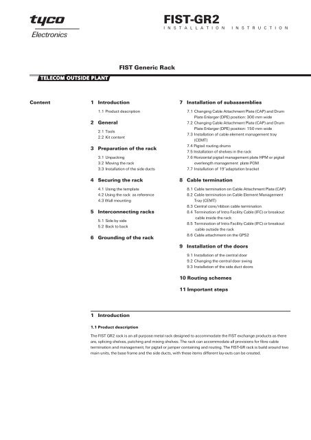
<strong>FIST</strong>-<strong>GR2</strong>I N S T A L L A T I O N I N S T R U C T I O N<strong>FIST</strong> Generic RackContent1 Introduction1.1 Product description2 General2.1 Tools2.2 Kit content3 Preparation of the rack3.1 Unpacking3.2 Moving the rack3.3 Installation of the side ducts4 Securing the rack4.1 Using the template4.2 Using the rack as reference4.3 Wall mounting5 Interconnecting racks5.1 Side by side5.2 Back to back6 Grounding of the rack7 Installation of subassemblies7.1 Changing Cable Attachment Plate (CAP) and DrumPlate Enlarger (DPE) position: 300 mm wide7.2 Changing Cable Attachment Plate (CAP) and DrumPlate Enlarger (DPE) position: 150 mm wide7.3 Installation of cable element management tray(CEMT)7.4 Pigtail routing drums7.5 Installation of shelves in the rack7.6 Horizontal pigtail management plate HPM or pigtailoverlength management plate POM7.7 Installation of 19”adaptation bracket8 Cable termination8.1 Cable termination on Cable Attachment Plate (CAP)8.2 Cable termination on Cable Element ManagementTray (CEMT)8.3 Central core/ribbon cable termination8.4 Termination of Intra Facility Cable (IFC) or breakoutcable inside the rack8.5 Termination of Intra Facility Cable (IFC) or breakoutcable outside the rack8.6 Cable attachment on the GPS29 Installation of the doors9.1 Installation of the central door9.2 Changing the central door swing9.3 Installation of the side duct doors10 Routing schemes11 Important steps1 Introduction1.1 Product descriptionThe <strong>FIST</strong> <strong>GR2</strong> rack is an all purpose metal rack designed to accommodate the <strong>FIST</strong> exchange products as thereare, splicing shelves, patching and mixing shelves. The rack can accommodate all provisions for fibre cabletermination and management, for pigtail or jumper containing and routing. The <strong>FIST</strong>-GR rack is build around twomain units, the base frame and the side ducts, with these items different lay-outs can be created.
2 General2.1 Tools• Standard installer tools as- drill- wrench 8, 13 mm- Philips screwdriver- flat screwdriver 5.5 mm- drive/socket 6, 7 and 8 mm• Allen key for back mounting of shelves FACC-ALLEN-KEY-5-350• For installation of cage nuts in rack FACC-CAGE-NUT-TOOL3 Preparation of the rack3.1 UnpackingSee unpacking leaflet outside of the box.3.2 Moving the rackMoving the rack in horizontal position is possible by sliding the rackwith two people, only using the side supports. Never use the pigtaildrums to lift or move the rack.2.2 Kit content3.3 Installation of a side duct(in case it is not pre installed)3.3.1 Remove the pigtail duct from the base rack and remove thepigtail ducts from the side duct.2.2.1 Depending on the network and exchange design the kitcontent of the rack maybe different. Racks can also obtained withsome of the components pre-assembled in it.The minimum content will be• the base frame including the mounting profiles• adjustable levelling feet• bottom base duct• grounding facility• wall connection kit• installation instruction, unpacking leaflet and template.Optional: side duct including• drum plate enlarger DPE• cable attachment plate CAP• cable securing clamps• cable strength member terminations UCT• doorNote: Supplementary accessories needed for a specific configurationof the rack can be selected from the <strong>GR2</strong> ordering guide.3.3.2 Release all the bolts of the side duct for 5mm (never removethem completely).2
4 Securing the rack4.1 Using the template4.1.1 Place the template against the wall or in the position that therack have to be placed and mark the 4 securing points of the base.In case of special cable floor, mark also the positions where the cablescan be fed through the floor. Cut out the cable entry hole in the floor.4.2 Using the rack as reference3.3.3 Lift the side duct, keep it parallel to the central part and slide itdown.4.2.1 Move the rack in place and mark the floor securing points inthe openings of the adjustable feet of the base rack.3.3.4 Tighten the screws on top and bottom inside the side duct(wrench nr. 8).3.3.5 Tighten the screws using wrench nr 13..4.2.2 If needed remove in the bottom or/and top cable entry coverplates- in the base rack by knocking out the plates in the corners- in the side ducts by removing the covers and plastic plugs.4.2.3 Drill the holes in the floor and install the selected plugsdepending on the floor surface.3
5 Interconnecting racks5.1 Side by side4.2.4 Put the rack back in place and level it by turning the adjustablefeet. Tighten the screws through the adjustable feet into thepreinstalled plugs in the floor.5.1.1 Remove the grounding wire installed on the side panel beforeremoving the panel.4.2.5 Re-install the pigtail duct and bend controlls of the base andthe pigtail duct of the side ducts in the rack.Note: The rack is not a stand alone version and must be additionalsecured to a wall, ceiling or back-to-back with another rack.4.3 Wall mounting5.1.2 Remove the side panel(s) from the installed side duct(s).4.3.1 Install the wall-mounting bracket on the top of the rack. Markthe securing slot to the wall and drill a hole for the securing plug andattach the rack to the wall.4
5.1.3 Remove the side duct support bracket.5.1.6 Use the template or the rack itself to mark the securingpositions of the second rack on the floor and drill the holes in the floor.Install the selected plugs depending on the floor surface.5.1.4 Remove the cage nuts of the panel securing points. Don’t usethe cage-nut tool.5.1.7 Hook in the additional rack and level it by turning theadjustable feet. Tighten the screws through the adjustable feet to thepreinstalled plugs in the floor.5.2 Back to back5.1.5 Install on the top and bottom of the side panel a side toside (STS) attachment plate. If necessary remove the pigtail exit plateon the top to have better access.5.2.1 In case of a rack with back panel, remove the grounding wireinstalled on the back panel before removing it.5
5.2.4 Position the second rack back to back and secure the bottomwith the bolts in the spacers and secure the top with the metalconnection strip.6 Grounding of the rack5.2.2 In case of a rack with back panel remove the back panel fromthe rack.6.1 Interconnect the grounding wires of the base rack to the sideducts.5.2.3 Install on the two bottom locations the spacers on the outsideof the rack. Mark the securing positions of the second rack on the floorby positioning the second rack against the pre-installed spacers of thefirst rack. Remove the rack and drill the holes for the securing plugs.6.2 Install the local approved grounding cable to the vertical groundingbar of the base rack (top or bottom).6
7 Installation of subassemblies7.1 Changing Cable Attachment Plate (CAP) and DrumPlate Enlarger (DPE) positions in side ducts: 300 mm wideOn each side duct a cable attachment plate CAP or drum plate enlargerDPE can be installed on top or bottom depending on the rackconfiguration.7.1.1 Remove the installed DPE by removing the nuts. Use drivesocket 7.7.1.3 Use the long (1) and the short (2) spacers and mount them asshown. First remove the 4 M4 nuts in position 1.7.1.2 Remove the screws of the CAP and slide it out of its position.7.1.4 Install the CAP as shown. Note the correct orientation of the“T”-shaped holes for top and bottom.7
Drumplate7.1.6 In case of cable installation behind the drumplate (see 7.1.5):don’t use a spacer at the top and use 1 nut (M4) as a spacer at thebottom (1).7.1.5 Routing diagram: cable behind the drumplate87.1.7 Mount the plate as shown (could be in the left or the rightside duct, always in the top position). Note the correct orientation ofthe “T”-shaped holes for top and bottom!!
7.2 Changing cable attachment plate (CAP) and DrumPlate Enlarger (DPE) positions in the side duct: 150 mm wide7.2.3 Mount the 3 spacers as shown.7.2.1 Remove the installed DPE by removing the nuts. Use drivesocket 7.7.2.2 Remove the screws of the CAP and slide it out of its position.7.2.4 Install the CAP. Note the correct orientation of the “T”-shapedholes for top and bottom!!9
7.3 Installation of cable element management tray (CEMT)7.3.1 Install the cage nuts for the CEMT on the correct positions ofthe rack mounting profile (see table for determination of the position inthe rack).RackCEMT topsize position (ETSI shelves) 19” shelves1800 mm 56 552200 mm 72 712600 mm 88 877.2.5 In case of cable installation behind the drumplate: don’t useany spacers.7.3.2 Install the CEMT with four screws in the rack.7.3.3 The direction of the plate can be changed.7.2.6 Mount the plate as shown. Note the correct orientation of the“T”-shaped holes for top and bottom!!10
7.4 Pigtail routing drums7.7 Installation of 19”adaptation bracketThe position of the drums can be changed depending on the routingscheme and configuration of the rack. See general routing schemes in#10 or specific scheme depending on the application suppliedseparately.7.4.1 Remove the central bolt inside the drum with the special Allenkey. Make sure that the positioning point of the drums are properlyinserted in the drum plate during installation of a drum.7.5 Installation of shelves in the rack7.7.1 If 19”shelves have to be installed, adaptation brackets to fitthem, are needed.ExamplesTop: 19” shelf with asymmetrical bracketsMiddle: 19” shelf with symmetrical bracketsBottom: ETSI shelf8 Cable termination8.1 Cable termination on a CAP8.1.1 Remove the outer cable jacket of the cable, see table forspecific length depending on the rack size.<strong>FIST</strong> rack size<strong>FIST</strong>-<strong>GR2</strong>-1 (1800 mm)<strong>FIST</strong>-<strong>GR2</strong>-2 (2200 mm)<strong>FIST</strong>-<strong>GR2</strong>-3 (2600 mm)Minimum cable jacket stripping length6000 mm6500 mm7000 mm7.5.1 Place the cage nuts in the vertical frame on the position of theshelves, count the securing positions, 5 units for a shelf or POM, 7 unitsfor a HPM.8.1.2 Cut the strength member leaving 75 mm from the cable cut.7.5.2 Start installing the shelves from the bottom upwards so thefirst installed shelf will support the next one.7.6 Horizontal pigtail management plate HPM or pigtailoverlength management plate POM7.6.1 Install the HPM or POM on the correct position depending onthe rack configuration. The installation is identical to an installation of asplicing or patching shelf see point 7.5.8.1.3 Install the strength member connector onto the strengthmember (1). Mount the plastic clip on the C-profile (2).11
8.1.6 Make a slit in one end of the flex tube and slide the tube overthe fiber tubes up to the cable jacket.8.1.4 Install the cable clamp over the cable in the C profile. Fastenthe screw hand-tight (to avoid optical losses).8.1.7 Secure the flex tube with tie wraps to the drum plate.8.1.5 Two cables can be clamped on top of each other with a doublecable clamp, using an insert in the cable clamp (1). Install a spacerbetween the first and the second strength member connector (2).Triple cable clamps can be used too.8.1.8 Mark the tubes and route them through the flex tubes up tothe shelves.12
8.1.11 Table with CAP capacities for rigid cableCAP 150 capacity (in cable qty)Single clamps Double clamps (*) Triple clamps (*)Cable Ø range12-16 mm 5 cables 10 cables 15 cables16-22 mm 3 cables 6 cables 9 cables22-28 mm 3 cables 6 cables 9 cables28-34 mm 2 cables 4 cables 6 cables**8.1.9 The total number of loose tubes of a cable can be divided inseveral flextubes and routed to different shelves depending on thecable capacity and the network lay-out. Splitting can be done on theside ducts or on the CEMT when available .(*) In case double (or triple) clamps are used for less than 2 (or 3)cables, use a piece of dummy cable or a rod so that all cable positionsof the clamp are filled.** Not possible in rack bottom, in conflict with pigtail duct.CAP 300 capacity (in cable qty)Single clamps Double clamps (*) Triple clamps (*)Cable Ø range12-16 mm 11 cables 22 cables 33 cables16-22 mm 9 cables 18 cables 27 cables22-28 mm 7 cables 14 cables 21 cables28-34 mm 6 cables 12 cables 18 cables**(*) In case double (or triple) clamps are used for less than 2 (or 3)cables, use a piece of dummy cable or a rod so that all cable positionsof the clamp are filled.** Not possible in rack bottom, in conflict with pigtail duct.8.2 Cable termination with CEMT8.1.10 Attach the flextube to the shelf (see instruction of shelvesGSS2,GPS2, GMS2).8.2.1 Follow the installation steps 8.1 to install the cable and theflextube on the CEMT.The picture shows 1 cable entering from the bottom and 1 cablecoming from the top behind the drum plate (alternative).13
4150 mm4000 mm2750 mm0101 0101062631364146515661661116217102030405060708091011121314151617181920212223242526272829303132333435363738394041424344454647484950515253545556575859606162636465666768697071727374757676 76777879800203040506070809101112131415161718192021222324252627282930313233343536373839404142434445464748495051525354555657585960616263646566676869707172737475767778798006111621263136414651566166718.4 Termination of Intra Facility Cable (IFC) or breakoutcable in the rack8.2.2 Mount the cover on the CEMT.8.3 Central core/ribbon cable termination8.3.1 Install the mounting bracket (part of <strong>FIST</strong>-CTB100) for thecable attachment plate in a position as close as possible to the shelfand continue the installation as described in the instruction of GSS2 orGPS2.8.4.1 Cable termination can be done inside the rack, in either cornerof the rack. Additional CAP’s can be mounted on top of each otherusing spacers. Cable jackets are secured using tie-wraps.2 cables can be mounted on top of each other using a spacer for thestrength member.Overview of cable length for BREAKOUT and INTRA-FACILITY cableoverview of cable length for BREAKOUT cable150 mm123452900 mm67123458.3.2 The cable bracket can be mounted on the CEMT.noconnectorspreconnectorised678.4.2 Cable and cable jacket stripping lengths for a 2.2 m high rackare indicated for these specific configurations. Lengths are measuredfrom top or bottom edge of the rack (same length).14
8.4.3 Table with CAP capacities for IFC or breakout cable inside the rackCAP 150 capacity (in cable qty)In rack TOP or BOTTOMIn rack TOP only1 CAP plate 2 CAP plates 3 CAP platesCable Ø range≤ 18 mm 12 cables 20 cables 28 cables (*)18-22 mm 10 cables 18 cables 26 cables(*) 3 CAP plates is impossible in the rack bottom because it conflictswith the pigtail duct. In case the pigtail duct is not used, it can beremoved and then 3 CAP plates can be mounted in the rack bottom aswell.CAP 300 capacity (in cable qty)Cable Ø rangeIn rack TOP or BOTTOMIn rack TOP only1 CAP plate 2 CAP plates 3 CAP plates8.5.2 Mount the cables as shown. Cable jackets are secured usingtiewraps. 2 cables can be mounted on top of each other using a spacerfor the strength member.≤ 22 mm 24 cables 44 cables 64 cables (*)(*) 3 CAP plates is impossible in the rack bottom because it conflictswith the pigtail duct. In case the pigtail duct is not used, it can beremoved and then 3 CAP plates can be mounted in the rack bottom aswell.8.5 Termination of Intra Facility Cable (IFC) or breakoutcable outside the rack8.5.3 Mount additional plates as shown.8.5.1 Cable termination can be done outside the rack, on top of theside duct using an extra kit. Mount the bracket as shown.Note the correct orientation of the plate!!15
9 Installation of the doors9.1 Installation of the central door8.5.4 Mount the protective cover as shown.8.5.5 Table with CAP capacities for IFC or breakout cable outside the rackCable Ø range 150 mm side duct 300 mm side duct9.1.1 Place the bottom securing pin in the rack base. Pull the topsecuring pin down and position the door, release the door pin till itpasses through the turning point.≤ 18 mm 36 cables 104 cables18-22 mm 34 cables 104 cables8.6 Cable attachment on the GPS29.1.2 Install the door opening limitation bar by hooking the pin in themiddle of the guiding slot of the base rack.8.6.1 Guide the cable up to the selected shelf and use tie wraps tofix it onto the side termination plate.Follow the installation instruction of the GPS2 for installation androuting of the cable and flex tube to the shelf.9.1.3 Install the grounding connector to the door.16
9.2 Changing the central door swing9.2.1 Remove door stop on the right top of the base rack and place itin the same position on the left side of the rack.9.2.5 Remove the screws of the door handle and lock.9.2.2 Remove the plastic support plate from the right bottom side ofthe rack and replace it on the left side of the rack.9.2.6 Remove the spring clips of connection between the lockingbars and the door lock.9.2.3 Remove door limitation bar and the grounding connection ofthe door and replace it on the other side of the door.9.2.7 Turn the door lock in the opposite direction (upside down andfront to back).9.2.4 Remove the door handle by removing the central bolt in thedoor lock.9.2.8 Re install the door lock and fix it with the screws.9.2.9 Re install the locking bars with the spring clips to the doorhandle.9.2.10 Re install the door handle with the central bolt.17
9.3 Installation of the side duct doors9.3.1 Slide the top door pin in the turning hole till it is possible toinsert the bottom pin into the hole on the bottom of the rack.9.3.2 Install the provided grounding wire from the base to the door.18
10 Routing schemes10.1 CrossconnectCROSSCONNECT SINGLE CIRCUIT288 X 288 FIBERSCrossconnect jumper 5 m19
10.2 InterconnectINTERCONNECT SINGLE CIRCUIT576 FIBERS20
10.3 Multiple rack full cross connectCROSSCONNECT - SINGLE ELEMENT - 1008 X 1008 FIBERSCrossconnectjumper 7 m21
10.4 Jumper lengths7 meter length for connections to the adjacent racks left and right and back to back.8.2 meter length for jumpers going through one intermediate rack.9.5 meter of jumper needed when connecting two racks with two racks in between.11 Important steps• Always level the rack.• Secure the rack on floor and wall or ceiling.• Respect the positions of the drums.• Bundle pigtails with velcro tape.• Respect bending radius of 30 mm.• Install always the grounding wires.• Never install a shelve on position OO.This will create problems to close the central door.• Respect correct orientation of the cable attachment plates.22
Tyco Electronics Raychem NVTelecom Outside PlantDiestsesteenweg 692B-3010 Kessel-Lo, BelgiumTel.: 32-16-351 011Fax: 32-16-351 697www.tycoelectronics.comwww.telecomosp.comTyco is a trademark. Velcro is a trademark of Velcro Industries B.V.The information given herein, including drawings, illustrations and schematic which are intended for illustration purposes only, isbelieved to be reliable. However, Tyco Electronics makes no warranties as to its accuracy or completeness and disclaims anyliability in connection with its use. Tyco Electronics’ obligations shall only be as set forth in Tyco Electronics’ Standard Terms andConditions of Sale for this product and in no case will Tyco Electronics be liable for any incidental, indirect or consequentialdamages arising out of the sale, resale, use or misuse of the product. Users of Tyco Electronics products should make their ownevaluation to determine the suitability of each such product for the specific application.TC 605/IP/3 02/02