Operation and maintenance instructions (NC) - LK Systems AB
Operation and maintenance instructions (NC) - LK Systems AB
Operation and maintenance instructions (NC) - LK Systems AB
- No tags were found...

You also want an ePaper? Increase the reach of your titles
YUMPU automatically turns print PDFs into web optimized ePapers that Google loves.
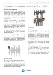
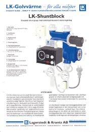
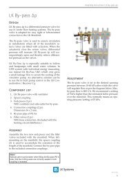
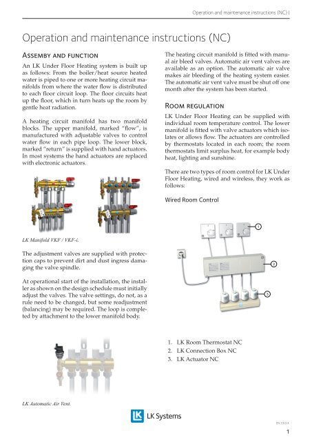
<strong>Operation</strong> <strong>and</strong> <strong>maintenance</strong> <strong>instructions</strong> (<strong>NC</strong>) |<strong>Operation</strong> <strong>and</strong> <strong>maintenance</strong> <strong>instructions</strong> (<strong>NC</strong>)Assemby <strong>and</strong> functionAn <strong>LK</strong> Under Floor Heating system is built upas follows: From the boiler/heat source heatedwater is piped to one or more heating circuit manifoldsfrom where the water flow is distributedto each floor circuit loop. The floor circuits heatup the floor, which in turn heats up the room bygentle heat radiation.A heating circuit manifold has two manifoldblocks. The upper manifold, marked “flow”, ismanufactured with adjustable valves to controlwater flow in each pipe loop. The lower block,marked ”return” is supplied with h<strong>and</strong> actuators.In most systems the h<strong>and</strong> actuators are replacedwith electronic actuators.The heating circuit manifold is fitted with manualair bleed valves. Automatic air vent valves areavailable as an option. The automatic air valvemakes air bleeding of the heating system easier.The automatic air vent valve must be shut off onemonth after the system has been started.Room regulation<strong>LK</strong> Under Floor Heating can be supplied withindividual room temperature control. The lowermanifold is fitted with valve actuators which isolatesor allows flow. The actuators are controlledby thermostats located in each room; the roomthermostats limit surplus heat, for example bodyheat, lighting <strong>and</strong> sunshine.There are two types of room control for <strong>LK</strong> UnderFloor Heating, wired <strong>and</strong> wireless, they work asfollows:Wired Room Control1<strong>LK</strong> Manifold VKF / VKF-i.The adjustment valves are supplied with protectioncaps to prevent dirt <strong>and</strong> dust ingress damagingthe valve spindle.2At operational start of the installation, the installeras shown on the design schedule must initiallyadjust the valves. The valve settings, do not, as arule need to be changed, but some readjustment(balancing) may be required. The loop is completedby attachment to the lower manifold body.31. <strong>LK</strong> Room Thermostat <strong>NC</strong>2. <strong>LK</strong> Connection Box <strong>NC</strong>3. <strong>LK</strong> Actuator <strong>NC</strong><strong>LK</strong> Automatic Air Vent.EN.33.D.4.1
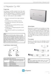
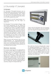
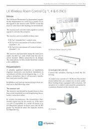
<strong>Operation</strong> <strong>and</strong> <strong>maintenance</strong> <strong>instructions</strong> (<strong>NC</strong>) |Room thermostats <strong>and</strong> actuators are connectedelectrically via an <strong>LK</strong> Connection Box <strong>NC</strong>.• A lit diode on the <strong>LK</strong> Room Thermostatindicates that it is ”calling” for heat <strong>and</strong>the actuator opens the valve on the heatingcircuit manifold.• An unlit diode indicates that the actuatorshuts down <strong>and</strong> circulation stops in the underfloor heating circuit.• If the installation is connected via the <strong>LK</strong>Connection Box <strong>NC</strong>, the diodes on the boxindicate when the actuator opens <strong>and</strong> closes(lit diode = actuator opens).• The actuators bonnet indicates whether thevalve is open or closed. If the bonnet is up<strong>and</strong> the blue marker ring is visible, the valveis open, the correct position when a roomthermostat is calling for heat <strong>and</strong> the connectionbox diode is lit. The cycle time forthe actuator is approximately 2 x 5 minutes[open to close, close to open].• Room thermostats <strong>and</strong> actuators are closedwhen there is no power (current). (<strong>NC</strong>) 24 VAC.• To operate the room control, the connectionbox has an integral transformer 230/24 VAC, 40 VA. The transformer is equippedwith a 200mA fuse on the primary side. Priorto changing the fuse, ensure that the voltageto the connection box is switched off.NOTE:This fuse MUST NOT be part of anyswitched system <strong>and</strong> should be live continuously.Wireless room control1. <strong>LK</strong> Room Thermostat Cq-n2. <strong>LK</strong> Reciever Cq 83. <strong>LK</strong> Actuator <strong>NC</strong>The room thermostats send radio signals to thereceiver, which are then converted into controlsignals for each actuator. Receivers are availablewith two different channel ranges, 1 <strong>and</strong> 8, dependingon how many room thermostats needprogramming. Channel 7 can be used to controlthe installations’´pump. Provided a thermostathas not been programmed to chanel 7 or 8.Receiver Cq 8• A lit diode on the receiver for Cq 8 indicatesthat it is calling for heat, <strong>and</strong> the actuatoropens the valve on the heating circuit manifold.• An unlit diode indicates that the pump isshutting down <strong>and</strong> circulation is stopping inthe under floor heating circuit.• The actuators bonnet indicates whether thevalve is open or closed. If the bonnet is up<strong>and</strong> the blue marker ring is visible, the valveis open, the correct position when a roomthermostat is calling for heat <strong>and</strong> the receivers’diode is lit. The cycle time for the actuatoris approximately 2 x 5 minutes [open toclose, close to open].• The actuator is normally closed (<strong>NC</strong>) 24VAC.231EN.33.D.4.2
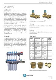
<strong>Operation</strong> <strong>and</strong> <strong>maintenance</strong> <strong>instructions</strong> (<strong>NC</strong>) |Receiver Cq 1• An lit diode on the receiver for Cq 1 indicatesthat it is calling for heat, so the actuatoropens the valve on the heating circuit manifold.• A unlit diode indicates that the manifoldactuator is closing <strong>and</strong> circulation is stoppingin the under floor heating circuit.• The actuators bonnet indicates whether thevalve is open or closed. If the bonnet is up<strong>and</strong> the blue marker ring is visible, the valveis open, the correct position when a roomthermostat is calling for heat <strong>and</strong> the receivers’diode is lit. The cycle time for the actuatoris approximately 2 x 5 minutes [open toclose, close to open].• The actuator is normally closed (<strong>NC</strong>) 24VAC.Alarms/interruptions• A flashing diode ore a flashing diode witha sound signal on Cq 1 <strong>and</strong> 8 indicates analarm/interruption. For more information,please refer to the assembly <strong>instructions</strong> for<strong>LK</strong> Wireless Room Control Cq (<strong>NC</strong>).• A flashing diode on the Room thermostatindicates that the battery needs to be replaced.Room thermostats are equipped with 2st<strong>and</strong>ard batteries, alkaline 1.5 Volt (LR03).<strong>LK</strong> Repeater Cq HWThe <strong>LK</strong> Repeater Cq HW is used to increase thetransmitting distance between <strong>LK</strong> Room ThermostatCq <strong>and</strong> <strong>LK</strong> Receiving Unit Cq 8. The Repeateris also used when it may be necessary to improvethe quality of transmission, e.g. when affected byexternal sources of interference. Place the repeaterat an appropriate distance from the transmitter/room thermostat. The repeater is made for fixedinstallation on the wall <strong>and</strong> is connected to 230 V.The Repeater will work automatically when poweris connected. For more information, see seperate<strong>instructions</strong> for <strong>LK</strong> Repeater Cq HW.To work correctly, the receiver Cq 8 must be connectedvia transformer to 230V AC.To work correctly, the receiver Cq 1 must be connectedto 230 V. Control output are operated via aseparate transformer 230 V/24 VFeed temperature & weather compensationAn outdoor temperature compensated (weathercompensation) feed temperature is required for acomfortable, even indoor climate. The curve slopeof the regulation equipment must be adaptedto the calculated feed temperature of each underfloor heating installation. To set the curve slopeof the regulation equipment of the heat source,follow the manufacturer’s <strong>instructions</strong>.EN.33.D.4.3
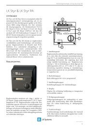
<strong>Operation</strong> <strong>and</strong> <strong>maintenance</strong> <strong>instructions</strong> (<strong>NC</strong>) |Shunt group<strong>LK</strong> Shunt.<strong>LK</strong> Manifold Shunt CS.<strong>LK</strong> Under Floor Heating is a low-temperaturesystem using approx. 20 to 35ºC lower flow temperaturesthan radiators. When using ”divided”systems, for example under floor heating combinedwith radiators, the shunt group is requiredto achieve lower flow temperatures for the underfloor heating by controlled mixing of primaryheated water with the return secondary water.The shunt group can be set manually to a fixedmixing ratio, ensuring that the under floor heatingsystem constantly maintains a set lower feedtemperature than the radiator system. Pleasenote that the feed temperature is still outdoorcompensated,as the regulating equipment forthe heat source regulates the temperature to theradiators <strong>and</strong> thus also, indirectly, the under floorheating system.The shunt group can be supplemented by automaticregulating equipment. This is done whenthe shunt group is connected to a system that isnot pre-shunted, i.e. maintains a constant temperature.<strong>Operation</strong>A correctly assembled <strong>and</strong> adjusted <strong>LK</strong> UnderFloor Heating system can be considered virtually<strong>maintenance</strong> free.However, the following checks must be performed:• Keep an operating log <strong>and</strong> make a note ofinspection days, observations <strong>and</strong> any action.• Inspect the heating circuit manifold regularly<strong>and</strong> check that there are no leaks. Even dripsmust be remedied immediately.• Operating pressure <strong>and</strong> feed temperaturemust be checked during operation.• Any action affecting floor joists is onlypermitted in consultation with the project’sresident engineer or the person responsiblefor quality control.• All isolation valves in the under floor heatingsystem should be tested once or twice a year.As a supplement to these operation <strong>and</strong> <strong>maintenance</strong><strong>instructions</strong>, assembly <strong>instructions</strong> forthe products are enclosed with each suppliedproduct. The assembly <strong>instructions</strong> provide additionalinformation on the connections, settings<strong>and</strong> programming, etc. required for the productin question.If any of the <strong>instructions</strong> are missing, you can orderor download them from our website: www.lksystems.co.ukMaterial recoveryWaste from scrapping <strong>and</strong> dismantling can beh<strong>and</strong>led by normal building refuse management.For additional information, please refer to theenvironmental product declaration for each product.These can be obtained from <strong>LK</strong> <strong>Systems</strong> Ltdor downloaded from our website: www.lksystems.co.ukNo parts of the system are classified as hazardouswaste. <strong>LK</strong> does not accept packaging material returns.EN.33.D.4.4