Duct Temperature Transmitters - BAPI
Duct Temperature Transmitters - BAPI
Duct Temperature Transmitters - BAPI

You also want an ePaper? Increase the reach of your titles
YUMPU automatically turns print PDFs into web optimized ePapers that Google loves.
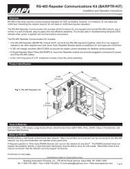
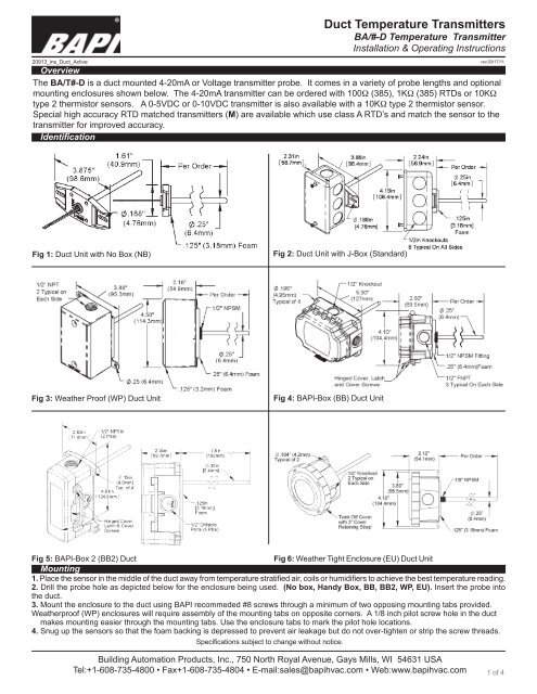
20913_ins_<strong>Duct</strong>_Active<strong>Duct</strong> <strong>Temperature</strong> <strong>Transmitters</strong>BA/#-D <strong>Temperature</strong> TransmitterInstallation & Operating InstructionsOverviewThe BA/T#-D is a duct mounted 4-20mA or Voltage transmitter probe. It comes in a variety of probe lengths and optionalmounting enclosures shown below. The 4-20mA transmitter can be ordered with 100W (385), 1KW (385) RTDs or 10KWtype 2 thermistor sensors. A 0-5VDC or 0-10VDC transmitter is also available with a 10KW type 2 thermistor sensor.Special high accuracy RTD matched transmitters (M) are available which use class A RTD’s and match the sensor to thetransmitter for improved accuracy.Identificationrev.03/17/11Fig 1: <strong>Duct</strong> Unit with No Box (NB)Fig 2: <strong>Duct</strong> Unit with J-Box (Standard)Fig 3: Weather Proof (WP) <strong>Duct</strong> UnitFig 4: <strong>BAPI</strong>-Box (BB) <strong>Duct</strong> UnitFig 5: <strong>BAPI</strong>-Box 2 (BB2) <strong>Duct</strong>Fig 6: Weather Tight Enclosure (EU) <strong>Duct</strong> UnitMounting1. Place the sensor in the middle of the duct away from temperature stratified air, coils or humidifiers to achieve the best temperature reading.2. Drill the probe hole as depicted below for the enclosure being used. (No box, Handy Box, BB, BB2, WP, EU). Insert the probe intothe duct.3. Mount the enclosure to the duct using <strong>BAPI</strong> recommeded #8 screws through a minimum of two opposing mounting tabs provided.Weatherproof (WP) enclosures will require assembly of the mounting tabs on opposite corners. A 1/8 inch pilot screw hole in the ductmakes mounting easier through the mounting tabs. Use the enclosure tabs to mark the pilot hole locations.4. Snug up the sensors so that the foam backing is depressed to prevent air leakage but do not over-tighten or strip the screw threads.Specifications subject to change without notice.Building Automation Products, Inc., 750 North Royal Avenue, Gays Mills, WI 54631 USATel:+1-608-735-4800 • Fax+1-608-735-4804 • E-mail:sales@bapihvac.com • Web:www.bapihvac.com1 of 4
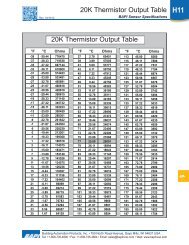
20913_ins_<strong>Duct</strong>_ActiveMounting Continued<strong>Duct</strong> <strong>Temperature</strong> <strong>Transmitters</strong>BA/#-D <strong>Temperature</strong> TransmitterInstallation & Operating Instructionsrev.03/17/11Mounting Notes:Note 1Be sure not to drill into the weatherproofenclosures (BB, BB2, WP,EU,EUO) whichwill violate the NEMA and/or the IP rating.Note 2Be sure to use caulk or Teflon tape on allthreaded openings to maintain the appropriateNEMA or IP rating for your application.Fig 7-A: Junction Box or No-Box NBMounting HolesFig 8-A: BB2 Mounting HolesNote 3Conduit entry for outdoor or wet applicationsshould be from the bottom of the enclosure.Fig 7-B: Junction Box or No-Box NB<strong>Duct</strong> InstallationFig 8-B: BB2 <strong>Duct</strong> InstallationFig 9-A: <strong>BAPI</strong>-Box BB EnclosureMounting Holes Rotate 90° forHorizontal MountingFig 10- A: EU or EUO Enclosure Mounting HolesFig 11-A: Weatherproof Box WPMounting HolesFig 9-B: <strong>BAPI</strong>-Box BB <strong>Duct</strong> InstallationFig 10-B: EU or EUO Enclosure<strong>Duct</strong> InstallationSpecifications subject to change without notice.Fig 11-B: Weatherproof Box WP<strong>Duct</strong> installationBuilding Automation Products, Inc., 750 North Royal Avenue, Gays Mills, WI 54631 USATel:+1-608-735-4800 • Fax+1-608-735-4804 • E-mail:sales@bapihvac.com • Web:www.bapihvac.com2 of 4
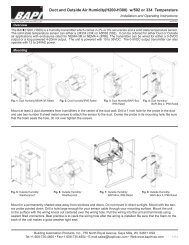
20913_ins_<strong>Duct</strong>_ActiveWiring & Termination<strong>Duct</strong> <strong>Temperature</strong> <strong>Transmitters</strong>BA/#-D <strong>Temperature</strong> TransmitterInstallation & Operating Instructionsrev.03/17/11<strong>BAPI</strong> recommends using twisted pair of at least 22AWG and sealant filled connectors for all wire connections. Larger gauge wire maybe required for long runs. All wiring must comply with the National Electric Code (NEC) and local codes. Do NOT run this device’s wiringin the same conduit as high or low voltage AC power wiring.<strong>BAPI</strong>’s tests show that inaccurate signal levels are possible when AC power wiring is present in the same conduit as the sensor wires.Fig 15: Typical RTD 4-20 mA Transmitter W/Flying LeadsFig 16:Typical RTD 4-20mA Transmitter W/TerminalsFig 17: Typical Thermistor 4-20mA TransmitterDiagnosticsProblems:•Unit will not operate4-20mA <strong>Temperature</strong> EquationT = TLow + (A -4) x (TSpan)16T = <strong>Temperature</strong> at sensorTLow = Low temperature of spanTHigh = High temperature of spanTSpan= THigh - TLowA = Ammeter reading in mA•The reading is incorrect in the controllerVoltage <strong>Temperature</strong> EquationT = TLow + (V x TSpan)VSpanT = <strong>Temperature</strong> at sensorTLow = Low temperature of spanTHigh = High temperature of spanTSpan = THigh - TLowVLow = Low transmitter voltageusually=(0, 1 or 2v)VHigh = High transmitter voltageusually=(5 or 10v)VSpan =VHigh - VLowV =Signal reading in voltsFig 18:Typical Thermistor Voltage TransmitterPossible Solutions:- Measure the power supply voltage by placing a voltmeter acrossthe transmitter’s (+) and (-) terminals.The voltage reading shouldbe between 7 to 40 VDC.- Check if the RTD wires are physically open or shorted togetherand are terminated to the transmitter.- Measure the physical temperature at the temperature sensor’slocation using an accurate temperature standard. Disconnect thetemperature sensor wires and measure the temperature sensor’s resistancewith an ohmmeter. Compare the temperature sensor’s resistanceto the appropriate temperature sensor table on the <strong>BAPI</strong> web site.- Determine if the input is set up correctly in the controllersand BAS software.- For a 4-20mA current transmitter measure the transmitter currentby placing an ammeter in series with the controller input. Thecurrent should read according to the equation shown at left.- For a voltage transmitter, measure the signal with a volt meter(Green to Black). The signal should read according to the voltageequation shown at left.Specifications subject to change without notice.Building Automation Products, Inc., 750 North Royal Avenue, Gays Mills, WI 54631 USATel:+1-608-735-4800 • Fax+1-608-735-4804 • E-mail:sales@bapihvac.com • Web:www.bapihvac.com3 of 4
20913_ins_<strong>Duct</strong>_ActiveSpecificationsRTD TransmitterPower Required 7 to 40VDCTransmitter Output 4-20mA, 850W@24VDCOutput wiring 2 wire loopOutput Limits