InfiniiVision 4000 X-Series Oscilloscopes
InfiniiVision 4000 X-Series Oscilloscopes
InfiniiVision 4000 X-Series Oscilloscopes

Create successful ePaper yourself
Turn your PDF publications into a flip-book with our unique Google optimized e-Paper software.
<strong>InfiniiVision</strong> <strong>4000</strong> X-<strong>Series</strong><strong>Oscilloscopes</strong>Data sheetOscilloscope Experience Redefined:Experience the speed, usability and integration
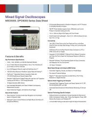
Oscilloscope Experience Redefined: Experience the speed, usability, and integrationImagine an oscilloscope that sees everything, triggers onanything, has the ease-of-use of a tablet device…and growswith your projects.The <strong>4000</strong> X-<strong>Series</strong> oscilloscopes are engineered for nextgenerationperformance, delivering waveform update rates20 times faster than the competition to display the mostsignal detail. An industry-leading 12.1-inch capacitive touchscreen with innovative hardware-based InfiniiScan Zonetouch triggering provides the most intuitive interface to getyou answers faster. The <strong>4000</strong> X-<strong>Series</strong> provides maximuminvestment protection with fully upgradable 5-instrumentsin-1.Experience the SpeedAnomalies and elusive events are the toughest to debug.The <strong>4000</strong> X-<strong>Series</strong> oscilloscope redefines your debuggingexperience with MegaZoom IV smart memory technology.The industry-leading 1-million-waveforms-per-second updaterate, means you see more of your signal behavior and canfeel more confident in your design.<strong>4000</strong> X-<strong>Series</strong> - Oscilloscope experience redefined:Key features:• Experience the speed:· One million waveforms per secondupdate rate· MegaZoom IV smart memory technology· Standard segmented memory• Experience the usability:· Industry’s first capacitive touch screen· Industry’s largest 12-inch display· InfiniiScan Zone touch trigger• Experience the integration:· Industry’s first 5 instruments in 1· Industry’s first fully upgradable includingbandwidth to 1.5 GHz· Industry’s leading application solutionsExperience the UsabilityYou may be surprised just how easy it is to use the<strong>InfiniiVision</strong> <strong>4000</strong> X-<strong>Series</strong>. A 12.1-inch capacitive touchscreen − the industry’s largest − works just like your favoritetablet or smart phone, so debugging your devices is fasterthan ever before. Innovative InfiniiScan Zone touch triggeringmakes triggering on anything a snap. Just draw a box aroundsignals of interest and the oscilloscope triggers on them. So,if you can see it, you can trigger on it.Experience the IntegrationThe <strong>4000</strong> X-<strong>Series</strong> further redefines your oscilloscopeexperience by integrating the capabilities of five instrumentsin one: oscilloscope channels, logic channels, digitalvoltmeter (DVM), dual-channel WaveGen function/arbitrarywaveform generator, and serial protocol analyzer includingUSB. All are upgradable, including bandwidth, for theultimate investment protection.Figure 1: MegaZoom IV smart memory technology enables thespeed, usability, and integration.2
Oscilloscope Experience Redefined: Experience the speed, usability, and integrationOverview of Agilent <strong>InfiniiVision</strong> X-<strong>Series</strong> oscilloscopes<strong>InfiniiVision</strong> <strong>4000</strong> X-<strong>Series</strong> <strong>InfiniiVision</strong> 3000 X-<strong>Series</strong> <strong>InfiniiVision</strong> 2000 X-<strong>Series</strong>Analog channels 2 and 4 2 and 4 2 and 4Bandwidth (upgradable) 200, 350, 500 MHz, 1 GHz, 1.5 GHz 100, 200, 350, 500 MHz, 1 GHz 70, 100, 200 MHzDigital channels 16 (MSO models or upgrade) 16 (MSO models or upgrade) 8 (MSO models or upgrade)Maximum sample rate 5 GSa/s 5 GSa/s (1-GHz models)2 GSa/s4 GSa/s (100-500 MHz models)Maximum memory depth 4 Mpts (standard) 2 Mpts (standard), 4 Mpts (option) 100 kptsWaveform update rate > 1,000,000 waveforms per second > 1,000,000 waveforms per second > 50,000 waveforms per secondDisplay 12.1-inch capacitive touch display 8.5-inch display 8.5-inch displayInfiniiScan Zone touch trigger Standard No NoWaveGen 20-MHz function/ Dual-channel AWG (option) Single-channel AWG (option) Single-channel function (option)arbitrary waveform generatorIntegrated digital voltmeter Yes (option) Yes (option) Yes (option)Search and navigate Yes Yes NoSerial protocol analysis Yes (optional: ARINC 429, CAN, Yes (optional: ARINC 429, CAN NoFlexRay, I 2 C, I 2 S, LIN, MIL-STD-1553,SPI, UART/RS232, USB 2.0)FlexRay, I 2 C, I 2 S, LIN, MIL-STD-1553, SPI, UART/RS232)Segmented memory Standard Yes (option) Yes (option)Mask/limit testing Yes (option) Yes (option) Yes (option)Power analysis Yes (option) Yes (option) NoHDTV analysis Yes (option) Yes (option) NoAdvanced waveform math Standard Yes (option) NoConnectivityStandard USB2.0, LAN, video out (GPIBoption)Standard USB2.0 (LAN/Videooption) (GPIB option)Standard USB2.0 (LAN/Videooption) (GPIB option)Need more memory, bandwidth, or analysis?See the <strong>InfiniiVision</strong> 9000 <strong>Series</strong>• 600 MHz, 1 GHz, 2.5 GHz, 4 GHz• Up to 20 GSa/s• 20 Mpts per channel standard• Up to 1 Gpts optional• 4 channel + 16 digital channel (MSO or upgrade)• Industry’s largest 15-inch touch display• Industry’s only serial protocol viewer with multi-tabviewing• Widest range of applications including serial compliance,jitter analysis and more.Figure 2: <strong>InfiniiVision</strong> 9000 <strong>Series</strong> oscilloscope.See www.agilent.com/find/9000 for details.3
Oscilloscope Experience Redefined:Experience the SpeedOne million waveforms per second update rateIf you can’t see the problem, it is hard to troubleshoot it.With industry-leading one million waveforms per secondupdate rate, the <strong>InfiniiVision</strong> <strong>4000</strong> X-<strong>Series</strong> gives you thehighest probability of capturing random and infrequentevents that you would miss on an oscilloscope with alower waveform update rate.Powered by MegaZoom IV smart memory technology,the <strong>InfiniiVision</strong> <strong>4000</strong> X-<strong>Series</strong> not only lets you seemore waveforms, but it has the uncompromised abilityto find the most difficult problems in your design. Unlikeother oscilloscopes, uncompromised ability means:• Always-fast, responsive operation• No slowdown with logic channels on• No slowdown with protocol decoding on• No slowdown with math functions turned on• No slowdown with measurements turned onFigure 3: The <strong>4000</strong> X-<strong>Series</strong> captures a glitch occurring once ina million waveform cycles.What is waveform update rate andwhy is it important?As oscilloscopes acquire data, processit, and plot it to the screen, there isinevitable “dead time,” or the timeoscilloscopes miss signals completely.In general, the faster the waveformupdate rate, the shorter the dead time.The shorter the dead time, the morelikely an oscilloscope is to captureanomalies and infrequent events.This is why it is critical to select anoscilloscope with a fast waveformupdate rate.Figure 4: Other vendor’s oscilloscope with 50,000 waveforms/second. A long dead timedecreases your chances of capturing infrequent events.Figure 5: <strong>InfiniiVision</strong> <strong>4000</strong> X-<strong>Series</strong> with 1,000,000 waveforms/second. A short deadtime increases your chances of capturing infrequent events.4
Oscilloscope Experience Redefined:Experience the SpeedAgilent achieves this industry-leading waveform updaterate with MegaZoom IV smart memory technologyTraditionally, CPU processing was the major bottleneck foroscilloscope waveform update rate and responsiveness.Typically, the CPU handles interpolations, logic channelplotting, serial bus decoding, measurements and more,and the waveform update rate drops dramatically as thesefeatures are turned on.The <strong>InfiniiVision</strong> <strong>4000</strong> X-<strong>Series</strong> requires minimum supportfrom a CPU, as most core operations are handled by Agilentproprietary technology, the MegaZoom IV smart memoryASIC. MegaZoom includes hardware serial decoders andhardware mask/limit testing capability, plots analog anddigital data directly to the display, supports GUI operation,and integrates additional instruments like the dual-channelWaveGen function/arbitrary waveform generator.Figure 6. The <strong>4000</strong> X-<strong>Series</strong> oscilloscopes’ uncompromised responsiveness, speed and waveform update rate is enabled by theMegaZoom IV, smart memory ASIC. The CPU is not used for core waveform operations.5
Oscilloscope Experience Redefined:Experience the SpeedSegmented memory: A smartand efficient way to capturewaveformsAcquisition memory size is an essentialoscilloscope specification because itdetermines the amount of data youcan capture in a single acquisition.In general, longer memory is better.However, no memory is always longenough to capture all the signalsyou need, especially when capturinginfrequent anomalies, data bursts, ormultiple serial bus packets. Segmentedmemory acquisition lets you selectivelycapture and store important signalactivity without capturing unimportantsignal idle time with the time stampof each segment relative to the firsttrigger event. Segmented memorycomes standard in the<strong>4000</strong> X-<strong>Series</strong>.Figure 7 shows segmented memorysuccessfully capturing 1,000 events in3.27274 seconds. Traditional memoryarchitecture would require 2.7 Gpts ofmemory to accomplish the same result.This memory is not available on anyscope in the market.Figure 7: Segmented memory efficiently manages the memory to capture up to 1,000segments of interest to you, making it an effective ultra-deep memory oscilloscope thatcan easily capture infrequent events and anomalies.Segmented memory + serial decodeSegmented memory works in conjunction with serialprotocol decode. For example, by setting the triggercondition to “CAN serial bus error,” segmented memorycaptures and stores only CAN error packets and stitchestogether each segment for easy viewing. You can quicklycompare time tags to discover time intervals between errors.6Figure 8: Segmented memory being used in conjunction withserial decode resulting in maximum insight into serial bus.
Oscilloscope Experience Redefined:Experience the SpeedMask/limit testing (option)Whether you are performing pass/fail tests to specifiedstandards in manufacturing or testing for infrequent signalanomalies, mask/limit testing can be a valuable productivitytool (DSOX4MASK). The <strong>4000</strong> X-<strong>Series</strong> features powerfulhardware-based mask testing and can perform up to 270,000tests per second. You can select multiple test criteria,including the ability to run tests for a specific number ofacquisitions, a specified time, or until detection of a failure.Figure 9 Mask testing evaluated > 22 M waveforms in just2 minutes.Search and navigationThe parametric and serial bus search and navigation featurecomes standard on the <strong>4000</strong> X-<strong>Series</strong> oscilloscopes. Whenyou are capturing long, complex waveforms using anoscilloscope’s deep acquisition memory, manually scrollingthrough stored waveform data to find specific events ofinterest can be slow and cumbersome. With automaticsearch and navigation capability, you can easily set upspecific search criteria and then quickly navigate to “foundand marked” events. Available search criteria include edges,pulse width (time-qualified), rise/fall times (time-qualified),runt pulses (time- and level-qualified), and serial bus frames,packets, and errors.Figure 10: The <strong>4000</strong> X-<strong>Series</strong> was set up to capture data signalswith various rise time edges. Using the search and navigationcapability, the oscilloscope was able to find, mark (whitetriangles), and quickly navigate to 16 occurrences of “out ofcompliance” rise-time edges.Figure 11: Using the error condition search, the <strong>4000</strong> X-<strong>Series</strong>quickly found 5 places with a missing acknowledgment in an I²Cserial bus. The navigation feature moves between the errors andzooms automatically to show the error packet.7
Oscilloscope Experience Redefined:Experience the UsabilityIndustry’s largest 12.1-inch displayFrom the start of product development, we designed everyaspect of this oscilloscope for a touch interface. Large,easily touchable targets on the industry’s largest 12.1-inch display and capacitive touch screen technology meanoperation is quick and natural, just like your favorite tabletdevices.Capacitive touch screen technologyCapacitive touch screen technology provides enhancedproductivity. Use the alphanumeric pad for quick annotation,place waveforms or cursors in exact positions and dragdocking panels across the screen to see more measurementinformation.The <strong>4000</strong> X-<strong>Series</strong> offers three ways to access key menusand features: touch GUI for those that prefer tablet orsmart phone touch interfaces, front panel keypads for thetraditional oscilloscope users, and Agilent Spark pull downmenu for users who prefer Windows-like operations. The<strong>4000</strong> X-<strong>Series</strong> also offers a “touch off” button and USBmouse and keyboard support.Figure 12. The industry’s largest 12.1-inch display and capacitivetouch screen technology with large, touchable targets.Redefine your remote Web control oscilloscope experience.The <strong>4000</strong> X-<strong>Series</strong> not only supports traditional control via aPC Web browser, but also supports remote control throughpopular tablet devices.Figure 13: See 10 measurements, cursor information, andthe DVM simultaneously by dragging the desired dockingpanel to any open area.8Figure 14: Use the Agilent Spark pull-down menu forWindows-like operation.
Oscilloscope Experience Redefined:Experience the UsabilityInfiniiScan Zone touch triggerOne of the biggest challenges of using an oscilloscope issetting up an advanced trigger to isolate a signal of interest.While advanced triggers are powerful features, InfiniiScanZone touch trigger provides a turnkey trigger solution.You simply observe the signal of interest on the display, anddraw a zone (box) around it. What used to be hours of workcan now take just a few seconds. If you want to move yourzones to another location, just drag them over. The <strong>4000</strong>X-<strong>Series</strong> can be set up to easily trigger on one or two zoneboxes simultaneously with either must intersect or must notintersect conditions.InfiniiScan Zone triggering does not compromise thewaveform update rate; the <strong>4000</strong> X-<strong>Series</strong> will still maintainan ultra-fast 200,000 waveforms per second or more, evenwith additional features turned on. In other words, theoscilloscope that sees everything can easily trigger onanything.Figure 15. When you see anomalies, all youhave to do is draw a zone box to trigger onthem.Figure 16. Isolating your signal of interest hasnever been this easy.9
Oscilloscope Experience Redefined:Experience the IntegrationInvestment protection through afully-upgradable 5-in-1 instrumentThe <strong>InfiniiVision</strong> <strong>4000</strong> X-<strong>Series</strong> redefinesthe oscilloscope experience withunprecedented integration. This 5-in-1instrument provides:Serial protocolanalysis• Oscilloscope• 16 digital channels• Serial protocol analyzer• Dual-channel WaveGen 20 MHzfunction/arbitrarywaveform generator• 3-digit voltmeterOscilloscope(analog)channelsLogic channelsDual-channelWaveGenFigure 17: The <strong>4000</strong> X-<strong>Series</strong> provides the capabilitiesof five instruments seamlessly integrated into one.DigitalvoltmeterFully upgradable oscilloscopeProject needs change, and now your oscilloscope cantoo. With the <strong>4000</strong> X-<strong>Series</strong>, your investment is protected.If you need more bandwidth (up to the best-in-class 1.5GHz), digital channels, dual-channel WaveGen, DVM ormeasurement applications in the future, you can easilyadd them at any time.See pages 36 and 37 for more detailed information onavailable upgrades.Add at the time of your purchase or upgrade later:• Bandwidth up to best-in-class 1.5 GHz• Digital channels (MSO)• Dual-channel WaveGen 20-MHz function/arbitrarywaveform generator• 3-digit voltmeter• Measurement applications◦ Serial protocol analysis◦ Power measurement analysis◦ HDTV video triggering and analysis◦ Mask testing◦ Educators’ training kit10
Oscilloscope Experience Redefined:Experience the IntegrationMixed signal oscilloscope (MSO): Integrated16 digital channelsWith an additional 16 integrated digital channels, younow have up to 20 channels of time-correlated triggering,acquisition and viewing on the same instrument. Thisis especially important in today’s embedded designswith sophisticated digital control circuitry. Unlike otheroscilloscopes in this class, you can buy a 2- or 4-channelDSO and enable the 16 digital channels already in theinstrument at any time to make it an MSO. (DSOXPERFMSO)Serial protocol analysis: Hardware-based serialprotocol decode and triggeringAgilent <strong>InfiniiVision</strong> <strong>Series</strong>, including the new <strong>4000</strong> X-<strong>Series</strong>,are the only oscilloscopes to use hardware-based serialprotocol decoding. Other vendors’ oscilloscopes usesoftware post-processing techniques to decode serialpackets⁄ frames, and therefore have slow waveform anddecode capture rates and could miss critical events anderrors due to a long dead-time. Faster decoding withhardware-based technology enhances the probability ofcapturing infrequent serial communication errors.After capturing serial bus communication, you can easilyperform a search operation based on specific criteria andthen quickly navigate to bytes/frames of serial data thatsatisfy that search criteria. The <strong>4000</strong> X-<strong>Series</strong> can decodetwo serial buses simultaneously using hardware-baseddecoding, and display the captured data in a time interleaved“lister”display.Figure 18: Digital channels are captured and displayed timecorrelatedwith analog channels in MSOs or upgraded DSOs.Figure 19: Dual serial bus CAN and LIN decode and interleaved“lister“ display.Serial protocol decoding can be used simultaneously withsegmented memory and InfiniiScan Zone touch triggering.The <strong>4000</strong> X-<strong>Series</strong> has 8 options supporting 10 different serialprotocols including: I 2 C, SPI, USB 2.0, RS232/UART, CAN,LIN, FlexRay, MIL-STD 1553, ARINC 429, and I²S. (see page24)Figure 20: USB 2.0 trigger, decode and “lister” display.11
Oscilloscope Experience Redefined:Experience the IntegrationDual-channel WaveGen 20-MHz function/arbitrarywaveform generator: Industry-exclusiveThe <strong>4000</strong> X-<strong>Series</strong> offers the industry’s only dual-channel,integrated 20-MHz function/arbitrary waveform generator.(DSOX4WAVEGEN2) The integrated generator providesstimulus output of sine, square, ramp, pulse, DC, noise, sinecardinal (sinc), exponential rise, exponential fall, cardiac,Gaussian pulse and arbitrary waveforms (AWG) to yourdevice under test. Signal modulation capability is alsoavailable.With AWG functionality, you can store waveforms fromanalog channels or reference memory to the arbitrarymemory and output from WaveGen. Easily create and editthe waveform using the built-in editor or Agilent’s freeBenchLink Waveform Builder Basic software:www.agilent.com/find/33503.Figure 21: WaveGen sine wave output with and without addedAM modulation.With dual channels, you can generate differential signalsto: output arbitrary clock and data signals to simulateserial buses, create complex modulations (more than thestandard modulation feature), output IQ signals and more.The two channels can be tracked together as well (identicalfrequency, amplitude, offset and duty cycle).3-digit voltmeterThe <strong>4000</strong> X-<strong>Series</strong> offers an integrated 3-digit voltmeter(DVM) and 5-digit frequency counter inside the oscilloscope(DSOXDVM). The voltmeter operates through the sameprobes as the oscilloscope channels. However, the DVMmeasurements are de-coupled from the oscilloscopetriggering system so that both the DVM and triggeredoscilloscope waveform capture can be made with the sameconnection. The voltmeter results are always displayed,keeping these quick characterization measurements at yourfingertips.Figure 22: WaveGen arbitrary waveform editing screen.Figure 23: Dual channel WaveGen output of differential arbitrarysignals. Common mode is shown as a math function.12Figure 24: DVM 3-digitvoltage and 5-digitfrequency measurementsalways at your fingertips.
Oscilloscope Experience Redefined:Other Key Productivity ToolsPower measurement and analysisWhen you are working with switching power suppliesand power devices, the power measurements application(DSOX4PWR) provides a full suite of power measurementsand analysis in the oscilloscope.Included with the DSOX4PWR is a license forthe U1881A PC-based power analysis software package,which provides additional offline measurements and reportgeneration.See www.agilent.com/find/DSOX4PWR for moreinformation.Figure 25: Power quality measurement, one of many in the powermeasurements application.HDTV video triggering and analysis.Whether you are debugging consumer electronics withHDTV or characterizing a design, the HDTV measurementapplication (DSOX4VID) provides support for a variety ofHDTV standards for triggering and analysis.See www.agilent.com/find/DSOX4VID for more information.The Xilinx FPGA dynamic probeFigure 26: Triggering on 1080p HDTV signal analysis.The Xilinx FPGA Dynamic Probe for the <strong>4000</strong> X-<strong>Series</strong>(DSOX4FPGAX) allows internal FPGA signal activity to becorrelated to external signal activity. Running on an externalPC, it allows the user to switch between up to 64 signalsinside the FPGA for each debug pin on the outside of theFPGA in seconds, all while automatically mapping internalsignal names to the oscilloscope channel labels. TheDSOX4FPGAX supports the Virtex-6 series, Virtex-5 series,Virtex-4 series, Virtex-II Pro series, Virtex-II series, andSpartan-3 series devices.Figure 27. FPGA dynamic probe routing out internal FPGAsignals, to be captured by the <strong>4000</strong> X-<strong>Series</strong>, correlated withthis external analog sine wave in the design.13
Oscilloscope Experience Redefined:Other Key Productivity ToolsEducator’s oscillocope training kitTeach your students what an oscilloscope is and howto perform basic measurements with the Educator’sOscilloscope Training Kit (DSOXEDK). This kit includestraining tools created specifically for electricalengineering and physics undergraduate students andprofessors. It contains an array of built-in trainingsignals, a comprehensive oscilloscope lab guide andtutorial written specifically for undergraduate studentsand an oscilloscope fundamentals PowerPoint® slideset for professors and lab assistants. Also availableis an advanced triggering guide to help even the mostexperienced oscilloscope users to get the most out of their<strong>4000</strong> X-<strong>Series</strong> oscilloscope. See www.agilent.com/find/EDK for more information.Figure 28: DSOXEDK gets both students and experienced usersefficiently using the <strong>4000</strong> X-<strong>Series</strong>.Advanced math analysisAdvanced math analysis provides a variety of additionalmath functions and comes standard on the <strong>4000</strong> X-<strong>Series</strong>.Additionally, math functions can be nested to provideadditional insight into your designs. You can create upto four math functions, with one resultant math functiondisplayed at a time.Operators• Add, subtract, multiply, divideTransforms• Differentiate, integrate• FFT• Ax + B• Squared, square root• Absolute value• Common logarithm, natural logarithm• Exponential, base 10 exponentialFilters• Low-pass filter, high-pass filter• Averaged valueVisualizations• Magnify• Measurement trend• Chart logic bus timing, chart logic bus stateFigure 29: A variety of advanced math functions are standard inthe <strong>4000</strong> X-<strong>Series</strong>.Figure 30: Four math functions can be created and nested withone resultant math function.14
Oscilloscope Experience Redefined:Other Key Productivity Tools35 automatic measurementsAutomatic measurements are the essential tool ofan oscilloscope. In order to make quick and efficientmeasurements, the <strong>4000</strong> X-<strong>Series</strong> provides 35 powerfulautomatic measurements and can display up to 10 at a time.Measurements can be gated by auto select, main window,zoom window, or cursors.Reference waveformsStore up to four waveforms in the scope’s non-volatilereference waveform memory. Compare referencewaveforms with live waveforms, and perform post analysisand measurements on stored data. You can also storewaveforms on a removable USB memory device in *.h5format and recall them back into oscilloscope’s referencewaveform memory later. Save and/or transfer waveforms toa PC as XY data pairs in a comma-separated values format(*.csv) or store bitmap images and transfer them to a PC fordocumentation purposes in a variety of image formats.Figure 31: Up to 10 automated measurements displayedsimultaneously. Measurements can be gated by cursors.Powerful probe solutions and compatibilityGet the most out of your <strong>4000</strong> X-<strong>Series</strong> scope, by usingAgilent’s complete family of innovative probes andaccessories for your application. The <strong>4000</strong> X-<strong>Series</strong>supports up to four active probes simultaneously with its fullAutoProbe interface.*Figure 32: Store and recall up to four reference waveforms.All <strong>4000</strong> X-<strong>Series</strong> scopes come standard with a 700 MHzbandwidth, 10 MΩ input passive probe per each channeland gives you 700 MHz system bandwidth when used inconjunction with the <strong>4000</strong> X-<strong>Series</strong> 1 GHz/1.5 GHz models.Also available is the N2750A InfiniiMode differential probeand N2795A/96A single-ended active probe for high signalfidelity measurements without the high price.For the most up-to-date and complete information aboutAgilent’s probes and accessories, visit our Web site atwww.agilent.com/find/scope_probes or refer to the<strong>InfiniiVision</strong> Probes and Accessories data sheet with theAgilent literature number 5968-8153EN.* Some restriction may apply. Contact Agilent for more details.Figure 33: The N2750A InfiniiMode probe allows convenientmeasurement of differential, single-ended, and common modesignals with a single probe tip without reconnecting the probeto change the connection.15
Oscilloscope Experience Redefined:Other Key Productivity ToolsLocalized front panel, GUI and helpOperate the oscilloscope in the language most familiarto you. The graphical user interface, built-in help system,front panel overlays, and user’s manual are available in 11languages. During operation, access the built-in help systemjust by pressing and holding any button.Connectivity and LXI compatibilityStandard USB 2.0 hi-speed host (two on front, one on back)and device (one on back) ports make PC connectivity easy.Operate the scope from your PC and save/recall storedwaveforms and setup files via standard LAN (LXI IPv6Extended Function). Connect your projector or externalmonitor through VGA output, standard with the <strong>4000</strong>X-<strong>Series</strong>, when sharing and presenting screen information.An optional external GPIB-to-LAN adapter is also available(N4865A).IntuiLink toolbars and data capture let you quickly movescreen shots and data into Microsoft® Word® and Excel®software. You can download and install these toolbars fromwww.agilent.com/find/intuilink.Figure 34: Operate the oscilloscope inyour choice of 11 languages.Figure 35: Standard VGA output, USB host anddevice and LAN.Virtual front panelThe <strong>4000</strong> X-<strong>Series</strong>’ innovative capacitive touch screenmatches perfectly with the latest tablet technologies.In addition to the traditional virtual front panel remoteoperation through your favorite PC Web browser, the <strong>4000</strong>X-<strong>Series</strong> supports remote oscilloscope control from yourtablet devices (and smart phones with enough resolution).The tablet virtual front panel is identical to the <strong>4000</strong>X-<strong>Series</strong>’ touch GUI so you can touch icons, draw InfiniiScanZone Touch trigger zones and drag slide panels as if you aresitting in front of the actual oscilloscope.Figure 36: Tablet virtual front panel control.16
Oscilloscope Experience Redefined:Other Key Productivity ToolsInfiniiView oscilloscope analysis softwareAgilent’s InfiniiView PC-based oscilloscope analysissoftware (N8900A) allows you to do additional signalviewing, analysis and documentation tasks away from youroscilloscope.Capture waveforms, save to a file, and recall the waveformsinto InfiniiView. The application supports a variety ofpopular waveform formats from multiple oscilloscopevendors and includes the following features: navigate, view,measurements, analyze, view windows, documentation, andoptional analysis upgrades.For more information, go to:www.agilent.com/find/InfiniiView.Figure 37: View and analyze data away from your oscilloscopeand target system.Figure 38: InfiniiView enables a variety of advanced signalanalysis while providing extensive, yet intuitive, waveformdocumentation.17
Oscilloscope Experience Redefined:Other Key Productivity ToolsAgilent spectrum visualizer (ASV) softwareASV PC-based software package (64997A) connects to theoscilloscope via USB or Ethernet connection. ASV providesaffordable advanced FFT frequency-domain analysis andspectrum and spectrogram analysis with an intuitive userinterface familiar to RF engineers.For more information go to:www.agilent.com/find/ASV_<strong>InfiniiVision</strong>Figure 39: Waterfall view for ASV spectrogram measurements.3-Year standard warranty, 2-Year calibration intervalThrough improved quality processes and rigorous testing,the Agilent <strong>InfiniiVision</strong> <strong>4000</strong> X-<strong>Series</strong> oscilloscopes are ableto perform at guaranteed specification for two years withoutcalibration, thereby reducing your cost of ownership. Theseoscilloscopes come with a standard factory 3-year warranty.Secure eraseThe secure erase feature comes standard with all <strong>4000</strong>X-<strong>Series</strong> models. At the press of a button, internal nonvolatilememory is clear of all setup, reference waveforms,and user preferences, ensuring the highest level of securityin compliance with National Industrial Security ProgramOperation Manual (NISPOM) Chapter 8 requirements.18
Oscilloscope Experience Redefined:Designed with Education in MindHigh-resolution mode for viewing signal detailsTo build more confidence in your designs, sometimes youneed to look into more signal detail than you can see withthe standard 8-bit vertical resolution of the <strong>4000</strong> X-<strong>Series</strong>.High-resolution mode offers additional resolution and insightinto the signal, without requiring a repetitive signal. Usingreal-time boxcar averaging, high-resolution mode reducesrandom noise and effectively increases vertical resolution, upto 12 bits. Some signal anomalies may be visible only in thisextra resolution mode.Advanced parametric triggeringWith today’s more complex signals, you often need totrigger on complex signal conditions to synchronize theoscilloscope’s acquisition on specific events. The <strong>4000</strong>X-<strong>Series</strong> oscilloscope can trigger on the following conditions:edge, edge then edge, pulse width (time-qualified), pattern, or,rise/fall time, Nth edge burst, runt, setup and hold, video, andvarious serial buses (optional).Figure 40: High-resolution mode increases verticalresolution up to 12 bits.Freeze DisplayPerhaps you need to share with others an infrequent eventyou found. With the “freeze display” feature, you can keepintensity information on the screen while the oscilloscope isstopped or before saving a screen shot.Figure 41: Wide array of advancedparametric trigger modes.Figure 43:Figure 42: The “freeze screen” feature keeps the intensitygradinginformation while stopping the waveformacquisition.19
Oscilloscope Experience Redefined“Designed for touch.” Industry’s first andlargest 12.1 inch capacitive touch screen toredefine your oscilloscope experience. Theway an oscilloscope was meant to be driven,with a designed-for-touch interface.The class leading 1.5 GHz upgradeablebandwidth expands your applicationcoverage, including USB 2.0 hi-speedsignal integrity testing.The new InfiniiScan Zone touch trigger,if you can see it, you can trigger on itby just drawing a box.5-in-1 instruments redefines theintegration experiences: oscilloscopechannels, digital channels, serialprotocol analysis, dual-channelWaveGen, and DVM.All features are fully upgradeable,including bandwidth.Industry-leading coverage of serialprotocol including USB 2.0 trigger anddecode.Industry’s first dual-channel WaveGenfunction/arbitrary generator now allowsyou to generate differential, clock anddata, two channel modulation, and IQsignals. Modulation of any signal is alsoincluded.Both USB keyboard and mouseare supported for additional easeof use.20
Industry-leading 1 million waveformper second update rate minimizes thedead-time for maximum probabilityof capturing infrequent events andanomalies.Docking panels with the capacitivetouch screen add a new dimensionof usability. See setup summary,automatic measurements, cursor info,DVM, and navigation pane in anycombination, anywhere on the screen.Standard advanced math and fourcascade-able math functions enableeven the most sophisticated signalanalysis.Display up to 10 measurementssimultaneously, without compromisingother key info. 35 automaticmeasurements can be gated by cursors.Not a touch screen fan? Turn off thetouch screen from a front panel buttonif desired.Independent knobs per channel forfast operation. All front panel knobsare push-able for access to commoncontrols.Standard segmented memory powered byMegaZoom IV smart memory technologyprovides intelligent capture of just thesignal of interest.Industry’s only integrated DVM.Asynchronous from the 4 analogtriggered waveforms.Simultaneous 1GHz bandwidthacross all 4 channels.Four AutoProbe (active or currentprobes) are supported simultaneously fordemanding applications.21
Oscilloscope Experience Redefined:Configuring your <strong>InfiniiVision</strong> <strong>4000</strong> X-<strong>Series</strong> OscilloscopeStep 1. Choose your bandwidth and number of channels<strong>InfiniiVision</strong> <strong>4000</strong> X-<strong>Series</strong> scopes oscilloscopes4022A 4024A 4032A 4034A 4052A 4054A 4104A 4154ABandwidth * (-3dB) 200 MHz 350 MHz 500 MHz 1 GHz 1.5 GHzCalculated rise time (10-90%) ≤ 1.75 ns ≤ 1 ns ≤ 700 ps ≤ 450 ps ≤ 300 psInput channelsDSOX 2 4 2 4 2 4 4 4MSOX 2 + 16 4 + 16 2 + 16 4 + 16 2 + 16 4 + 16 4 + 16 4 + 16* For example, if you chose 1 GHz, 4+16 channels, the model number will be MSOX4104A.Step 2. Tailor your oscilloscope with integrated capabilities and measurement applications to save time and moneyDescriptionSerial protocolsEmbedded serial triggering and decode (I²C, SPI)Computer serial triggering and decode (RS232/UART)USB 2.0 Full/Low Speed serial triggering and decodeUSB 2.0 Hi-Speed serial triggering and decodeAutomotive serial triggering and decode (CAN/LIN)FlexRay serial triggering and decodeAudio serial triggering and decode (I²S)Aerospace and defence serial triggering and decode (MIL-STD 1553, ARINC 429)Measurement applicationsDual-channel WaveGen 20 MHz arbitrary/function generator3-digit voltmeter (DVM)Power analysis applicationMask limit testingEnhanced video/TV application packageFPGA dynamic probe option for XilinxProductivity toolsEducation and training kitInfiniiView oscilloscope analysis softwareAgilent spectrum visualizer (ASV)Vector signal analyzer software (version 16 and higher)BenchLink waveform builder pro and basicModel NumberDSOX4EMBD(-EMB)DSOX4COMP(-CMP)DSOX4USBFL(-USF)DSOX4USBH(-U2H)**DSOX4AUTO(-AMS)DSOX4FLEX(-FLX)DSOX4AUDIO(-SND)DSOX4AERO(-AER)DSOX4WAVEGEN2(-WAV)DSOXDVM(-DVM)DSOX4PWR(-PWR)DSOX4MASK(-MSK)DSOX4VID(-VID)DSOX4FPGAX(-FPX)DSOXEDK(-EDK)N8900A64997A89601B33503A** DSOX4USBH is only available for 1 GHz and 1.5 GHz models.See page 33 for more detailed upgradability and installation process information.22
Oscilloscope Experience Redefined:Configuring your <strong>InfiniiVision</strong> <strong>4000</strong> X-<strong>Series</strong> OscilloscopeStep 3. Choose your probes - For a complete list of compatible probes, visit www.agilent.com/find/scope_probes.Probes<strong>4000</strong> X-<strong>Series</strong>N2894A passive probe 700 MHz, 10:1, 10 MΩIncluded standard. 1 per channel.N6450-60001 16 digital channel MSO cable Included on MSOX models and DSOXPERFMSO10076B high-voltage passive probe (4 kV)OptionalN2795A 1-GHz 1-pF 1-MΩ active single-ended probe with AutoProbeOptionalN2796A 2-GHz 1-pF 1-MΩ active single-ended probe with AutoProbeOptionalInfiniiMode N2750A 1.5-GHz differential probe with AutoProbeOptionalN2790A differential active probe 100 MHz, ±1.4 kV with AutoProbeOptionalN2791A differential active probe 250 MHz, ±700 VOptionalN2792A differential active probe 200 MHz, ±20VOptionalN2793A differential active probe 800 MHz, ±15VOptional1147B AC/DC current probe 50 MHz 15 A with AutoProbeOptionalN2893A AC/DC current probe 100 MHz 15 A with AutoProbeOptionalStep 4. Add the final touches.Recommended accessoriesGPIB-to-LAN external adapterRack mount kitSoft carrying caseHard copy manualMET/CAL procedures<strong>4000</strong> X-<strong>Series</strong>N4865AN2763AN2733AN6455ACalLab Solutions:www.callabsolutions.com/products/Agilent23
Oscilloscope Experience Redefined:<strong>InfiniiVision</strong> X-<strong>Series</strong> Performance CharacteristicsDSO and MSO <strong>4000</strong> X-<strong>Series</strong> oscilloscopes<strong>4000</strong> X-<strong>Series</strong> specification overview4022A 4024A 4032A 4034A 4052A 4054A 4104A 4154ABandwidth * (-3dB) 200 MHz 350 MHz 500 MHz 1 GHz 1.5 GHz***Calculated rise time (10-90%) ≤ 1.75 ns ≤ 1 ns ≤ 700 ps ≤ 450 ps ≤ 300 psDSOX 2 4 2 4 2 4 4 4Input channelsMSOX 2 + 16 4 + 16 2 + 16 4 + 16 2 + 16 4 + 16 4 + 16 4 + 16Maximum sample rate5 GSa/s half channel, 2.5 GSa/s all channelMaximum memory depthStandard 4 Mpts, standard segmented memoryDisplay size and type12.1-inch high-definition capacitive touch displayWaveform update rate> 1 million waveforms per secondSystem bandwidth with N2894Astandard passive probe200 MHz 200 MHz 350 MHz 350 MHz 500 MHz 500 MHz 700 MHz 700 MHzVertical system analog channelsHardware bandwidth limitsApproximately 20 MHz (selectable)Input couplingAC, DCInput impedance Selectable: 1 MΩ ± 1% (16 pF), 50 Ω ± 1.5%Input sensitivity rangeVertical resolutionMaximum input voltageDC vertical gain accuracy*DC vertical offset accuracyChannel-to-channel isolation200 MHz ~ 500 MHz models: 1 mV/div to 5 V/div** (1 MΩ and 50 ohm)1 GHz and 1.5 GHz models: 1 mV/div to 5 V/div** (1 MΩ), 1 mV/div to1 V/div (50 ohm)8 bitsCAT I 300 Vrms, 400 Vpk; transient overvoltage 1.6 kVpkCAT II 300 Vrms, 400 Vpk± 2.0% full scale**± 0.1div ± 2 mV ± 1% of offset setting200 MHz~1 GHz ≥ 40 dB from DC to maximum specified bandwidth of each model1.5 GHz ≥ 40 dB from DC to 1 GHz, ≥ 35 dB from 1 GHz to 1.5 GHzOffset range±5 V (< 10 mV/div), ±20 V (10 to 200 mV/div), ±75 V (> 200 mV/div)Vertical system digital channelsDigital input channels 16 digital (D0 to D15. Pod 1: D7 ~ D0, Pod 2: D15 ~ D8)ThresholdsThreshold per podThreshold selectionsTTL (+1.4 V), 5 V CMOS (+2.5 V), ECL (–1.3 V), user-defined (selectable by pod)User-defined threshold range± 8.0 V in 10 mV stepsMaximum input voltage± 40 V peak CAT I; transient overvoltage 800 VpkThreshold accuracy*± (100 mV + 3% of threshold setting)Maximum input dynamic range± 10 V about thresholdMinimum voltage swing500 mVppInput impedance100 kΩ ± 2% at probe tipInput capacitance~8 pFVertical resolution1 bit* Denotes warranted specifications, all others are typical. Specifications are valid after a 30-minute warm-up period and ± 10 °C from firmware calibration temperature.** 1 mV/div and 2 mV/div is a magnification of 4 mV/div setting. For vertical accuracy calculations, use full scale of 32 mV for 1 mV/div and 2 mV/div sensitivity setting.*** 1.5 GHz real time bandwidth in half-channel mode or full channel equivalent time mode. 1 GHz real time bandwidth in full channel mode.24
Oscilloscope Experience Redefined:<strong>InfiniiVision</strong> X-<strong>Series</strong> Performance CharacteristicsHorizontal system analog channels4022A 4024A 4032A 4034A 4052A 4054A 4104A 4154ATime base range 2 ns/div to 50 s/div 1 ns/div to 50 s/div 500 ps/div to 50 s/divTime base accuracy*±10 ppmTime base delay time rangeChannel-to-channel deskew range∆ Time accuracy (using cursors)ModesXYPre-triggerPost-triggerGreater of 1 screen width or 200 μs (400 μs in interleaving mode)1 s to 500 s± 100 ns± 0.001% of reading ± 0.16% screen width ± 30pSMain, zoom, roll, XYOn channels 1 and 2 only. Z Blanking on Ext Trigger Input, 1.4 V thresholdBandwidth: Maximum bandwidth. Phase error at 1 MHz: < 0.5 degreeHorizontal system digital channelsMinimum detectable pulse widthChannel-to-channel skew2 ns2 ns (typical); 3 ns (maximum)Acquisition system4022A 4024A 4032A 4034A 4052A 4054A 4104A 4154AMaximum analog channels sample rate5 GSa/s half channel interleaved, 2.5 GSa/s all channelsAnalog channels equivalent sample rate N/A 128 Gsa/sMaximum analog channels record length4 Mpts half channel interleaved, 2 Mpts all channelMaximum digital channels sample rate1.25 GSa/sMaximum digital channels record length2 Mpts (with digital channels only)Modes Normal Default modePeak detect Capture glitches as narrow as 200 ps at all time base settingsAveraging Selectable from 2, 4, 8, 16, 64, ... to 65,536HighresolutionSegmentedReal-time boxcar averaging reduces random noise and effectively increases verticalresolution12 bits: ≥ 50 μs/div 11 bits: ≥ 20 μs/div 10 bits: ≥ 10 us/div 9 bits: ≥ 5 us/divSegmented memory optimizes available memory for data streams that have longdead times between activity. Maximum segments = 1000. Re-arm time = 1 μs(minimum time between trigger events).* Denotes warranted specifications, all others are typical. Specifications are valid after a 30-minute warm-up period and ±10 °C from firmware calibration temperature.25
Oscilloscope Experience Redefined:<strong>InfiniiVision</strong> X-<strong>Series</strong> Performance CharacteristicsTrigger systemTrigger sources Analog channel (1~4), digital channel (D0~D15), line, external, WaveGen (1,2, or Mod) (FM/FSK)Trigger modes Normal Requires trigger event for oscilloscope to trigger.AutoTriggers automatically in absence of trigger event.Single Front panel button that triggers only once on a trigger event. Press [Single]button again for oscilloscope to find another trigger event, or press [Run]front-panel button to trigger continuously in either auto or normal mode.ForceFront panel button that forces a triggerTrigger coupling DC DC coupled triggerACAC coupled trigger, cutoff frequency: < 10 Hz (internal); < 50 Hz (external)HF reject High-frequency reject, cutoff frequency ~ 50 kHzLF reject Low-frequency reject, cutoff frequency ~ 50 kHzNoise reject Adds hysteresis to the trigger circuitry. Selectable OFF or ON, decreasessensitivity 2x.Trigger holdoff range40 ns to 10.00 sTrigger sensitivity (internal)* 200 MHz~1 GHz < 10 mV/div: greater of 1 div or 5 mV; ≥ 10 mV/div: 0.6 div1.5 GHz DC to 1 GHz: < 10 mV/div: greater of 1 div or 5 mV; ≥ 10 mV/div: 0.6 div1 GHz to 1.5 GHz: < 10 mV/div: greater of 1.5 div or 5 mV; ≥ 10 mV/div: 1.0 div.Trigger sensitivity (external)* ± 1.6 V 40 mVpp DC to 100 MHz, 70 mVpp 100 MHz to 200 MHz± 8 V 200 mVpp DC to 100 MHz, 350 mVpp 100 MHz to 200 MHzTrigger level range Any channel ± 6 div from center screenExternal 8 V range = ± 8 V, 1.6 V range = ± 1.6 V* Denotes warranted specifications, all others are typical. Specifications are valid after a 30-minute warm-up period and ±10 °C from firmware calibration temperature.26
Oscilloscope Experience Redefined:<strong>InfiniiVision</strong> X-<strong>Series</strong> Performance CharacteristicsTrigger type selectionsInfiniiScan Zone (HW zone qualifier) Trigger on user-defined zones drawn on the display. Applies to one analog channel at a time.Specify zones as either “must intersect” or “must not intersect.” Up to two zones. > 200,000wfm/sec update rate.Supported modes: normal, peak detect, high resolution.Also works simultaneously with the serial decodes and mask/limit test.EdgeTrigger on a rising, falling, alternating or either edge of any source.Edge then edge (B trigger) Arm on a selected edge, wait a specified time, then trigger on a specified count of anotherselected edge. Minimum 4 ns.Pulse widthTrigger on a pulse on a selected channel, whose time duration is less than a value, greater than avalue, or inside a time range• Minimum duration setting: 2 ns (500 MHz, 1 GHz, 1.5 GHz), 4 ns (350 MHz), 6 ns (200 MHz)• Maximum duration setting: 10 s• Range minimum: 10 nsPatternTrigger when a specified pattern of high, low, and don’t-care levels on any combination of analog,digital, or trigger channels is [entered | exited]. Pattern must have stabilized for a minimum of2 ns to qualify as a valid trigger condition.• Minimum duration setting: 2 ns (500 MHz, 1 GHz, 1.5 GHz), 4 ns (350 MHz), 6 ns (200 MHz)• Maximum duration setting: 10 sOrTrigger on any selected edges from available sources (analog and digital channels only).Bandwidth is 500 MHz.Rise/fall timeTrigger on rise-time or fall-time edge speed violations (< or >) based on user-selectable threshold.Select from (< or >) and time settings range between• Minimum: 1 ns (500 MHz, 1 GHz, 1.5 GHz model), 2 ns (350 MHz model), 3 ns (200 MHz model)• Maximum: 10 sNth edge burstTrigger on the Nth (1 to 65535) edge of a pulse burst. Specify idle time (10 ns to 10 s) for framing.RuntTrigger on a position runt pulse that fails to exceed a high-level threshold. Trigger on a negativerunt pulse that fails to exceed a low-level threshold. Trigger on either polarity runt pulse based ontwo threshold settings. Runt triggering can also be time-qualified (< or >) with a minimum timesetting of 2 ~ 6 ns and maximum time setting of 10 s• Minimum time setting: 2 ns (500 MHz, 1 GHz, 1.5 GHz), 4 ns (350 MHz), 6 ns (200 MHz)Setup and holdTrigger on setup/hold violations. Setup time can be set from -7 s to 10 s. Hold time can be setfrom 0 s to 10 ns. Minimum window (setup time + hold time) must be 3 ns or greater.VideoTrigger on all lines or individual lines, odd/even or all fields from composite video, or broadcaststandards (NTSC, PAL, SECAM, PAM-M).Enhanced video (HDTV) (Option) Trigger on lines and fields of enhanced and HDTV standards (480p/60, 567p/50, 720p/50,720p/60, 1080p/24, 1080p/25, 1080p/30, 1080p/50, 1080p/60, 1080i/50, 1080i/60).ARINC429 (Option)Trigger and decode on ARINC429 data. Trigger on word start/stop, label, label + bits, label range,error conditions (parity, word, gap, word or gap, all), all bits (eye), all 0 bits, all 1 bits.CAN (Option)Trigger on CAN (controller area network) version 2.0A and 2.0B signals. Trigger on the start offrame (SOF) bit, remote frame ID (RTR), data frame ID (~RTR), remote or data frame ID, data frameID and data, error frame, all errors, acknowledge error and overload frameFlexRay (Option)Trigger on frame ID or specific error condition, along with cycle-base and repetition-cycle filtering.Can also trigger on specific events such as BSS, TSS, FES, and wake upI²C (Option)Trigger at a start/stop condition or user defined frame with address and/or data values. Alsotrigger on missing acknowledge, address with no acq, restart, EEPROM read, and 10-bit write.I²S (Option) Trigger on 2’s complement data of audio left channel or right channel (=, ≠, , > ,increasing value, or decreasing value)LIN (Option)Trigger on LIN (local interconnect network) sync break, sync frame ID, or frame ID and data27
Oscilloscope Experience Redefined:<strong>InfiniiVision</strong> X-<strong>Series</strong> Performance CharacteristicsTrigger type selectionsMIL-STD1553 (Option)SPI (Option)UART/RS232/422/485 (Option)USB (Option)Trigger on MIL-STD 1553 signals on data word start/stop, command/status start/stop, RTA, RTA+ 11 bits, and error conditions (parity, sync, Manchester)Trigger on SPI (serial peripheral interface) data pattern during a specific framing period. Supportspositive and negative chip select framing as well as clock Idle framing and user-specified numberof bits per frame. Supports MOSI and MISO dataTrigger on Rx or Tx start bit, stop bit, data content, or parity errorTrigger on start of packet (SOP), end of packet (EOP), suspend***, resume***, reset***, packets(token, data, handshake, or special), and errors (PID, CRC5, CRC16, glitch, bit stuff***, SE1***).Supports USB 2.0 low speed, full speed, and hi-speed (hi-speed is supported on 1 GHz and 1.5 GHzmodels only).Waveform measurementsDC vertical accuracy/cursors** Single cursor accuracy: ± [DC vertical gain accuracy + DC vertical offset accuracy +0.21% full scale]Dual cursor accuracy: + [DC vertical gain accuracy + 0.42% full scale]*Number of measurements35 measurements, maximum of 10 displayed at a timeAutomatic measurements Measurements continuously updated with statistics. Cursors track last selectedmeasurement. Select up to four measurements from the list below:Voltage Peak-to-peak, maximum, minimum, amplitude, top, base, overshoot, pre-shoot,average- N cycles, average- full screen, DC RMS- N cycles, DC RMS- full screen,AC RMS- N cycles, AC RMS- full screen (standard deviation), ratio (RMS1/RMS2).Time Period, frequency, counter, + width, - width, burst width, duty cycle, rise time,fall time, delay, phase, X at min Y, X at max YCount Positive pulse count, negative pulse count, rising edge count, falling edge countMixed Area- N cycles, area- full screenCounterBuilt-in frequency counterSource Any analog or digital channelResolution 5 digits. Up to 8 digits with an external reference 10 MHz input.Max frequency Bandwidth of oscilloscopeMask limit test optionStandard mask/limit test capability that provides easy, fast pass/fail comparisonof a signal under test to a predefined mask template or auto-mask template.Predefined mask templates or edits to an auto-mask template can be made via asimple text editor. > 270,000 mask tests per second (waveform update rate)Waveform mathNumber of math functionsArithmeticFFTFour (display one at a time)Add, subtract, multiply, FFT, differentiate, integrate, square root, divide, Ax + B, square,absolute, common log, natural log, exponential, base 10 exponential, LP filter, HP filter,averaged value, magnify, measurement trend, chart logic bus (timing or state)Up to 64 kpts resolution. FFT window types: hanning, flat top, rectangular, Blackman-Harris* Denotes warranted specifications, all others are typical. Specifications are valid after a 30-minute warm-up period and ±10 °C from firmware calibration temperature.** 1 mV/div and 2 mV/div is a magnification of 4 mV/div setting. For vertical accuracy calculations, use full scale of 32 mV for 1 mV/div and 2 mV/div sensitivity setting*** Suspend, resume, reset, bit stuff error, and SE1 error are USB 2.0 low and full speed only.28
Oscilloscope Experience Redefined:<strong>InfiniiVision</strong> X-<strong>Series</strong> Performance CharacteristicsDisplay characteristicsDisplay12.1-inch high-definition capacitive touch displayResolution800 (H) x 600 (V) pixel format (screen area)Graticules8 vertical divisions by 10 horizontal divisions with intensity controls.FormatYT and XYMaximum waveform update rate > 1,000,000 wfm/sPersistence Off, infinite, variable persistence (100 ms - 60 s)Intensity gradation64 intensity levelsConnectivityUSB 2.0 hi-speed host port USB 2.0 hi-speed host ports x3, two front and one real panel. Supports memory devices and printers.USB 2.0 hi-speed device port One USB 2.0 hi-speed device port on rear panelLAN port10/100Base-T port on rear panel. LXI IPv6 extended functionWeb remote controlVNC Web interface (via major Web browsers)Video out portSVGA out on rear panel. Connect oscilloscope display to an external monitor or projector.GPIB portN4865A GPIB-to-LAN adapter (optional)10 MHz out/in BNC connector on the rear panel. Supported modes: Off, 10 MHz out, or reference signal mode (10 MHz in).Trigger outBNC connector on the rear panel. Supported modes: triggers, mask, waveform generator 1 syncpulse, and waveform generator 2 sync pulse.Dual-channel WaveGen built-in function/arbitary waveform generatorWaveGen outputsTwo (front-panel BNC connectors)Both waveform generator outputs can be frequency tracked, amplitude tracked, or completelytracked.* A generator’s output can be inverted to create a differential signalWaveformsSine, square, ramp, pulse, DC, noise, sine cardinal (sinc), exponential rise, exponential fall, cardiac,Gaussian pulse, and arbitraryModulationModulation is available on channel 1 only. Modulation is not available when tracking mode isenabled.Modulation Types: AM, FM, FSKCarrier Waveforms: Sine, Ramp, Sine Cardinal, Exponential Rise, Exponential Fall, and Cardiac.Modulation Source: Internal (no external modulation capability)AM:Modulation: Sine, Square, RampModulation Frequency: 1Hz to 20 kHzDepth: 0% to 100%FM:Modulation: Sine, Square, RampModulation Frequency: 1Hz to 20 kHzMinimum Carrier Frequency: 10HzDeviation: 1 Hz to Carrier Frequency or (2e 12 / Carrier Frequency), whichever is smallerFSK:Modulation: 50% duty cycle square waveFSK Rate: 1Hz to 20 kHz|Hop Frequency: 2 x FSK Rate to 10 MHz* Only the following combination of wave shapes can be frequency tracked or completely tracked: 1) sine, ramp, sine cardinal, cardiac, and Gaussianpulse. 2) square wave and pulse. 3) exponential rise and exponetial fall. 4) arbitrary.29
Oscilloscope Experience Redefined:<strong>InfiniiVision</strong> X-<strong>Series</strong> Performance CharacteristicsDual-channel WaveGen built-in function/arbitary waveform generatorSine Frequency range: 0.1 Hz to 20 MHzAmplitude flatness:±0.5 dB (relative to 1 kHz)Harmonic distortion:–40 dBcSpurious (non harmonics):–40 dBcTotal harmonic distortion: 1%SNR (50-ohm load, 500-MHz BW):40 dB (Vpp ≥ 0.1 V); 30 dB (Vpp < 0.1V)Square wave /pulse Frequency range: 0.1 Hz to 20 MHzDuty cycle: 20 to 80%Duty cycle resolution:Larger of 1% or 10 nsRise/fall time: 19 ns (10 to 90%)Overshoot:
Oscilloscope Experience Redefined:<strong>InfiniiVision</strong> X-<strong>Series</strong> Performance CharacteristicsDual channel WaveGen - built-in function/arbitary waveform generatorDC offset Range ±5 V into Hi-Z, except ±4 V if sine wave, ±2.5 V if sinc,cardiac, or Gaussian pulse into Hi-Z±2.5 V into Hi-Z, except ±2 V if sine wave, ±1.25 V ifsinc, cardiac, or Gaussian pulse into 50 ΩResolution:Larger of 250 uV or 3 digitsAccuracy:± 1.5% of offset setting ± 1% of amplitude ± 1 mVMain output Impedance : 50 Ω typicalIsolation:Not available, main output BNC is groundedProtection:Overload automatically disables outputTrigger outputTrigger output available on trig-out BNCDigital voltmeterSource Analog channels only (1-4)FunctionsACrms, DC, DCrms, frequencyResolutionACV/DCV: 3 digitsCounter frequency: 5.5 digitsMeasuring rate100 times/secondAutorangingAutomatic adjustment of vertical amplification to maximize the dynamic range of measurementsRange meterGraphical display of most recent measurement, plus extrema over the previous 3 secondsGeneral and environmental characteristicsPower line consumptionMaximum 120 wattsTemperature Operating: 0 to +55 °CNonoperating: -30 to +70 °CHumidity Operating: 50% to 95% RH at 40 °C for 5 daysNonoperating: 90% RH at 65 °C for 24 hrAltitude Operating: up to 3,000 m (15,000 ft)Nonoperating: up to 15,300 m (50,000 ft)Electromagnetic compatibilityMeets EMC Directive (2004/108/EC), meets or exceeds IEC 61326-1:2005/EN61326-1:2006 Group 1 Class A requirementCISPR 11/EN 55011IEC 61000-4-2/EN 61000-4-2IEC 61000-4-3/EN 61000-4-3IEC 61000-4-4/EN 61000-4-4IEC 61000-4-5/EN 61000-4-5IEC 61000-4-6/EN 61000-4-6IEC 61000-4-11/EN 61000-4-11Canada: ICES-001:2004Australia/New Zealand: AS/NZS31
Oscilloscope Experience Redefined:<strong>InfiniiVision</strong> X-<strong>Series</strong> Performance CharacteristicsGeneral and environmental characteristicsSafety UL61010-1 2nd edition, CAN/CSA22.2 No. 61010-1-04VibrationMeets IEC60068-2-6 and MIL-PRF-28800; class 3 randomShockMeets IEC 60068-2-27 and MIL-PRF-28800; class 3 random; (operating 30 g, ½sine. 11 ms duration, 3 shocks/axis along major axis, total of 18 shocks)Dimensions454 mm W x 275 mm H x 156 mm DWeightNet: 6.3 kg (13.9 lbs), shipping: 11.4 kg (25 lbs)Kensington style lockRear-panel security slot connects to standard Kensington-style lockNonvolatile storageReference waveform displaySave formatsMax USB flash drive sizeSet ups without USB flash driveSet ups with USB flash drive2 internal waveforms or USB thumb driveSetup (*.scp), 8 or 24-bit bitmap image (*.bmp), PNG 24-bit image (*.png), CSV data (*.csv), ASCIIXY data (*.csv), binary data (*.bin), lister data (*.csv), reference waveform data (*.h5), mask(*.mask), arbitrary waveform data (*.csv), power harmonics data (*.csv)Supports industry-standard flash drives10 internal setupsLimited by size of USB driveIncluded standard with oscilloscopeFactory warranty3-year warrantyCalibrationCertificate of Calibration, 2-year calibration intervalProbesOne per channel N2894A 700 MHz passive probe (10:1 attenuation)N6450-60001 16-digital-channel MSO cable (1 per oscilloscope included on all MSO models andDSOXPERFMSO)Localized interfaceEnglish, Chinese (simplfied and traditional), French, German, Italian, Japanese, Korean,Portuguese, Russian, and Spanish localized front panel overlays, interface, and built-in helpsystemPower cordLocalized power cordFront panel protectionFront panel coverDocumentationCD containing localized user’s guide, service guide, and programmer’s manualRelated literaturePublication title Publication type Publication numberTriggering on Infrequent Anomalies and Complex Signals Using InfiniiScan Zone Trigger Application note 5991-1107ENDebugging Hi-Speed USB 2.0 Designs in Embedded Designs Application note 5991-1148ENOscilloscope Memory Architectures- Why All Acquisition Memory is not Created Equal Application note 5991-1024ENSwitch Mode Power Supply Measurements Application note 5991-1117EN32
Oscilloscope Experience Redefined:License-only Bandwidth Upgrades and Measurement ApplicationsModelNumber<strong>4000</strong> X-<strong>Series</strong> bandwidth upgrade modelsDescriptionTypeDSOX4B2T32U 200 MHz ~ 350 MHz , 2 ch Service CenterDSOX4B2T34U 200 MHz ~ 350 MHz , 4 ch Service CenterDSOX4B3T52U 350 MHz ~ 500 MHz , 2 ch License OnlyDSOX4B3T54U 350 MHz ~ 500 MHz , 4 ch License OnlyDSOX4B5T104U 500 MHz ~ 1 GHz , 4 ch Service CenterDSOX4B1T154U 1 GHz ~ 1.5 GHz , 4 ch Service CenterDSOX4B2T52U 200 MHz ~ 500 MHz , 2 ch Service CenterDSOX4B2T54U 200 MHz ~ 500 MHz , 4 ch Service CenterDSOX4B2T104U 200 MHz ~ 1 GHz , 4 ch Service CenterDSOX4B2T154U 200 MHz ~ 1.5 GHz , 4 ch Service CenterDSOX4B3T104U 350 MHz ~ 1 GHz , 4 ch Service CenterDSOX4B3T154U 350 MHz ~ 1.5 GHz , 4 ch Service CenterDSOX4B5T154U 500 MHz ~ 1.5 GHz , 4 ch Service CenterModel NumberDSOX4EMBDDSOX4COMPDSOX4USBFLDSOX4USBH *DSOX4AUTODSOX4FLEXDSOX4AUDIODSOX4AERODSOX4WAVEGEN2DSOXDVMDSOX4PWRDSOX4MASKDSOX4VIDDSOX4FPGAXDSOXEDKDescriptionEmbedded serial triggering and analysis (I²C, SPI)Computer serial triggering and analysis (RS232/UART)USB 2.0 Full/Low Speed serial decode and triggeringUSB 2.0 Hi-Speed serial decode and triggeringAutomotive serial triggering and analysis (CAN/LIN)FlexRay serial triggering and analysisAudio serial triggering and analysis (I²S)Aerospace and defence serial triggering and decode (MIL-STD1553 and ARINC 429)Dual-channel WaveGen 20 MHz arbitrary/function generator3-digit voltmeter (DVM)Power analysis applicationMask Limit TestingEnhanced video/TV application packageFPGA dynamic probe option for XilinxEducation and training kit* DSOX4USBH is available only for 1 GHz and 1.5 GHz models.Process description1 Place order for a license-only upgrade or measurement application product with an Agilent sales partner.2 For measurement applications, you will receive a paper or electronic .pdf entitlement certificate. For bandwidth upgrades only, you willreceive a stick-on label document indicating upgraded bandwidth specification in addition to a paper entitlement certificate.3 Use entitlement certificate containing instructions and certificate number needed to generate a license file for a particular <strong>4000</strong> X-<strong>Series</strong>oscilloscope model number and serial number unit.4 Receive the licensed file and installation instructions via email.5 Copy license file (.lic extension) from email to a USB drive and follow instructions in email to install the purchased bandwidth upgradeor measurement application on the oscilloscope.6 For bandwidth upgrades only, attach bandwidth upgraded stick-on labels to front and rear panels of the oscilloscope. Model numberand serial number of the oscilloscope do not change.33
Oscilloscope Experience Redefined:Return-to-Agilent Service Center Bandwidth Upgrades<strong>4000</strong> X-<strong>Series</strong> bandwidth upgrade modelsModel Number Description TypeDSOX4B2T32U 200 MHz ~ 350 MHz , 2 ch Service centerDSOX4B2T34U 200 MHz ~ 350 MHz , 4 ch Service centerDSOX4B3T52U 350 MHz ~ 500 MHz , 2 ch License onlyDSOX4B3T54U 350 MHz ~ 500 MHz , 4 ch License onlyDSOX4B5T104U 500 MHz ~ 1 GHz , 4 ch Service centerDSOX4B1T154U 1 GHz ~ 1.5 GHz , 4 ch Service centerDSOX4B2T52U 200 MHz ~ 500 MHz , 2 ch Service centerDSOX4B2T54U 200 MHz ~ 500 MHz , 4 ch Service centerDSOX4B2T104U 200 MHz ~ 1 GHz , 4 ch Service centerDSOX4B2T154U 200 MHz ~ 1.5 GHz , 4 ch Service centerDSOX4B3T104U 350 MHz ~ 1 GHz , 4 ch Service centerDSOX4B3T154U 350 MHz ~ 1.5 GHz , 4 ch Service centerDSOX4B5T154U 500 MHz ~ 1.5 GHz , 4 ch Service centerProcess description1 Place order for a return-to-Agilent service center bandwidth upgrade product to an Agilent sales partner. Service centerinstallation cost is in addition to bandwidth upgrade product price. Service center calibration is included in the bandwidthupgrade product price.2 Agilent Business Center will contact you regarding process and timing of the service center installation. Continue to useoscilloscope until contacted again later when parts are available at service center.3 Ship the oscilloscope per provided instructions (freight paid by Agilent) to service center.4 Service center ships back upgraded oscilloscope with stick-on labels applied to front and rear panels indicating upgradedbandwidth specification. Model number and serial number of the oscilloscope do not change.34
Agilent Technologies <strong>Oscilloscopes</strong>Multiple form factors from 20 MHz to > 90 GHz | Industry-leading specs | Powerful applications35
TMwww.agilent.comwww.agilent.com/find/<strong>4000</strong>X-<strong>Series</strong>myAgilentmyAgilentwww.agilent.com/find/myagilentA personalized view into the informationmost relevant to you.www.axiestandard.orgAdvancedTCA ® Extensions forInstrumentation and Test (AXIe) isan open standard that extends theAdvancedTCA for general purposeand semiconductor test. Agilentis a founding member of the AXIeconsortium.www.lxistandard.orgLAN eXtensions for Instruments putsthe power of Ethernet and the Webinside your test systems. Agilent is afounding member of the LXI consortium.www.pxisa.orgPCI eXtensions for Instrumentation(PXI) modular instrumentationdelivers a rugged, PC-based high-performancemeasurement and automationsystem.Agilent Channel Partnerswww.agilent.com/find/channelpartnersGet the best of both worlds: Agilent’smeasurement expertise and productbreadth, combined with channelpartner convenience.Agilent Advantage Services is committedto your success throughoutyour equipment’s lifetime. We sharemeasurement and service expertiseto help you create the products thatchange our world. To keep you competitive,we continually invest in toolsand processes that speed up calibrationand repair, reduce your cost ofownership, and move us ahead ofyour development curve.www.agilent.com/find/advantageserviceswww.agilent.com/qualityWindows, Excel, Word, and PowerPoint are® U.S. registered trademarks of MicrosoftCorporation in the United States and othercountries.For more information on Agilent Technologies’products, applications or services,please contact your local Agilent office. Thecomplete list is available at:www.agilent.com/find/contactusAmericasCanada (877) 894 4414Brazil (11) 4197 3600Mexico 01800 5064 800United States (800) 829 4444Asia PacificAustralia 1 800 629 485China 800 810 0189Hong Kong 800 938 693India 1 800 112 929Japan 0120 (421) 345Korea 080 769 0800Malaysia 1 800 888 848Singapore 1 800 375 8100Taiwan 0800 047 866Other AP Countries (65) 375 8100Europe & Middle EastBelgium 32 (0) 2 404 93 40Denmark 45 45 80 12 15Finland 358 (0) 10 855 2100France 0825 010 700**0.125 €/minuteGermany 49 (0) 7031 464 6333Ireland 1890 924 204Israel 972-3-9288-504/544Italy 39 02 92 60 8484Netherlands 31 (0) 20 547 2111Spain 34 (91) 631 3300Sweden 0200-88 22 55United Kingdom 44 (0) 118 927 6201For other unlisted countries:www.agilent.com/find/contactusRevised: October 11, 2012Product specifications and descriptionsin this document subject to changewithout notice.© Agilent Technologies, Inc. 2012Published in USA, November 10, 20125991-1103EN