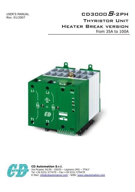
CD3000S-2PH Thyristor Unit Heater Break version
CD3000S-2PH Thyristor Unit Heater Break version
CD3000S-2PH Thyristor Unit Heater Break version

Create successful ePaper yourself
Turn your PDF publications into a flip-book with our unique Google optimized e-Paper software.
CD Automation srl <strong>CD3000S</strong>-<strong>2PH</strong> SSR-HB from 35A to 100A User’s manualImportant warning for safety<strong>Thyristor</strong> units are used in power industrial equipment.The voltages used in the <strong>Thyristor</strong> unit can cause severe electrical shock, and could be lethal.Don't remove the plastic cover.Don't use this unit in aerospace and nuclear application.Electric Shock Hazard (Risque the choque électrique)When thyristor unit has been connected to main supply voltage and is switched off, before to touch it besecure that the unit is isolated and wait at least one minute to allow discharging internal capacitors. Thusbe secure that:• Access to thyristor unit is only permitted to specialised personnel;• The authorised personnel must read this manual before to have access to the unit;• The access to the unit must be denied to unauthorised personnel.Important warnings(attention)Local regulations regarding electrical installation should be rigidly observed.• Safety regulations must be rigidly observed.• Don't bend components to maintain insulation distances.• Protect the unit from high temperature humidity and vibrations.• Don't touch components to prevent electrostatic discharges on them.• Verify that all rating is in line with real needs.• If authorized personnel must measure voltage current etc. on units, take away rings and other jewelsfrom fingers and hands.• Authorized personnel working on thyristor unit under power supply voltage must work on insulatedboard. Be secure that board is not connected to earth.This listing does not represent a complete enumeration of all necessary safety cautions.Protection(protection)CD3000 thyristor unit has a polymeric plastic cover to compliance to International specification IP20.To understand if IP20 protection is sufficient should be evaluated the installation place.Open Type Equipment.Earth(terre)CD3000 family has isolated heatsink. For safety connect the heatsink to earth to avoid shocks in case thatcircuit board or thyristor lose insulation. Earth impedance should be correspondent to local earthregulation. Periodically the earth efficiency should be inspected.Electronic supply (alimentation électronique)CD3000 family electronic circuit should be supplied by dedicated voltage supply for all electronic circuitbut not in parallel with contactor’s coil, solenoids and other inductive or capacitive loads.It’s recommended to use a shielded transformer.Electromagnetic compatibility (compatibilité électromagnétique)Our thyristor units have an excellent immunity to electromagnetic interferences if all suggestionscontained in this manual are respected. In respect to a good Engineering practice, all inductive loads likesolenoids contactor coils should have a filter in parallel.Emissions (emission)All thyristor switching at high speed generate some radiofrequency disturbance. CD3000 seriescompliance with EMC rules for CE mark. In many installations near electronic devices have not been notedproblems. If radiofrequency devices at low frequency are used near the thyristor unit some precautionsshould be taken like line Filters and shielded cables for input signal and for load cables.
CD Automation srl <strong>CD3000S</strong>-<strong>2PH</strong> SSR-HB from 35A to 100A User’s manualQuick StartAttention: this procedure must be carried out by skilled people only.If the Order Code of the <strong>Thyristor</strong> unit is in line with what you really need, then <strong>CD3000S</strong> has beenalready configured in Factory and you just need to do the following steps:1. Verify <strong>CD3000S</strong> Sizing. Be sure that:• The load current is equal or less than the Max current of <strong>CD3000S</strong>.• The load voltage is equal or less than the Max voltage of <strong>CD3000S</strong>.2. Verify the Order Code3. Verify the Installation4. Verify the Diagram of control connection:• All auxiliary connections must be done in line with wirings on this manual.• Verify that there isn’t a short circuit on the load.5. Supply the auxiliary voltage of the unit (see Order Code)6. For size 110A, supply the Fan:• 230VAC ±15% 50/60Hz (standard)• 110VAC ±15% 50/60Hz (Optional)7. Supply the Power unit8. Makes Calibration procedure.The <strong>CD3000S</strong> is ready to start.<strong>CD3000S</strong> SizingWiring with resistive loadDelta wiringStar wiringI=P1,73VV = Nominal load voltage phase to phaseI = Nominal load currentP = Nominal load powerOrder Code<strong>CD3000S</strong>-<strong>2PH</strong>MaxCurrentOperatingVoltageMAXVoltAuxAC/DC35A Write 240Vac 12÷24V SSR ZCInput Firing. Options110vFan45A Operating 480Vac EP75A Voltage 600Vac EFFan at 110VacExternal Protection IP20for size 60÷110AExternal fuses andfuse holders100A
CD Automation srl <strong>CD3000S</strong>-<strong>2PH</strong> SSR-HB from 35A to 100A User’s manualInstallationBefore to install the CD3000 unit examine for damages ordeficiencies. If any is found, notify the carrier immediately. Checkthat the product features shown on CD3000 cover corresponds tothat ordered.CD3000 unit should be always mounted in vertical position toimprove air cooling on heatsink.Maintain minimum distances in vertical and in horizontal asrepresented.Don't install in proximity of hot elements and near units generatingelectromagnetic interferences.When more units are mounted in the same cabinet provide aircirculation as represented.Sometimes it is necessary to provide a fan to have better aircirculation..Dimensions and Fixing holes35÷45A 75÷100A65 mm Ø4,5mm65 mmØ4,5mm120 mm110 mm138 120 mm110 mm117 mm117 mm159 mm159 mmEnvironmental installation conditionsAmbient temperatureStocking temperature -25°C to 70°C0-40°C at nominal current.Over 40°C use the Derating Curve.Installation placeAltitudeHumidityDon’t install at direct sun light, where there areconductive dust, corrosive gas, vibration or waterand also in salty environmental.Up to 1000 meter over sea level. For higher altitudereduce the nominal current of 2% for each 100mover 1000mFrom 5 to 95% without condense and ice
CD Automation srl <strong>CD3000S</strong>-<strong>2PH</strong> SSR-HB from 35A to 100A User’s manualDiagram of control connectionL1L2L3*35÷100A Load TypeL1L2L3Fan Power Supply(Only for size 75- 100A)T1 L2 T3L1L3C1 C2 C3FANDeltaT1T31 2 3 4 5 6 7 8- + + -H.B.Alarm**T1 L2 T3C.T.C.T.C.T.Ext. CAL12-24VdcInput:SSRAux:Star12-24vTO LOADAC/DCNOTE:• The user installation must be protecting by electromagnetic circuit breaker or by fuse isolator.(*)• See par. “HB alarm contact”.(**)Wiring instructionsCD3000 unit has isolated heatsink. For safety connect the heatsink to earth using its terminal with earthsymbol.The CD3000 can be susceptible to airborne interferences from near equipment or from interferences onmain supply, so a number of precautions must be taken.• Contactors coils and chokes must have in parallel a RC filter and must be supplied with a differentvoltage line.• All input/output signals must use screened bifilar wires.• Signal input and output must not route in same cable try and must not be parallel.• Local regulations regarding electrical installation should be rigidly observed.Use copper cables and wires rated for use at 75 °C onlyPower cable torque (suggested)ConnectorCurrentTypeTorqueLb-in (N-m)Wire RangeAWG/kcmilWire TerminalUL Listed (ZMVV)35A, 45A75A, 100AM6 Screw 70.8 (8.0) 1Fork/Spade TerminalCopper Tube Crimp. LugCable dimensions (suggested)Supply Load Earth Auxiliary SupplyCurrent Cable Cable Cable CableScrew M Screw MScrew Mmm² AWGmm² AWG mm² AWGmm² AWG35A 10 8 M6 10 8 M5 6 10 M5 0,50 1845A 10 8 M6 10 8 M5 6 10 M5 0,50 1875A 25 4 M6 25 4 M6 6 10 M5 0,50 18100A 35 3 M6 35 3 M6 6 10 M5 0,50 18
CD Automation srl <strong>CD3000S</strong>-<strong>2PH</strong> SSR-HB from 35A to 100A User’s manualTechnical SpecificationsGeneral featuresInput featuresCover and Socketmaterial:PolymericV2Logic input SSR:(Standard)4 ÷ 30Vdc 5mA Max(ON ≥ 4VdcOFF < 1Vdc)Heat-sink:Anodized aluminumDelay switch ON time:0.5 period MaxDelay switch OFF time:Auxiliary Voltage:Fan voltage:(Only for size 75÷100A)0.5 period Max12÷24V dc/ac(max 100mA)230Vac ±15% 14W(110Vac opt.)<strong>Heater</strong> <strong>Break</strong> AlarmIs a microprocessor based circuit to diagnosepartial or total load failure and short circuit onSCR and fuses failure.Discrimination better than 20%.Latching alarmRelay Output:0.5A at 125VACPower output featuresSizeVoltagerangeRepetitive peakreverseVoltageLatchingcurrentMax peakone cycleLeakagecurrentI 2 T valuethyristorFrequencyrangePower lossIsolationVoltage(A) (V) 480V 600V (mAeff) (10ms) (A) (mAeff) tp=10msec (Hz)I=Inom(W)Vac35A 24÷600 1200 1600 300 460 15 1030 47÷70 82 250045A 24÷600 1200 1600 450 1000 15 4750 47÷70 108 250075A 24÷600 1200 1600 450 1350 15 8830 47÷70 180 2500100A 24÷600 1200 1600 450 2000 15 19100 47÷70 240 2500Derating CurveLed status and AlarmsThe following events and alerts don’t stop theunit:• SCR Short Circuit• <strong>Heater</strong> <strong>Break</strong>When one of these alarms is active, the HB relaychange status.LED STATUS DESCRIPTIONONSCHBLoad IS NOT PoweredLoad IS PoweredSCR OKSCR short circuitLoad OKLoad Fault= OFF= ON
CD Automation srl <strong>CD3000S</strong>-<strong>2PH</strong> SSR-HB from 35A to 100A User’s manual<strong>Heater</strong> break alarm and SCR short circuitThe <strong>Heater</strong> <strong>Break</strong> circuit to work properly must have at least an input of 25% of the nominalcurrent.H.B. circuit read load current via a current transformer 25-50/0.05 or 100/0.05 depending on thyristorsize.Minimum current is 30% of the current transformer size’s. If load current is below this value make twoturns or more around current transformer. H.B. circuit also diagnoses fuse failure.HB alarm contact<strong>CD3000S</strong> is supplied with <strong>Heater</strong> <strong>Break</strong> (HB) alarm contact normally opened (NO):• In normal conditions (without alarm) and with auxiliary power supply, the contact to the terminalshas opened (relay coil energized).• In alarm condition or without auxiliary power supply the contact to the terminals is closed (relay coilnot energized).if you wish to change the alarm contact put the jumper as shown:35÷100AJP1A B CTypeNO(standard)NCJP1A-BB-C<strong>Heater</strong> break Calibration procedureAn automatic function sets the <strong>Heater</strong> <strong>Break</strong> Alarm.The auto setting function can be activated using the “CAL” button on front unit, or supply with 12-24Vdcthe digital input "Cal Ext." (See Diagram of control connection).The <strong>Heater</strong> <strong>Break</strong> calibration procedure is performed in this way:• <strong>CD3000S</strong> gives the maximum voltage output• all LEDS are on, this means that calibration procedure is active• The values of voltage and current are stored in memory• After a minute the <strong>CD3000S</strong> comes back to the initial situationIf load current decreases for partial or total load failure (sensitivity 20%) the yellow LED become ON andalarm relay change status.If CD3000 is still in conduction with no input signal (LED green OFF) it means that there is a short circuiton thyristors and red LED (SC) become ON.If the load has been changed the <strong>Heater</strong> <strong>Break</strong> calibration procedure must be done again.
CD Automation srl <strong>CD3000S</strong>-<strong>2PH</strong> SSR-HB from 35A to 100A User’s manualFiring settingZC firing mode is used with Logic Output from temperature controllers and the <strong>Thyristor</strong> operates like acontactor. The Cycle time is performed by temperature controller. ZC minimizes interferences because the<strong>Thyristor</strong> unit switches ON-OFF at zero voltage.VOLTAGE SUPPLY (V)LOAD VOLTAGE (V)SSR from controllerInput settingThe input type is already configured in line with customer requirements that are defined in the completeproduct code. However, verify that the jumper are set as below represented:35÷100AInput JP2 JP3 JP6SSR Open B-C A-BJP3C B AJP6C B AJP2
CD Automation srl <strong>CD3000S</strong>-<strong>2PH</strong> SSR-HB from 35A to 100A User’s manualFuses and Fuse holderWarning: High speed fuses are only used for the thyristor protection and can not be used toprotect the installation.<strong>CD3000S</strong> unit must be protected against short circuit by High speed fuses.The Fuses must have I²t 20% less than thyristor’s I²t.The warranty of thyristor is null if no proper fuses are used. See tabFuses and Fuse Code for CE.Fuse and Fuse holderCurrentI²TSizeFuse CODECODE(ARMS)(A² sec.)35A FFH1451/40A FU1451/40A 40 165045A FFH1451/63A FU1451/63A 63 400075A FFH2258/100A FU2258/100A 100 13500100A FFH2760/160A FU2760/160A 160 15000Fuse Holder sizeFor size from 35A - 45AFor size 75AFor size from 100A
CD Automation srl <strong>CD3000S</strong>-<strong>2PH</strong> SSR-HB from 35A to 100A User’s manualMaintenanceIn order to have corrected cooling, the user must clean the heatsink and the protective grill of the fans.The frequency of this servicing depends on environmental pollution.Also check periodically if the screw for the power cables and safety earth are tightened correctly(See Diagram of control connection)Trouble ShootingSmall problems sometimes can be solved locally with the help of the below tab of trouble shooting. If youdon’t succeed, contact us or your nearest distributor.SymptomIndication onfront unitPossible reasons of thesymptomActions<strong>Thyristor</strong> unitdoesn’t go inconduction withinput signalGreen LED (ON)light offGreen LED (ON)light off• No voltage auxiliary power• No input signal• Reversed polarities of inputsignal• Fuse failure• Load failure• Load connection interruption• <strong>Thyristor</strong> faulty• Give auxiliary voltage supply(See Diagram of connection)• Provide to give input signal• Reverse the input signal polarity• Substitute the fuse• Check the load• Check the wiring• Substitute the faulty thyristorThe yellow led (HB) is light onLoad currentflows also with noinput signalGreen LED (ON)is always light on• Wrong wiring• Short circuit on thyristorThe red led (SC) is light on• Check the load wiring• Substitute the thyristorCurrent flows atnominal value butYellow LED (HB)is light onYellow LED (HB)light on• HB circuit not tuned• Current transformers notproperly wired• Make HB calibration procedure• Control current transformerswiringCurrent flows atnominal value butRed LED (SC) islight onRed LED (SC)light on• HB circuit not tuned • Make HB calibration procedure<strong>Thyristor</strong> unitdoesn’t workproperly• Auxiliary voltage supply out oflimits• Wrong input signal selection.• Wrong input signal calibration(out of range)• Verify the auxiliary voltagesupply• Control input signal setting.• Repeat input calibrationprocedure.Warranty conditionCD Automation gives a 12 months warranty to its products. The warranty is limitedto repairing and parts substitution in our factory and does exclude products notproperly used and fuses.Warranty does not include products with serial numbers deleted.The faulty product should be shipped to CD Automation at customer’s cost and ourService will evaluate if product is under warranty terms.Substituted parts remain of CD Automation propertyENG <strong>CD3000S</strong>-<strong>2PH</strong>__35-100A_SSR-HB - 03.doc