Series E Installation Manual PDF - Myers Power Products, Inc.
Series E Installation Manual PDF - Myers Power Products, Inc.
Series E Installation Manual PDF - Myers Power Products, Inc.

You also want an ePaper? Increase the reach of your titles
YUMPU automatically turns print PDFs into web optimized ePapers that Google loves.
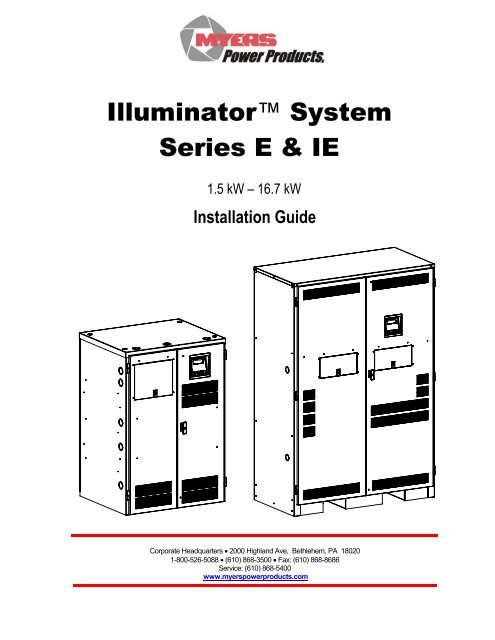
Illuminator System<strong>Series</strong> E & IE1.5 kW – 16.7 kW<strong>Installation</strong> GuideCorporate Headquarters • 2000 Highland Ave, Bethlehem, PA 180201-800-526-5088 • (610) 868-3500 • Fax: (610) 868-8686Service: (610) 868-5400www.myerspowerproducts.com
This unit contains LETHAL VOLTAGES. All repairs and service should be performed byAUTHORIZED SERVICE PERSONNEL ONLY! There are NO USER SERVICEABLEPARTS inside this unit.IMPORTANT SAFEGUARDSWhen using electrical equipment, you should always follow basic safetyprecautions, including the following:1. READ AND FOLLOW ALL SAFETYINSTRUCTIONS.2. Do not install the system outdoors.3. Do not install near gas or electric heaters or in other high-temperaturelocations.4. Use caution when servicing batteries. Depending on battery type, batteriescontain either acid or alkali and can cause burns to skin and eyes. Ifbattery fluid is spilled on skin or in the eyes, flush with fresh water andcontact a physician immediately.5. Equipment should be mounted in locations where unauthorized personnelwill not readily subject it to tampering.6. The use of accessory equipment not recommended by Manufacturer maycause an unsafe condition and void the warranty.7. Do not use this equipment for other its than intended use.8. Qualified service personnel must perform all servicing of this equipment.SAVE THESE INSTRUCTIONSThe installation and use of this product must comply with all national, federal,state, municipal, or local codes that apply. If you need help, please callService at 1-610-868-5400.1114061 -System <strong>Installation</strong> <strong>Manual</strong>
C A U T I O NREAD ENTIRE MANUAL AND REVIEW ALL DOCUMENTATION BEFORE ATTEMPTING SYSTEMINSTALLATION!FOR SERVICE OR INSTALLATION INFORMATION:TELEPHONE: (610) 868-5400 (24 HR. HOTLINE)FAX: (610) 954-8227FOR YOUR PROTECTION....PLEASE COMPLETE AND RETURN WARRANTY REGISTRATION CARD IMMEDIATELY.2114061 -System <strong>Installation</strong> <strong>Manual</strong>
C H A P T E R 1SAFETY WARNINGSRead the following precautions before you install the system.IMPORTANT SAFETY INSTRUCTIONSSAVE THESE INSTRUCTIONS. This manual contains important instructions that you shouldfollow during installation and maintenance of the system and batteries. Please read all instructionsbefore operating the equipment and save this manual for future reference.DANGERThis system contains LETHAL VOLTAGES. AUTHORIZED SERVICE PERSONNEL shouldperform all repairs and service ONLY. There is NO USER SERVICEABLE PARTS inside thesystem.• Do not install the system outdoors.WARNING• Do not install near gas or electric heaters or in other high-temperature locations.• Use caution when servicing batteries. Battery acid can cause burns to skin and eyes. If acid isspilled on skin or in the eyes, flush with fresh water and contact a physician immediately.• Equipment should be mounted in locations where unauthorized personnel do not readily subjectit to tampering.• The use of accessory equipment not recommended by the manufacturer may cause an unsafecondition.• Do not use this equipment for other than intended use.• Only qualified service personnel (such as a licensed electrician) should perform the system andbattery installation and initial startup. There is a risk of electrical shock.3114061 -System <strong>Installation</strong> <strong>Manual</strong>
Location GuidelinesKeep the following guidelines in mind when choosing the location for your system and batteries:• Verify that the environment meets the requirements in “Storage and Operating Environment” onpage 7. The environment can affect the reliability and performance of both the unit and thebatteries.• Choose a permanent location for the unit. Attempting to move the unit after you have installed thebatteries can damage the batteries and the cabinet.CAUTIONDo not move the unit after you install the batteries. If you do, the unit and batteries may bedamaged.CEC requires the unit to be located in a service room. If the room is equipped with a sprinklersystem, the unit must be provided with sprinkler proof covers.The system should be connected to the emergency generator, if available.This equipment is heavy. Refer to Table 3.4 when you choose a site to make sure that the floorcan support the weight of the system, the batteries, and any other necessary equipment.Table 3.4 System weight [in lbs. (kg)]System Models for 90 Minute run-timeUnit with StandardSLC BatteriesUnit withoutBatteriesUnit with StandardSLC BatteriesUnit withoutBatteries1.5kw 2.25kw 3.0kw 3.75kw 5.0kw 6.0kw 8.0kw 10.0kw 12.5kw 16.7kw511(232)215(97)674(305)230(104)674(305)230(104)827(376)235(107)827(376)235(107)980(445)240(109)980(445)240(109)1168(530)280(127)1715(778)605(274)2120(962)640(290)System Models for 120 Minute run-time1168(530)280(127)1715(778)605(274)2120(962)640(290)2561(1162)785(356)2561(1162)785(356)3025(1373)805(366)3025(1373)805(366)3845(1744)885(401)3845(1744)885(401)ConsultFactory885(401)Receiving and Moving the Unit and the BatteriesSystems weigh several hundred pounds, (see Table 3.4; ask your sales representative for additionalinformation). Make sure you are prepared for these weights before you unload or move the unit or thebatteries. Do not install any batteries until you have permanently installed the unit and connected allconduit and wiring.6114061 -System <strong>Installation</strong> <strong>Manual</strong>
Storage and Operating EnvironmentMake sure you store and install the system in a clean, cool, dry place with normal ventilation and levelfloors.Storage TemperatureStore the batteries (in the system) at -18 to 40°C (0 to 104°F). Batteries have a longer shelf life if theyare stored below 25°C (77°F). Keep stored batteries fully charged. Recharge the batteries every 90–180 days. The system without batteries may be stored at -20 to 70°C (-4 to 158°F).VentilationThe air around the unit must be clean, dust-free, and free of corrosive chemicals or othercontaminants. Do not place the system or batteries in a sealed room or container.Operating TemperatureSystem can operate from 20° to 30°C (68° to 86°F) and up to 95% relative humidity. The batteries’service life is longer if the operating temperature stays below 25°C (77°F).BatteriesThe temperature should be near 25°C (77°F) for optimum battery performance. Batteries are lessefficient at temperatures below 18°C (65°F), and high temperatures reduce battery life. Typically, atabout 35°C (95°F), battery life is half of what it would be at a normal temperature of 25°C (77°F). Atabout 45°C (113°F), battery life is one-fourth of normal.Make sure that heaters, sunlight, air conditioners, or outside air vents are not directed toward thebatteries. These conditions can make the temperature within battery strings vary, which can causedifferences in the batteries’ voltages. Eventually, these conditions affect battery performance.Do not allow tobacco smoking, sparks, or flames in the system location because hydrogen isconcentrated under the vent cap of each cell of the battery. Hydrogen is highly explosive, and it ishard to detect because it is colorless, odorless, and lighter than air.Every type of battery can produce hydrogen gas, even sealed maintenance-free batteries. The gas isvented through the vent caps and into the air, mainly when the unit is charging the batteries. Thebatteries produce the most hydrogen when maximum voltage is present in fully charged batteries; thebatteries do not produce hydrogen during float charging. The amount of current that the chargersupplies to the batteries (not the battery ampere-hour) determines how much hydrogen is produced.High Altitude OperationThe maximum operating ambient temperature drops 1°C per 300m (2°F per 1000 ft) above sea level.Maximum elevation is 3000m (10,000 ft).7114061 -System <strong>Installation</strong> <strong>Manual</strong>
C H A P T E R 4INSTALLATION OVERVIEWFigure 4.1 shows typical installations of system. Standard 1.5 kW, 2.25 kW, 3.0 kW, 3.75 kW, 5.0 kW,6.0 kW, 8.0 kW, 10.0 kW, 12.5 kW, and 16.7 kW models do not have external battery cabinets.BuildingServicePanelToSupportedLoadsBuildingServicePanelToSupportedLoadsFigure 4.1 Typical Hardwired <strong>Installation</strong>8114061 -System <strong>Installation</strong> <strong>Manual</strong>
C H A P T E R 5AC INPUT & AC OUTPUT INSTALLATIONWARNINGOnly qualified service personnel (such as a licensed electrician) should perform the ACinstallation. There is a risk of electrical shock.Read the following cautions before you continue.CAUTION• Unit contains hazardous AC and DC voltages. Because of these voltages, a qualifiedelectrician must install the system, AC line service, and batteries. The electrician mustinstall the AC line service according to local and national codes and must be familiarwith batteries and battery installation.• Before you install, maintain, or service the unit, always remove or shut off all sources ofAC and DC power and shut off the system. You must disconnect AC line input at theservice panel and turn off the <strong>Installation</strong> Switch (S1), the Main AC Input CircuitBreaker (CB1), and the Battery Fuse(s) to make sure the unit does not supply outputvoltage.• Whenever AC and/or DC voltage is applied, there is AC voltage inside the unit; this isbecause the unit can supply power from AC line or from its batteries. To avoidequipment damage or personal injury, always assume that there may be voltage insidethe unit.• Remove rings, watches, and other jewelry before installing the AC wiring. Always wearprotective clothing and eye protection and use insulated tools when working nearbatteries. Whenever you are servicing an energized unit with the inside panel open,electric shock is possible; follow all local safety codes. TEST BEFORE TOUCHING!• To reduce the risk of fire or electric shock, install the unit and its batteries in atemperature and humidity-controlled indoor area free of conductive contaminants. Seepage 7 for operating environment specifications.1. Open the unit’s doors. Make sure the installation switch and the input circuit breaker areoff, and the battery fuse(s) removed.2. Look at the ID label on the inside right door. Write down the following information:Input Voltage: __________Output Voltage: __________3. Now, make sure the input and output voltages are what you need. Remember that thesystem provides single-phase power only.• Does the input voltage available for the system at the AC service panel match theinput voltage shown on the unit’s ID label?Service Panel Voltage = ____________ Input Voltage __Yes /__No• Does the output voltage on the ID label match the voltage your loads (protectedequipment) need?Load Voltage = _____________ Output Voltage __Yes/__NoIf you answered NO to either of the preceding questions, call SERVICE.9114061 -System <strong>Installation</strong> <strong>Manual</strong>
4. Now, use the information you wrote down in Step 2 to find the correct circuit breaker forthe service panel that is for your system.Table 5.1 Recommended Circuit Breaker for Maximum Input CurrentSystem Input Voltage (Vac) Max. Current RecommendedCircuit Breaker1.5 kW 120V 16 amps 20A1.5 kW 208V 9 amps 15A1.5 kW 240V 8 amps 10A1.5 kW 277V 7 amps 10A2.25 kW 120V 24 amps 30A2.25 kW 208V 14 amps 20A2.25 kW 240V 12 amps 15A2.25 kW 277V 11 amps 15A3.0 kW 120V 32 amps 40A3.0 kW 208V 18 amps 25A3.0 kW 240V 16 amps 20A3.0 kW 277V 14 amps 20A3.75 kW 120V 39 amps 50A3.75 kW 208V 23 amps 30A3.75 kW 240V 20 amps 25A3.75 kW 277V 17 amps 25A5.0 kW 120V 52 amps 70A5.0 kW 208V 30 amps 40A5.0 kW 240V 26 amps 35A5.0 kW 277V 23 amps 30A6.0 kW 120V 63 amps 80A6.0 kW 208V 36 amps 45A6.0 kW 240V 32 amps 40A6.0 kW 277V 27 amps 35A8.0 kW 120V 84 amps 100A8.0 kW 208V 48 amps 60A8.0 kW 240V 42 amps 50A8.0 kW 277V 36 amps 45A10.0 kW 120V 98 amps 125A10.0 kW 208V 60 amps 80A10.0 kW 240V 52 amps 70A10.0 kW 277V 45 amps 60A12.5 kW 120V 131 amps 175A12.5 kW 208V 75 amps 90A12.5 kW 240V 65 amps 80A12.5 kW 277V 57 amps 70A16.7 kW 120V 174 amps 225A16.7 kW 208V 100 amps 125A16.7 kW 240V 87 amps 110A16.7 kW 277V 76 amps 100AWARNING: THE EXTERNAL INPUT CIRCUIT BREAKER PROTECTING THE SYSTEM MUSTBE A “MOTOR START”, DELAYED TRIP TYPE. * IF INPUT AUTO OR INPUTISOLATION TRANSFORMER WAS ADDED TO THE SYSTEM. CONSULTFACTORY. THIS IS DUE TO MAGNETIC INRUSH CURRENT DRAWN DURINGAPPLICATION OF AC POWER.10114061 -System <strong>Installation</strong> <strong>Manual</strong>
5. Write down the circuit breaker value that applies to your system from Table 5.1:__________6. Now, look at Table 5.2 below, and use the notes below to find the proper gauge wirefor the recommended circuit breaker recorded in step 5.Table 5.2 Recommended Minimum Wire SizesRead These Important Notes! For this Input Use this Size 90°CCircuit Breaker Copper WireSize...This table lists the AWG and mm2 wire size for each circuit breaker size.The minimum recommended circuit breaker sizes for each model andvoltage application are listed in Table 5.1. The temperature rating ofconductor must not be less than 90° C wire. Based on the ampacitiesgiven in Tables 310-16 of the National Electrical Code, ANSI/NFPA 70-1993 (Table 2 of the CEC), and NEC article 220 (CEC Section 4). Allcircuit conductors, including the neutral and equipment-groundingconductors, must be the same size (ampacity) wires. Code may requirea larger wire size than shown in this table because of temperature,number of conductors in the conduit, or long service runs. Follow localcode requirements.AWGMm210, 15, 20 12 3.3125, 30 10 5.2635, 40, 45 8 8.3650, 60 6 13.3070, 80 4 21.1590, 100 2 33.62110 1 42.11125 1/0 53.49150, 175 3/0 67.43225 4/0 74.407. The input circuit breaker in the input service panel provides the means for disconnecting ACto the unit. Only authorized persons shall be able to disconnect AC to the unit [see NEC 700-20and 700-21(CEC Section 46)]. If you are using the input circuit breaker to disconnect AC, youmust make sure that only authorized persons have control of the circuit breaker panel to meetthe requirements of NEC 700-20 (CEC Section 46).8. Read the following caution, before removing conduit knockouts.CAUTIONTo prevent electrical shock or damage to your equipment, the <strong>Installation</strong> Switch (S1), the MainAC Input Circuit Breaker (CB1), and the circuit breaker at the input service panel should all beturned off. The Main DC Battery Fuse and the Battery Disconnect Fuse(s) (if you have one)should be removed.9. Remove knockouts for AC Input and AC Output in the top or left and right side of the system(See figure 4.1). AC input conductors and AC output conductors must be installed in separateconduits, and emergency and non-emergency output circuits must be installed in separateconduits.CAUTIONDo not drill the cabinet; drill filings may damage the unit and keep it from operating. If youneed larger knockouts, use a chassis punch to punch out the appropriate knockout. Do notcreate additional knockouts.10. Install the conduit. You must run the AC input service conductors and AC output conductorsthrough separate conduits. Emergency output conductors and non-emergency output conductorsmust also be run through separate conduits. Emergency output circuits shall be installed indedicated conduit systems and not shared with other electrical circuits as described in NEC 700-9(b) [CEC Section 47-108].11114061 -System <strong>Installation</strong> <strong>Manual</strong>
Figure 5.1 AC Connections for 1.5 k W– 5.0 kW systemsFigure 5.2 AC Connections for 6 kW – 16.7 kW systems (5.0 kW system for 120 Minute run-time)13114061 -System <strong>Installation</strong> <strong>Manual</strong>
C H A P T E R 6INSTALLING BATTERIES AND DC WIRINGWARNINGOnly qualified service personnel (such as a licensed electrician) should perform thebattery and DC wiring installation. There is a risk of electrical shock.This section explains how to install system batteries, fuses, and cables. For all models, youmust install the batteries in the system cabinet. An electrician who is familiar with batteryinstallations and applicable building and electrical codes should install the batteries.WARNINGThe batteries that will need to be installed in this system could cause you harm or severelydamage the electronics if proper precautions are not followed. Batteries connected in seriesparallel configuration could produce lethal voltages with unlimited current. All batteriesshould be inspected for damage prior to installation. Never install a battery that is leakingelectrolyte. Battery terminals should be cleaned with a wire brush to remove any oxidation.All tools should be insulated. Rubber gloves and safety glasses are recommended. IN THISSYSTEM BATTERY NEGATIVE IS TIED TO GROUND INSIDE THE INVERTER. Thismeans that the cabinet and shelves are at ground potential as soon as negative connectionsare made to the batteries. It is strongly recommended to make all negative connections tothe batteries the last step to prevent any chance of shorting battery positive to ground. Withthe DC fuse(s) removed, make connections to battery positive first, working your way towardsbattery negative. Leave individual strings of batteries open at the last battery negative untilall batteries are installed. Then connect each string’s negative.Safety InstructionsIMPORTANT SAFETY INSTRUCTIONSSAVE THESE INSTRUCTIONSThis section contains important instructions that a qualified service person shouldfollow during installation and maintenance of the system and batteries. ONLY aqualified service person should work with the batteries.CAUTIONFull voltage and current are always present at the battery terminals. The batteries usedin this system can produce dangerous voltages, extremely high currents, and a risk ofelectric shock. They may cause severe injury if the terminals are shorted together or toground (earth). You must be extremely careful to avoid electric shock and burnscaused by contacting battery terminals or shorting terminals during battery installation.Do not touch un-insulated battery terminals.14114061 -System <strong>Installation</strong> <strong>Manual</strong>
A qualified electrician familiar with battery systems and required precautions mustinstall and service the batteries. Any battery used with this unit shall comply with theapplicable requirements for batteries in the standard for emergency lighting and powerequipment, UL 924 (Canada’s National Building Code). Cabinets are designed to beused with, and batteries must be replaced with, manufacturer battery number BAT-CG12105 or a manufacturer approved equivalent (see the battery wiring diagram thatcame with the battery cables). If you substitute batteries not supplied by manufacturer,the unit’s UL (cUL) listing is void and the equipment may fail. <strong>Installation</strong> must conformto national and local codes as well. Keep unauthorized personnel away from batteries.The electrician must take these precautions:Wear protective clothing and eyewear. For battery systems >48vdc, wear rubbergloves and boots. Batteries contain corrosive acids or caustic alkalis and toxicmaterials and can rupture or leak if mistreated. Remove rings and metal wristwatchesor other metal objects and jewelry. Don’t carry metal objects in your pockets where theobjects can fall onto the batteries or into the system.Tools must have insulated handles and must be insulated so that they do not shortbattery terminals. Do not allow a tool to short a battery terminal to another batteryterminal or to the cabinet at any time. Do not lay tools or metal parts on top of thebatteries, and do not lay them where they could fall onto the batteries or into thecabinet.Install the batteries as shown on the battery-wiring diagram provided with the system.When connecting cables, never allow a cable to short across a battery’s terminals, thestring of batteries, or to the cabinet.Align the cables on the battery terminals so that the cable lug does not contact any partof the cabinet even if the battery is moved. Keep the cable away from any sharp metaledges.CAUTIONInstall the battery cables so the system doors cannot pinch them.If you are replacing batteries or repairing battery connections, follow the procedure inthe system user’s Guide to shut down your system and remove both AC and DC inputpower.15114061 -System <strong>Installation</strong> <strong>Manual</strong>
Before Installing the BatteriesToolsCAUTIONAlways use insulated tools when you work with batteries. Always torque connections tothe manufacturer’s recommendations.When you work with system batteries, you need the following tools. The tools mustbe insulated so they do not short battery terminals to the cabinet. Wear the safetyequipment required by local code whenever the doors are open and whenever youare working on batteries. Other tools may be necessary for optional batteries.• Digital volt-ohm meter• 7/16” socket wrench• 3” extension socket• Ratchet• Wire brush• Electrical tape• Conductive grease or petroleum jelly• Brush (to apply grease or petroleum jelly to terminals)• Safety equipment required by local codes• Torque wrench calibrated in inch-pounds or Newton-meters• Safety glasses with side shieldsBattery Voltage (vdc)Models 1.5k 2.25k 3.0k 3.75k 5.0k 6.0k 8.0k 10.0k 12.5k 16.7kBattery Volts for 90Minute SystemsBattery Volts for120 MinuteSystems48v 72v 96v 120v 144v 180v 240v 144v 180v 240v72v 96v 120v 144v 180v 240v 144v 180v 240v 240vBattery Cable SizingThe battery cable or wire used is No. 6 AWG (13.30 mm 2 ) for all applications:DC DisconnectSystems have a Main Battery Fuse (F1) inside the cabinet; this fuse lets you remove DCpower from the batteries. Systems (10 KW – 16.7KW) have a fuse in line with the positivecable leaving each battery string.Installing and Connecting the BatteriesBattery Wiring DiagramYou should have received a battery-wiring diagram with your system. This battery-wiringdiagram shows how you should install the batteries, make terminal, and fuse connections. Usethe diagram as you follow the steps below.16114061 -System <strong>Installation</strong> <strong>Manual</strong>
LocationThe system batteries belong inside the unit. Before you start installing the batteries, you mustinstall the system in its permanent location. If you have not already done this, see “LocationGuidelines” on page 6 to choose a location.CAUTIONTo prevent damage to your equipment, do not move the system after the batteries areinstalled.To make sure a location is acceptable for the system, review the requirements in Chapter 3.Electronics Cabinet Battery Block ConnectionsDo not connect any battery cables at this time. In the following procedure, you shouldonly make connections to the electronics cabinet’s battery block. Use the battery-wiringdiagram shipped with the system as you follow these steps.1. Find the positive battery cable that connects to the battery block. At the bare endof the cable, strip off 0.5” (1.3 cm) of insulation. Connect the cable to the batteryblock. Torque the connection as shown on the battery-wiring diagram.2. Find the negative battery cable that connects to the battery block. At the bareend of the cable, strip off 0.5” (1.3 cm) of insulation. Connect the cable to thebattery block. Torque the connection as shown on the battery-wiring diagram.Insulate the other end of the cable.3. If your unit has only has one battery string, go on to the Arranging the Batteriessection.Repeat step 1 and 2 for units with 2 strings (10 kW, 12.5 kW, and 16.7 kWsystems).Arranging the BatteriesNOTE As you arrange the batteries, you must be wearing the required safetyequipment.Arrange the batteries in the cabinet only as shown in the battery-wiring diagram. Thisarrangement is designed to maximize airflow around the batteries. The cabinets aredesigned so that battery cases should never touch. Air should be free to circulate. Cleanthe entire surface of all battery terminals with the wire brush before you install thebatteries to create good contact points.Load the batteries into the system. Starting with the bottom shelf, load one shelf at atime.CAUTIONNever install the batteries in an airtight enclosure.Connecting the Cables Between BatteriesWhen you make battery terminal connections, use the torque wrench to tighten thebattery terminal connections securely. You can find out what torque value to use byfinding the battery number on the front of the battery. Then, use Table 6.1 to find thetorque value for that battery.17114061 -System <strong>Installation</strong> <strong>Manual</strong>
Table 6.1 Battery TorqueBattery TypeSL-12105SL-12105MBAT-CG12105BAT-CG12105BTorqueTorque to 120 in lbs. (13.6 Nm)Torque to 120 in lbs. (13.6 Nm)Torque to 120 in lbs. (13.6 Nm)Torque to 55 in lbs. (6.5 Nm)Now, follow these steps to connect the cables:1. Using the battery-wiring diagram, determine which batteries belong to eachbattery string.NOTE: For standard 90-minute runtimes, 1.5 kW, 2.25 kW, 3.0 kW, 3.75 kW, 5.0 kW,6.0 kW and 8.0 kW models have only one battery string. 10.0 kW, 12.5 kW, and16.7 kW models have two battery strings.For 120-minute runtimes, 8.0KW model has two battery strings.2. Clean the cable connectors with the wire brush before you make the batteryconnections.NOTE As you carry out the following step, use these guidelines:If you are using conductive grease, apply a thin coating of high-temperatureconductive grease on each post and every cable connector before you assembleand torque the connection to slow corrosion.If you use nonconductive grease like petroleum jelly, do not apply any greasebefore you make the connections and torque them. Instead, make the connectionfirst; then, torque it to the value shown in Table 6.1. After you make the connection,apply a coating of the nonconductive grease to the hardware at the batteryterminals.3. In each battery string, connect the battery cables between the batteries asshown in the battery-wiring diagram (positive terminal to negative terminal).Torque the connections to the value shown for your battery in Table 6.1.4. Connect the battery cables from one shelf to the next as shown on the batterywiringdiagram.5. Connect the fuse block to the positive of the battery as shown on the batterywiringdiagram.CAUTIONHazardous voltage is present! System batteries are high current sources. Thesebatteries can produce dangerous voltages, extremely high currents, and a risk ofelectric shock.6. Install only the battery fuses (10.0KW – 16.7KW). Next, use the voltmeter tocheck the DC voltage between the positive (+) position on the battery blockinside the electronics cabinet and the unconnected battery negative terminal.This voltage should be approximately the battery voltage record on the unit IDlabel. If it is greater than + or – 5% Vdc, review the battery wiring diagram.Correct any wiring errors and recheck the DC voltage; do not go on until yourmeasurement is within + or – 5% Vdc. If the measurement is too high and youcannot find the cause of the problem, call SERVICE.18114061 -System <strong>Installation</strong> <strong>Manual</strong>
CAUTIONIf you do not verify that voltage and current direction are correct, the equipment mayfail.Connecting the Negative Battery Cable(s) to the Battery String(s)Remove the insulation from the cable that was put on in step 2 of “Electronicscabinet battery block connections”. Connect the cable to the battery (-) negative.Repeat this step for systems with 2 strings.Replacing the BatteriesCAUTIONA battery can present a risk of electrical shock and high short circuit current. A qualifiedelectrician familiar with battery systems should service the batteries.Review all the safety instructions at the beginning of this chapter before you replace anybatteries.Use the Same Quantity and Type of BatteryCAUTIONYou must use the same quantity and type of battery. Substituting batteries not suppliedby manufacturer voids the UL (CUL) listing and may cause equipment damage.To ensure continued superior performance of your system and to maintain proper chargeroperation, you must replace the batteries in the system with the same number of batteries.These batteries must be the same types as the original batteries. The replacement batteriesshould have the same voltage and ampere-hour rating as the original batteries.Handle Used Batteries with Care!Assume that old batteries are fully charged. Use the same precautions you would use whenhandling a new battery. Do not short battery terminals or the battery string with a cable or toolwhen you disconnect the batteries! Batteries contain lead. Please dispose of old batteriesproperly.CAUTIONDo not dispose of batteries in a fire because the batteries could explode. Do not openor mutilate batteries. Released electrolyte is harmful to the skin and eyes. It may betoxic.Dispose of Batteries ProperlyCAUTIONBatteries contain lead. Many state and local governments have regulations about usedbattery disposal. Please dispose of the batteries properly.19114061 -System <strong>Installation</strong> <strong>Manual</strong>
CHAPTER 7TURNING ON THE SYSTEM AND SETTINGPARAMETERSSeveral parameters in the system software determine when and how your system conductsthe automatic monthly and annual tests. Refer to “User Setup” in the “Front Panel Display”chapter of the system user’s Guide for a description of each test.Starting the UnitBefore you can set the parameters, you must start the system.WARNINGVerify that the system AC Input Circuit Breaker and <strong>Installation</strong> Switch are off.1. Turn on the AC input at the building service panel; ensure that the systems inputbreaker (CB1) is off.2. Locate the DC Pre-charge Switch (S2), see figure 7.1 or figure 7.2 or figure 7.3;press it for five seconds; then, install the main battery fuse (F1) inside theelectronics cabinet.3. Turn on the System AC input circuit breaker (CB1). (See figure 5.1 or figure 5.2)4. Turn on the <strong>Installation</strong> Switch (S1). Leave the loads (protected equipment) off.Unit will run on batteries, then transfer to normal mode.Figure 7.1 Battery Fuse, DC Pre-charge Switch & <strong>Installation</strong> Switch (1.5 kW – 5.0 kW)20114061 -System <strong>Installation</strong> <strong>Manual</strong>
Figure 7.2 Battery Fuse, DC Pre-charge Switch & <strong>Installation</strong> Switch (6 kW – 8 kW)(5 kW System for 120 Minute run-time)Figure 7.3 Battery Fuse, DC Pre-charge Switch & <strong>Installation</strong> Switch (10 kW – 16.7 kW)(8 kW System for 120 Minute run-time)21114061 -System <strong>Installation</strong> <strong>Manual</strong>
Front Panel DisplayThe Front Panel Display assembly consists of a 4 x 20 vacuum fluorescent displayand a 4-button keypad. The 4 buttons can navigate through all the menus by usingthe left and right arrow keys, the ENTER and the ESCAPE.The default menu will scroll between the status screen and the Identification/Date-Time screen. To view the other menu options from the default screen, press theENTER key, and then press the left or the right arrow key to go to the desired menu.The Menu’s available are Meter, Test Log, Event Log, Alarm Log, User Setup,Factory Setup, Status, System Information, and Test Mode.Once the desired menu has been reached, press the ENTER key to gain access tothis menu. Once into the menu, use the left or right arrow key to scroll to differentfunctions within the menu. Press the ENTER key again to gain access to the desirefunction. To exit, press the ESCAPE key until the desired level has been reached.(See figure 7.4)Control Panel KeypadsKey NameTable 7.1 Keypad FunctionsFigure 7.4 Front Panel DisplayDescriptionEnter (Blue) Pressing this key will view menus.Escape (Black) Pressing this key will exit out of menus and return to theIdentification/Date-Time screen.[ ◄ ] (Red) This key functions as Left scroll key.[ ► ] (Red) This key functions as Right scroll key.22114061 -System <strong>Installation</strong> <strong>Manual</strong>
Meter FunctionsTo get to the meter functions from the default screen, press the ENTER key, scroll tothe METER menu using the left or the right arrow key, then press the ENTER keyagain. Use left or the right arrow key to view the meter function desired.FunctionTable 7.2 Meter FunctionsDescriptionVoltage Input Measures the AC Input Voltage to the Inverter.Voltage Output Measures the AC Output Voltage from the Inverter.Current Output Measures the AC Output Current from the Inverter. If there are Normally Offloads connected, it will read the sum of Normally On and Normally Offoutputs.Battery Voltage Measures DC Battery Voltage.Battery Current Measures the DC Battery Current. When in charge mode, the current will bepositive. When in Inverter mode, the current will be negative.Battery Optional feature – measures temperature at the battery.TemperatureInternal Measures the ambient temperature inside the system.TemperatureInverter Minutes Indicates the total minutes the system has run on inverter.System Days Indicates the total days the system has been on-line.VA Output Indicates the AC Volts-Amps of the Inverter output.Inverter Watts Indicates the DC Watts (Battery <strong>Power</strong>) the Inverter is processing.Test LogTo get to the Test log menu from the default screen, press the ENTER key, scroll tothe Test log menu using the left or right arrow key, then press the ENTER key again.Use the left or right arrow key to view the test desired, and the press the ENTER keyfor more information.The Test log indicates the Date, Time and Duration of the test. It also indicates if itwas a monthly or yearly test, and it records the output voltage, the output current, theambient temperature, and if there were any alarm conditions.The numbers of tests that can be captured in the test log are 75. The format is firstin is first out so; test number one is the most recent test.Event LogTo get to the Event log menu from the default screen, press the ENTER key, scroll tothe Event log menu using the left or right arrow key, then press the ENTER keyagain. Use the left or right arrow key to view the event desired, and then press theENTER key for more information.The Event log is identical to the test log in parameters it stores. The Event logcaptures data every time there is a transfer from utility power to battery power. Thenumbers of events that can be captured in the event log are 75. The format is first inis first out so; event number one is the most recent event.23114061 -System <strong>Installation</strong> <strong>Manual</strong>
Alarm LogTo get the Alarm log menu from the default screen, press the ENTER key, scroll tothe alarm log menu using the left or right arrow key, then press the ENTER keyagain. Use the left or right arrow key to view the alarm desired, and then press theENTER key for more information.Any alarm that has occurred is captured in the Alarm log. The numbers of alarmsthat can be captured in the alarm log are 75. The format is first in is first out so;alarm number one is the most recent alarm.AlarmsTo get to the Alarm menu from the default screen, press the ENTER key, scroll theAlarm menu using the left or right arrow key, then press the ENTER key again.The alarm menu displays all present alarms. If there are no alarms, the displayscreen will indicate no alarms.User SetupTo get to the User Setup menu from the default screen, press the ENTER key, scrollto the User Setup menu using the left or right arrow key, then press the ENTER keyagain. The display will prompt for a password.**** The password is left arrow, right arrow, left arrow, and right arrow. ****Once the password is entered, the user has access to change the followingfunctions:Date, Time, Month Test, Year Test, Low VAC, High VAC, Near Low Battery, LowBattery, High Temp, Load Reduction Current.DateThe parameters are Day of Week, Month, Day, and Year.To change any of the parameters, use the left or right arrow key depending if youwant to increase or decrease. Once the parameter is correct, press the ENTER keyand the next parameter can be changed.TimeThe parameters are Hour and Minute. The 24-hour standard is used so 2:00 PMwould be 14 hours. Use the left or right arrow key to change the parameters and theENTER key to scroll between parameters.Month Test, Year TestThe parameters are Date, Time (Hours and Minutes) use the left or right arrow key tochange the parameters and the ENTER key to scroll between parameters.Low VAC, High VAC, Near Low Battery, Low Battery, High TemperatureParameters are set in Volts AC, Volts DC, and Degrees Centigrade respectively.24114061 -System <strong>Installation</strong> <strong>Manual</strong>
Use the left or right arrow key to turn on or off this alarm. When the alarm is turnedon, a number will appear. To change the number, press the ENTER key and thenuse the left or right arrow key. Once the desired number is reached, press theENTER key and this will return to the top-level menu.Table 7.3 Near Low Battery Fault ChartDC Voltage48VDC72VDC96VDC120VDC144VDC180VDC240VDCNear Low Battery43VDC65VDC86VDC108VDC130VDC162VDC216VDCLoad Reduction CurrentParameters are set in Amps AC.Use the same technique as the above alarms for modification.Load Reduction Current is a useful diagnostic tool that will automatically generate afault when the output current is 10 percent higher or lower than the set-point number.StatusIndicates the Status of the machine – Line Present, Battery Charging, Ready, Battery<strong>Power</strong>, and if any faults are present.System InformationIndicates Model Number, Serial Number and Current Software Revision Level of thesystem.Test ModeTo initiate a Test and cause the inverter to run on battery power.Completing the <strong>Installation</strong>Close the doors and lock the cabinet. You have finished installing the system.Follow the steps in the Startup and Warranty Validation form to test the installationand startup the system for the first time. After you complete this form, return it to themanufacturer to validate the warranty.Keep the System <strong>Installation</strong> Guide and the User’s Guide in the folder attached tothe inside of the system door.25114061 -System <strong>Installation</strong> <strong>Manual</strong>