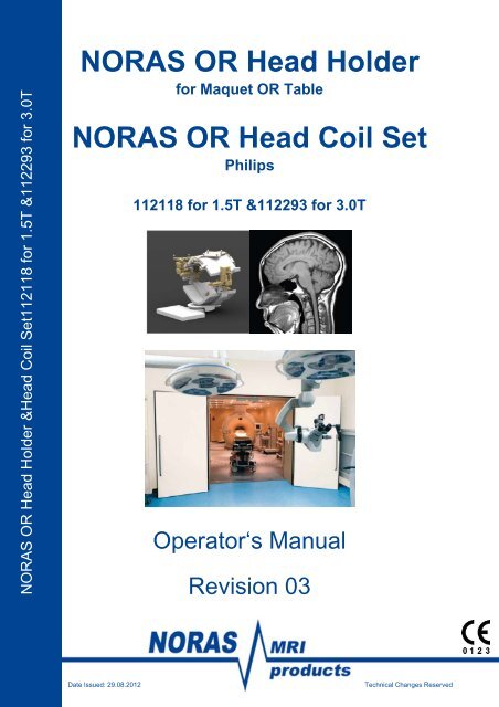
Manual 8 Ch Head Holder, Rev.3 PHILIPS - NORAS MRI products ...
Manual 8 Ch Head Holder, Rev.3 PHILIPS - NORAS MRI products ...
Manual 8 Ch Head Holder, Rev.3 PHILIPS - NORAS MRI products ...
You also want an ePaper? Increase the reach of your titles
YUMPU automatically turns print PDFs into web optimized ePapers that Google loves.
Content5.3.5 Performing the MR Imaging ............................................................... 5-385.3.6 After the Pre-Operative Scan ............................................................. 5-385.4 Sterile OR-Area ........................................................................................ 5-395.4.1 Sterile OR-Area .................................................................................. 5-395.4.2 Sterile <strong>NORAS</strong> OR <strong>Head</strong> <strong>Holder</strong> ........................................................ 5-395.4.3 Sterile Clamps .................................................................................... 5-405.4.4 Sterile OR-Area .................................................................................. 5-405.5 Intra-Operative Scan ................................................................................ 5-415.5.1 Removing Non MR-Compatible Parts ................................................ 5-415.5.2 Mounting of the Top Array Coil .......................................................... 5-415.5.3 Cover all sterile .................................................................................. 5-425.5.4 Patient Transfer and Intra-Operative Scan ......................................... 5-425.5.5 Perform Scan and Transfer back to the OR-Table ............................. 5-435.5.6 Continue Intervention ......................................................................... 5-436 Coil Maintenance & Troubleshooting .............................................................. 6-446.1 <strong>NORAS</strong> OR <strong>Head</strong> Coil Maintenance ........................................................ 6-446.1.1 Phantom Positioning .......................................................................... 6-446.1.2 <strong>NORAS</strong> OR <strong>Head</strong> Coil Positioning ..................................................... 6-456.2 Troubleshooting ........................................................................................ 6-466.3 <strong>NORAS</strong> OR <strong>Head</strong> <strong>Holder</strong> Maintenance .................................................... 6-467 Accessories .................................................................................................... 7-477.1 Pediatric Set ............................................................................................. 7-517.1.1 The Pediatric Set consists of .............................................................. 7-517.1.2 Intended Use of the Pediatric Set ...................................................... 7-517.1.3 The Pediatric One-Point-Fixation ....................................................... 7-527.1.4 Multi-<strong>Ch</strong>amber-Vacuum Cushion ....................................................... 7-537.1.5 Using the Pediatric Set ....................................................................... 7-547.2 The LEYLA-Retractor Socket ................................................................... 7-567.3 VarioGuide Adapter .............................................................................. 7-577.4 Sugita ® Adapter Set .................................................................................. 7-587.5 Ring .......................................................................................................... 7-607.6 BrainLab Navigation System .................................................................... 7-617.6.1 Navigation Socket .............................................................................. 7-617.6.2 BrainLab TREGS ............................................................................... 7-627.7 Adapter Set for Large Pins ....................................................................... 7-63Page 3
Content8 Cleaning, Disinfection and Sterilizing ............................................................. 8-659 Maintenance, Storage and Waste Disposal .................................................... 9-729.1 Maintenance ............................................................................................. 9-729.2 Storage ..................................................................................................... 9-729.3 Waste Disposal ......................................................................................... 9-7210 Technical Specification .............................................................................. 10-7310.1 Device Data ......................................................................................... 10-7310.2 Performance Data ............................................................................... 10-7311 Operator Training Outline .......................................................................... 11-7412 Declaration of Conformity .......................................................................... 12-7713 EC Declaration according to Article 12 ...................................................... 13-78Page 4
Notes1 Notes1.1 Manufacturer’s NotesThis product bears a CE marking in accordance with the provisions of regulation93/42 EEC of June 14, 1993 and council directive 2007/47 of September 05, 2007 formedical <strong>products</strong>.The CE marking applies only to medico-technical <strong>products</strong>/medical <strong>products</strong>introduced in connection with the above-mentioned comprehensive EC regulation.This operator’s manual is a supplement to the system manuals for ACHIEVA <strong>MRI</strong>SYSTEM 1.5T and 3.0T series and the Maquet Transfer Board system.This product subjected to FDA premarket notification K093693 on Jan 19, 2010.This product holds the following licensees from Health Canada on Sep 29, 2009:<strong>NORAS</strong> OR <strong>Head</strong> <strong>Holder</strong> 80767<strong>NORAS</strong> OR <strong>Head</strong> Coil 1.5T/3.0T 80766<strong>NORAS</strong> <strong>MRI</strong> <strong>products</strong> GmbHLeibnizstraße 497204 HoechbergGermanyTel.: +49 931 29927-0Fax: +49 931 29927-20info@noras.dewww.noras.dePage 1-5
Notes1.2 General NotesProper, safe operation of ACHIEVA 1.5T and 3.0T <strong>MRI</strong> high field systems requirestechnical knowledge of the operating personnel and a high degree of familiarity withthe operator’s manual.Prior to using the <strong>NORAS</strong> OR <strong>Head</strong> <strong>Holder</strong> and the <strong>NORAS</strong> OR <strong>Head</strong> Coil 1.5T /3.0T, this operator’s manual, as well as the system manual of your ACHIEVA <strong>MRI</strong>systems 1.5T and 3.0T series, needs to be read in detail.The <strong>NORAS</strong> OR <strong>Head</strong> <strong>Holder</strong> and the <strong>NORAS</strong> OR <strong>Head</strong> Coil 1.5T / 3T can only beused in combination with the Maquet Transfer Board. As a result, all safetyinformation in the ‘Philips’ operator’s manual have to be applied for the <strong>NORAS</strong> OR<strong>Head</strong> <strong>Holder</strong> and the <strong>NORAS</strong> OR <strong>Head</strong> Coil 1.5 / 3T as well.Male and female patients are referred to as ‘the patient’ for simplicity.References to ‘Philips service’ include service personnel authorized by Philips.References to ‘<strong>NORAS</strong> service’ include service personnel authorized by <strong>NORAS</strong>.From a technical point of view there is no limitation of the useful life, if the describedmaintenance is performed (instructions for use, cleaning, disinfection and sterilizationas well as maintenance and storage of the system components).The use of other medical devices is the responsibility of theuser as long as it has not been announced from manufacturer.Page 1-6
Notes1.3 Warning and Safety InstructionsWarning and safety instructions are especially labeled as such; the following signalsindicate the level of risk:Warning regarding risks that may result in death or seriousphysical injury.Warning regarding risks that may result in minor physical injuryor material damage.Information regarding the optimal use of the <strong>NORAS</strong> OR <strong>Head</strong><strong>Holder</strong> and <strong>NORAS</strong> OR <strong>Head</strong> Coil.iInformation provided to facilitate tasks for the user.Page 1-7
NotesUnacceptable handling of the <strong>NORAS</strong> OR <strong>Head</strong> <strong>Holder</strong> andthe <strong>NORAS</strong> OR <strong>Head</strong> Coil 1.5T/3.0TTo avoid injuries of the patient:- Ensure that the <strong>NORAS</strong> OR <strong>Head</strong> <strong>Holder</strong> and the<strong>NORAS</strong> OR <strong>Head</strong> Coil are used by trained staff only.- Ensure that staff adheres to the safety information.- Train all staff with the respect to the safety and warninginformation.- The system should only be operated by clinical stafftrained with respect to magnetic field hazard.- Assign a staff member to monitor all ferromagnetic andmagnetically materials.- Make sure your staff members read and sign a copy ofthe pages ’Operator Training Outline’ located in chapter11 of this operator’s manual.For safely fixation of head, especially in case of a small sizehead, the big Pin <strong>Holder</strong>s (medium/long) must be used. Theusers have to ensure that all five points are being in contactwith the skull. Failure to comply may result in head injury, falsedetection of marker and lesion and/or reduced diagnostic safety.Damage of the device- Handling error can cause permanent damages of thedevice.- Improper cleaning, disinfection and sterilization cancause permanent damages of the device. Please noticechapter 8 ‘Cleaning, Disinfection and Sterilizing’ of thisoperator’s manual.Page 1-8
Notes1.4 Personal Safety InformationFerromagnetic/magnetically objects become missiles!To avoid injuries of the patient, make sure that instruments andtools (such as clamps, spatulas and clips) have been removedfrom (within) the patient and the <strong>Head</strong> <strong>Holder</strong> before moving thepatient into the magnet.Reduced diagnostic safety!To avoid reduced image quality, make sure that all skull pins areas far as possible away from the operation center.Slippage of the head!To avoid injuries of the patient, the skull pins should be visuallyinspected and must be replaced in case they are dull and / orworn out.The pins injure the skull!The surgeons must be warned that an injury of the patientcannot be excluded, while the pins are located on the skull. Theuser bears the responsibility for using other devices such asdefibrillators while the head is fixed in the <strong>Head</strong> <strong>Holder</strong>.Improper use!To avoid injuries of the patient, the surgeons must be warnedthat harm to the body cannot be excluded if the skull pins arenot used probably. The surgeons must ensure by a control scanthat after the opening of the skull, the position of the fiducialsand lesion have not been substantially changed.Page 1-9
NotesThe Bottom Array is not fixed!To avoid reduced image quality, tighten the screws for coilfixation properly (only hand-tight).Connection cable is not plugged in correctly in the coil!To avoid reduced image quality or electronically damages of thecoils, create a proper connection between all plugs of cables,coils and scanner. Do not clamp any drapes or covers.Upper part of the <strong>NORAS</strong> OR <strong>Head</strong> Coil is not fixed!To avoid reduced image quality, use the third connection pin ofthe upper part of the <strong>NORAS</strong> OR <strong>Head</strong> Coil.Damage of the coil!To avoid malfunction, do not move the unconnected coil with theopen-ended connector toward the imaging area during theimaging.Reduced patient safety!After the exchange of an anterior coil, a reference scan has tobe performed.Page 1-10
NotesDamage of the coil!To avoid reduced patient safety, the operator must be able toread and understand the manual with all its warnings andcaution statements.Staff is not trained!To avoid reduced patient safety, the staff has to be trained. Thetraining will be provided with initial delivery of the <strong>NORAS</strong> OR<strong>Head</strong> Coil / <strong>Head</strong> <strong>Holder</strong>.Staff is not trained!To avoid reduced patient safety, please read the operator’smanual.Improper cleaning!To avoid reduced patient safety, please read the operator’smanual for cleaning instructions.To avoid reduced patient safety, do not submerge the coils andcables in water.Page 1-11
NotesAdviceThe physician is responsible for all ferromagnetic/magneticallyinstruments and tools which are used in the MR room (Pleaseobserve the operator’s manual for the MR imaging system).<strong>NORAS</strong> <strong>MRI</strong> <strong>products</strong> GmbH recommends not usingferromagnetic/magnetically instruments and tools for safetyreasons.During the operation, all ferromagnetic/magneticallyinstruments and tools have to be monitored by a designatedstaff member and removed completely before moving thepatient into the magnet.Ear protection for patientsPatients under anesthesia or those rendered unconscious haveto be provided with ear protection.Eye protection for patientsNormally the eyes are sufficiently protected by the naturalblinking reflex of the eyelids.Anesthetized patients or those who do not have a blinkingreflex for any reason must be protected from the laser beam.Hazard during pregnancyTo date, there is no scientific proof that MR examinations areharmless for pregnant women or that RF exposures areharmless for pregnant operating staff.Page 1-12
NotesLegal regulations governing exposure of personnelExposure of staff to static magnetic fields and noise may beregulated by local law.<strong>Ch</strong>ronic exposure to magnetic fieldsThe biological effects of long term exposure times are notdetermined yet.Comply with limits established for exposure to magnetic fields.Material damageIn order to prevent from any damages due to improper cleaningprocedures, please strictly observe chapter 8 ‘Cleaning,Disinfection and Sterilizing’, especially regarding the allowedcleaning temperatures.Page 1-13
General2 General2.1 Intended UseThe <strong>NORAS</strong> OR <strong>Head</strong> <strong>Holder</strong> and <strong>NORAS</strong> OR <strong>Head</strong> Coil 1.5T / 3T are used forintra-operative MR imaging during open-skull neurosurgery.The <strong>NORAS</strong> OR <strong>Head</strong> <strong>Holder</strong> is used for safely securing the patient‘s head duringthe intervention.In addition, the <strong>NORAS</strong> OR <strong>Head</strong> Coil 1.5 / 3T can be mounted to allow imaging ofthe patient‘s head during the intervention. Imaging can be done with the ACHIEVA1.5T or 3.0T <strong>MRI</strong> System series depending on the relevant <strong>NORAS</strong> OR <strong>Head</strong> Coil.The bottom array of the <strong>NORAS</strong> OR <strong>Head</strong> Coil 1.5T / 3T is mounted to OR <strong>Head</strong><strong>Holder</strong> to secure the head.The top array of the <strong>NORAS</strong> OR <strong>Head</strong> Coil 1.5T / 3T is used only while performingMR imaging and is removed during the intervention to allow the best possible accessto the area of intervention.The <strong>NORAS</strong> OR <strong>Head</strong> <strong>Holder</strong> (113066) and the <strong>NORAS</strong> OR <strong>Head</strong> Coil 1.5T / 3T aresuitable for use with the following <strong>MRI</strong> systems:ACHIEVA <strong>MRI</strong> System 1.5T or 3.0T2.2 FunctionThe <strong>NORAS</strong> OR <strong>Head</strong> <strong>Holder</strong> and the <strong>NORAS</strong> OR <strong>Head</strong> Coil 1.5T / 3.0T combinethe functions of a head holder for neurosurgical interventions and an MR receivingcoil for intra-operative surgery.The <strong>NORAS</strong> OR <strong>Head</strong> <strong>Holder</strong> without the <strong>NORAS</strong> OR <strong>Head</strong> Coil 1.5T / 3.0T can beused for stabilizing the patient’s head. It can also be used in combination with thebody coil.The C-Arc of the <strong>NORAS</strong> OR <strong>Head</strong> <strong>Holder</strong> allows adjustment to heads varying in size.For optimal access to the area of intervention, the C-Arc can be swiveled and rotated.2.3 IndicationThe <strong>NORAS</strong> OR <strong>Head</strong> <strong>Holder</strong> and <strong>NORAS</strong> OR <strong>Head</strong> Coil 1.5T / 3.0T are used forintra-operative MR imaging during open-skull neurosurgery.The <strong>NORAS</strong> OR <strong>Head</strong> <strong>Holder</strong> is used for safely securing the patient‘s head duringthe intervention.Page 2-14
General2.4 ContraindicationAll patient examinations are contraindicated with the system which is alsocontraindicated in the proximity of the <strong>MRI</strong> device according to the informationprovided by the manufacturer (e.g. heart pacemakers, surgical metallic implants orsimilar objects).Furthermore, the responsibility lies with the examining physician in case of an unclearor critical clinical situation.Page 2-15
Installation3 <strong>NORAS</strong> OR <strong>Head</strong> <strong>Holder</strong>& 1.5T/3.0T <strong>Head</strong> Coil SetCable C3 Bottom Array 3.0T: 1134181.5T: 112662Cable C3 Top Array 3.0T: 1134191,5T: 112661Top Array PH 3.0T: 114557 7210-PH1.5T: 111921 7110-PHIllustrative purpose only1.5T & 3.0T 113066 SI7000-MQLabel on Base PlateBottom Array PH 3.0T: 114558 7220-PH1.5T: 111922 7120-PHPage 3-16
Installation3.1 Components of the <strong>NORAS</strong> OR <strong>Head</strong> <strong>Holder</strong> for Maquet OR Table113391113410112964112785112008112708113065113064113069113049113048112996112845111885112847112939112847112277111884113063113037113010112701112932113055Illustrative purpose onlyPage 3-17
InstallationPicture Qty Part No.New/Old1 113066SI7000-MQPart Name<strong>Head</strong>-<strong>Holder</strong>MaquetLabeling(Sample)1 113063SI7001-MQ4 113069SI7030-MQ1 113064SI7030-MQW1 113055SI7015Base plate forMaquet TransferBoard(Lable for whole<strong>Head</strong> <strong>Holder</strong> onbottom of baseplate)Screw forMaquet TransferBoardTool for MaquetTransfer BoardscrewsC-Arc holdern/an/an/a1 111885SI7002Screw for Ball-Jointn/a1 111884SI7003Nut for Ball-Jointn/a1 113065SI7041Wrench for Ball-Jointn/aPage 3-18
InstallationPicture Qty Part No.New/Old1 112939SI7004C-ArcPart NameLabeling(Sample)3 111855SI7005Screw for C-Arcn/a2 112708 Clamp, left n/a2 112932 Clamp, right n/a2 113410 Column n/a1 113391 Coil FixationPlaten/a2 112701 Block n/a2 113010 Coil FixationSpacern/a9 113049SI7007Screw for clampn/a9 113037 Multipurposescrewn/aPage 3-19
InstallationPicture Qty Part No.New/Old1 112785SI79031 113054SI7016Part NameTwo-Point-FixationcompleteSquare retainerLabeling(Sample)n/an/a1 112964SI7009Pin retain screwn/a1 112008SI7014Adjustment nutn/a2 112845 Pin <strong>Holder</strong> small n/a2 112847 Pin <strong>Holder</strong>mediumn/a2 112852 Pin <strong>Holder</strong> large n/a1 112728 Drape LinkAdaptern/a10 112277SI6018Titanium skullpin, big tipn/a1 113048SI70475-bolt wrenchwith ball gripn/a2 112996SI60075-boltwrench,smalln/a1 113168SI7057Thread cleanerM6, not MRcompatiblen/aPage 3-20
Picture Qty Part No.New/OldInstallationPart NameLabeling(Sample)1 113027 Foliodrape n/a1 113198 Back cushionMaquet TransferBoard1 113197 Seat cushionMaquet TransferBoardn/an/a6 112771 Cable fixation n/a1 113598SI7444Phantom-<strong>Holder</strong>n/a1 n/a Phantom Bottle.Not part ofdelivery.Order at Philips:Phantom Bottle5000 CC 3T4522 131 956201 112544 Operator’smanualn/an/aPage 3-21
Installation3.2 Components of the <strong>NORAS</strong> OR <strong>Head</strong> Coil 1.5TPicture Qty Part No.New/Old1 1119217110-PHPart NameTop Array1.5TLabeling(Sample)1 1119227120-PHBottom Array1.5T1 112661 Connectorcable for toparray coil 1.5T1 112662 Connectorcable forbottom arraycoil 1.5TPage 3-22
Installation3.3 Components of the <strong>NORAS</strong> OR <strong>Head</strong> Coil 3.0TPicture Qty Part No.New/Old1 1145577210-PHPart NameTop Array3.0TLabeling(Sample)1 1145587220-PHBottom Array3.0T1 113419 Connectorcable for toparray coil 3.0T1 113418 Connectorcable forbottom arraycoil 3.0TAdditional labeling for all coils 1.5T and 3.0T(Sample)Warning Label ‘Do NOT submerge in water’Page 3-23
Installation4 Installation of the <strong>NORAS</strong> OR <strong>Head</strong> <strong>Holder</strong> and <strong>NORAS</strong> OR <strong>Head</strong>Coil4.1 Base Plate Installation on the Maquet Transfer BoardFor the installation the Maquet Transfer Board must be positioned on the Maquet ORtable. Please read the manual of the Maquet OR table, too!The next pictures show the installation of the <strong>NORAS</strong> OR <strong>Head</strong> <strong>Holder</strong>.Page 4-24
Installation4.2 Installation of C-Arc <strong>Holder</strong> and C-ArcAttach the C-Arc <strong>Holder</strong> to thebase plate by using the screwand nut for the ball joint. Fix ithand-tight by using thewrench for ball-joint113065(picture)oralternatively the wrench forball-and-socket-joint113047(see Accessories)Mounted C-Arc <strong>Holder</strong>Attach the C-Arc to the C-Arc<strong>Holder</strong>Fix it with two screws 111855 by using the 5-bolt wrench with ball grip 113048Cover transfer board with Back cushion 113198Wobble of the <strong>NORAS</strong> OR <strong>Head</strong> <strong>Holder</strong>The screws have to be strongly tightened to OR table top.The screws have to be strongly tightened at each joint. This isthe only way to achieve a proper functionality of the <strong>NORAS</strong> OR<strong>Head</strong> <strong>Holder</strong> and the safety of the patient.Improper installation of the base plateAttach the base plate of the <strong>NORAS</strong> OR <strong>Head</strong> <strong>Holder</strong> to theMaquet Transfer Board using four plastic screws and the tool forMaquet Transfer Board screws to avoid any movement of theplate.Page 4-25
Installation4.3 Assembling the C-ArcPlease install the C-Arc on the mounted base plate before performing these steps.1 2 3Attach the lower Pin<strong>Holder</strong>s (small, medium,large)Attach the Two-Point-FixationAttach the One-Point-Fixation4 5 6Put patient’s head in the<strong>Head</strong> <strong>Holder</strong> and adjustPin <strong>Holder</strong>s, but withoutScull PinsLift head, insert all fiveScull Pins into the holdersLet the head sink ontothe lower Scull Pins.TheScull Pins penetrate theskullPage 4-26
Installation7 8 9Adjust the Two-Point-Fixation on the head untilthe Scull Pins touch theskull, tighten adjustmentnutsTighten the two fixationscrews left and right toreduce play of One- andTwo-Point-FixationClamp head with theOne-Point-Fixation andre-adjust the lower ScullPins(lift max. 10mm fromlowest position for largeand medium pin holdersbut only max. 5mm forsmall pin holders)10 11 12Perform interventionCover all sterile Mount two sterile clamps Perform interventionPlease find additional information to the optional accessories in chapter 7‘Accessories’.Page 4-27
InstallationInjury to patient during the surgeryThe fixation screws have to be tightened strongly, but only byhand (see picture 8 above). Visual inspection is needed (no gapbetween angle brackets and Two-Point-Fixation bar and squareretainer).Notice: Click only at compensator!Visual inspection of the Two-Point-Fixation rod must beperformed before each surgery. This is necessary due topossible wear and tear of the Two-Point-Fixation rod.Staff is not trainedEnsure that all staff is trained with the respect to OR <strong>Head</strong><strong>Holder</strong> / OR <strong>Head</strong> Coil and magnetic field hazards to guaranteepatient safety.Page 4-28
Installation4.4 Installation of the <strong>NORAS</strong> OR <strong>Head</strong> CoilThe <strong>NORAS</strong> OR <strong>Head</strong> <strong>Holder</strong> must be installed before starting the installation of the<strong>NORAS</strong> OR <strong>Head</strong> Coils.1 2 3Cover all with one layer ofsterile drape, use asecond sterile drape todouble-cover the sterileclampsMount right coil holder, besure that there are twolayers of sterile drapebetween the holder andthe sterile clampsMount left coil holder, besure that there are twolayers of sterile drapebetween the holder andthe sterile clamps4 5 6Mount the top array coil tohighest positionAdjust the top array coil tothe lowest possiblepositionMaximum position is 30 !Tighten all multipurposescrews by hand7 8 9Connect cables to top andbottom coilCover whole setup withsterile coverTransfer to MR andperform scanPage 4-29
InstallationCoil is not stabilizedIf the coil is not stabilized, the quality of the intervention will bereduced. Ensure that all screws are hand-tightened.AdviceFor best image quality adjust the <strong>NORAS</strong> OR <strong>Head</strong> Coilparallel to the bore by adjusting the Ball-Joint of the <strong>NORAS</strong>OR <strong>Head</strong> <strong>Holder</strong>.AdviceFor best image quality, install the top array of the <strong>NORAS</strong> OR<strong>Head</strong> Coil on the lowest possible position.Damaged coil Do not use damaged coils to guarantee patients’ safety. Treat the coil with great care to avoid damages. Read the instruction of cleaning, disinfecting andsterilizing to avoid damages.Injury of the Patient!Prior to each patient examination, a visual inspection of allcomponents is mandatory. In case of unusual findings and /ordamage, the OR <strong>Head</strong> <strong>Holder</strong>/OR <strong>Head</strong> Coil must not be used.Damaged parts can be sharp-edged and can cause injuries tothe patient and/or the user. Do not use damaged coils and donot produce images with a defective coil.Page 4-30
Intervention Workflow5 Intervention WorkflowThe following chapter describes the workflow of the <strong>NORAS</strong> OR <strong>Head</strong> <strong>Holder</strong> and<strong>NORAS</strong> OR <strong>Head</strong> Coil.You can also use the <strong>NORAS</strong> OR <strong>Head</strong> <strong>Holder</strong> without the <strong>NORAS</strong> OR <strong>Head</strong> Coil.5.1 Adjustment of the <strong>NORAS</strong> OR <strong>Head</strong> <strong>Holder</strong>The <strong>NORAS</strong> OR <strong>Head</strong> <strong>Holder</strong> and bottom array of the <strong>NORAS</strong> OR <strong>Head</strong> Coil aremounted onto the Maquet Transfer Board. The tranferboard is fixed on the MaquetOR table.5.1.1 RotationAdjust the C-Arc on the C-Arc holder into desired angle.5.1.2 Ball-JointAfter loosen the nut of the Ball-Joint, you can move the C-Arc in the direction youprefer. Please keep in mind that you achieve best image quality when the <strong>NORAS</strong>OR <strong>Head</strong> Coil is parallel to the MR-bore. Also consider that the OR table top (with allattached parts) as well as the patient has to fit into the bore. After placing the patientin the final position, it is necessary to tighten the nut for Ball-Joint with a wrench113047 / SI5029 or optional 113065 / SI7041.Injury to patient during surgeryTo ensure the safety of the patient, make sure that the OR tabletop with the <strong>NORAS</strong> <strong>Head</strong> <strong>Holder</strong> and <strong>NORAS</strong> <strong>Head</strong> Coil fit intothe MR bore. Also tighten all nuts and screws securely.Injury to patient during surgeryTo ensure the safety of the patient, make sure that all screwsare tightened strongly on the each individual hinge. Screwsshould only be tightened by hand or with the <strong>NORAS</strong> tools. Noother tools are to be used!Page 5-31
Intervention Workflow5.2 Fixation of the <strong>Head</strong>The <strong>NORAS</strong> OR <strong>Head</strong> <strong>Holder</strong> is mounted and adjusted.5.2.1 ClampsMount two clamps onto the C-Arc and tighten the screws for the clamps with a 5-boltwrench.5.2.2 Pin <strong>Holder</strong>sScrew two Pin <strong>Holder</strong>s to the lowest possible position onto the bolts of the C-Arc.You have three different sizes available: small, medium, and large.5.2.3 Patient Positioning (Part I)Hold the patient’s head in the <strong>NORAS</strong> OR <strong>Head</strong> <strong>Holder</strong> and pre-adjust the two lowerPin <strong>Holder</strong>s, the Two-Point-Fixation and the pin retain screw. Make sure that youleave enough space for the positioning of the head. You have to do this step firstwithout the Skull Pins to ensure you chose the right position.Page 5-32
Intervention WorkflowAdviceAlways consider life supporting arrangements during theoperation and the scanning.Page 5-33
Intervention Workflow5.2.4 Patient Positioning (Part II)Raise the head slightly out of the <strong>NORAS</strong> OR <strong>Head</strong> <strong>Holder</strong> and place all five titaniumSkull Pins. Lower the patient’s head slowly on top of the two lower Skull Pins and fixthe head into these Skull Pins as soon as you have found the right head position.Then fix the head by using the Two-Point-Fixation device. Finally, apply pressure tothe head with the One-Point-Fixation. You can alternatively use the One-Point-Fixation 113061/SI7044.Afterwards, it is very important and absolutely crucial to re-tighten the two lower SkullPins.Worn or dull titanium Skull PinsWorn or dull titanium Skull Pins might cause injury to the patient.The titanium Skull Pins must regularly undergo a visualinspection. In case the titanium Skull Pins are worn and / or dull,they must be replaced.Insufficient quality imagingTitanium Skull Pins might cause artifacts. To avoid this, theymust be placed as far as possible out of the field of view (FOV).Page 5-34
Intervention Workflow5.3 Pre-operativeScanUnsterile scan before surgery, head is not open!5.3.1 Coil AssemblyAttach two unsterile clampsMount two coil holders onto the clampsPage 5-35
Intervention WorkflowMount the Top Array Coil to the lowest possible positionAdviceFor optimal image quality, fix the Top Array Coil of the <strong>NORAS</strong>OR <strong>Head</strong> Coil always on the lowest possible position. Bestimage quality will be achieved in Ø-position. In case you chosea higher position, adjust the top array of the <strong>NORAS</strong> OR <strong>Head</strong><strong>Holder</strong> the same way for the intra-operative scan. The scale ofthe coil holder shows you the chosen position.Permanent damageOperator errors could cause permanent damage to the device.Page 5-36
Intervention Workflow5.3.2 Removing non MR-Compatible PartsPrior to each scan with the MR-System, you have to remove all non MR-compatibleparts. This could be clamps, scalpels, <strong>NORAS</strong> accessories such as the VarioGuideAdapter, Sugita ® Adapter or others.Top Array Coil of the <strong>NORAS</strong> OR <strong>Head</strong> Coil is not fixedTo avoid reduction of quality of intervention:Use both coil holders for height adjustment Hand-tighten all multipurpose screws until they aresecured.Staff is not trainedEnsure that all staff is trained with respect to magnetic fieldhazards.5.3.3 Patient TransferFor patient transfer and scanning, please observe the operator’s manual of the ORtable.Out sticking partsIn order to avoid injuries to the patient during the scan, payattention that the <strong>NORAS</strong> OR <strong>Head</strong> <strong>Holder</strong> fits into the MR bore.Page 5-37
Intervention Workflow5.3.4 Cable GuidingWhen the patient is on the <strong>MRI</strong> system, plug-in the unsterile cable into the unsterilebottom array of the <strong>NORAS</strong> OR <strong>Head</strong> Coil and the <strong>MRI</strong> system. Install the cable onthe cable holders on the mattress, then guide the cable over the patient and plug it inthe <strong>MRI</strong> system. Afterwards plug in the unsterile cable into the top array of the<strong>NORAS</strong> OR <strong>Head</strong> Coil. Fix the cable beginning on the cable holders on the mattressand plug it in the <strong>MRI</strong> system. Be careful that no cables get loose during moving thepatient into the system. Use the light visor to move the coil into the ISO center.Perform your scan by using the Philips manual.Worse electric contact to the <strong>MRI</strong> scanner!To avoid reduced quality of the intervention check the plugs and socket of the top array of the<strong>NORAS</strong> OR <strong>Head</strong> Coil check the plug and the socket of the bottom array of the<strong>NORAS</strong> OR <strong>Head</strong> Coil5.3.5 Performing the MR Imaging Connect the cable of the bottom array to the appropriate table socket.Connect the cable of the top array to the appropriate table socket.Center the <strong>NORAS</strong> OR <strong>Head</strong> Coil into the ISO center.Perform the MR imaging.Please observe the scanner manual for the MR imaging procedure.5.3.6 After the Pre-Operative Scan Unplug the connection cables from the table sockets.Transfer the patient back to the OR table.Loosen the multipurpose screws for the top array on the clamps. Write down the values of the scales on the coil holder to have the sameintra-operative coil setup (= distance between the coils) anytime. Remove the Top Array Coil of the <strong>NORAS</strong> OR <strong>Head</strong> Coil by pulling itupward.Page 5-38
Intervention Workflow Remove the two clamps from the <strong>Head</strong> <strong>Holder</strong>. The removed parts cannow be sterilized for the next operation. Please observe chapter 8‘Cleaning, Disinfection and Sterilizing’.5.4 Sterile OR-Area5.4.1 Sterile OR-AreaCover the OR-area sterile, for example with sterile drape.5.4.2 Sterile <strong>NORAS</strong> OR <strong>Head</strong> <strong>Holder</strong>Cover the OR-area and the <strong>NORAS</strong> OR <strong>Head</strong> <strong>Holder</strong> sterile with a sterile drape or aplastic foil. While covering with sterile material, use only one layer of cloth or plasticfoil on top of the <strong>NORAS</strong> OR <strong>Head</strong> <strong>Holder</strong>.Page 5-39
Intervention Workflow5.4.3 Sterile ClampsMount two sterile clamps. This is done by penetrating the drape or the plastic foil withthe screws (for the clamps) onto the C-Arc. Tighten the screws with a sterile 5-boltwrench.Unsterile partsUse only sterile parts during each intervention. Do not reuse theparts from the pre-operative scan.Clamps are fixed inadequatelyWhile mounting the clamps, straighten the sterile cloth andscrew it tightly onto the clamps.The Top Array Coil of the <strong>NORAS</strong> OR <strong>Head</strong> Coil is not fixedTo avoid reduced quality of the intervention, please tighten allscrews by hand or appropriate <strong>NORAS</strong> tool until they aresecured. Do not use brute force or any other tools.5.4.4 Sterile OR-AreaNow you have a sterile area over the cover and an unsterile area under the coverand you can start your intervention. You can mount different accessories onto the twosterile clamps, such as the LEYLA-Retractor socket or other customized parts, whichyou can find in chapter 7 ‘Accessories’.Page 5-40
5.5 Intra-Operative ScanIntervention Workflow5.5.1 Removing Non MR-Compatible PartsPrior to each scan with the MR-System, you have to remove all non MR-compatibleparts. This could be clamps, scalpels, <strong>NORAS</strong> accessories such as the VarioGuideAdapter, Sugita ® Adapter or others.5.5.2 Mounting of the Top Array Coil1 2 3Cover all with one layerof sterile drape, use asecond sterile drape todouble – cover thesterile clampsMount right coil holder, besure that there are twolayers of sterile drapebetween the holder and thesterile clampsMount left coil holder, besure that there are twolayers of sterile drapebetween the holder andthe sterile clamps4 5 6Mount coil to the highestpositionAdjust coil to the lowestpossible positionMaximum position is 30 !Tighten all multipurposescrews by handPage 5-41
Intervention WorkflowAdvicePlace the Top Array Coil of the <strong>NORAS</strong> OR <strong>Head</strong> Coil in thesame parallel position as the coil from the pre-operative scanby using the scales on the coil holder.For best image performance, install the Top Array Coil of the<strong>NORAS</strong> OR <strong>Head</strong> Coil always on the lowest possible position.Best image quality will be achieved in Ø-position.5.5.3 Cover all sterilePlace a cover over the complete setup before the patient is transferred.5.5.4 Patient Transfer and Intra-Operative ScanFor patient transfer within the same facility and scanning, please observe theoperator manuals of the OR table and scanner.Protruding partsTake care that the <strong>NORAS</strong> OR <strong>Head</strong> <strong>Holder</strong> fits into the MRbore to avoid injury to the patient during the scan.Page 5-42
Intervention Workflow5.5.5 Perform Scan and Transfer back to the OR-TableAfter the scan, disconnect both long cables from the <strong>MRI</strong> system and fix the cable onthe feet side of the Maquet Transfer Board. Move the patient out of the MR bore.Transfer the patient back to the OR table by referring to your Philips and Maquetmanuals.Remove the Top Array Coil and the coil holders. Remove the two drapes and checkthem for holes! If there would be holes you have to cover the clamps with sterile tapeand finish the operation, the clamps are unsterile and may not be used anymore.5.5.6 Continue InterventionAfter the Top Array Coil has been removed, you can attach the sterile accessories tocontinue your operation. You find these in chapter 7 ‘Accessories’. You can gatheradditional MR-images by repeating the intra-operative scan procedure.Make an intra-operative scan to assure that the position of themarkers and the position of the lesion have not been changedsubstantially.Unsterile parts in the area of interventionUnsterile parts in the area of intervention could cause sepsis.Page 5-43
Coil Maintenance & Troubleshooting6 Coil Maintenance & Troubleshooting6.1 <strong>NORAS</strong> OR <strong>Head</strong> Coil MaintenanceWe recommend to test the <strong>NORAS</strong> OR <strong>Head</strong> Coil regularly. Your <strong>MRI</strong> systemprovides you with a coil check function. Please read your Philips manual.6.1.1 Phantom PositioningMount the <strong>NORAS</strong> OR <strong>Head</strong> <strong>Holder</strong> with the <strong>NORAS</strong> OR <strong>Head</strong> Coil as described inchapter 4 onto the Maquet Transfer Board. Place the phantom holder on the bottomarray of the <strong>NORAS</strong> OR <strong>Head</strong> Coil and the bottle phantom on the phantom holder asyou can see in the picture below.Page 6-44
Coil Maintenance & Troubleshooting6.1.2 <strong>NORAS</strong> OR <strong>Head</strong> Coil PositioningThe two screws which fix the height adjustment tongues represent the center of thecoil. Use the screws to find the middle position with the laser visor in order to bringthe coil into the ISO center.AdviceIf you are using the BrainLab ‘TREGS’, we recommend doingthe coil check with the mounted ‘TREGS’ system.In case the SPT coil check fails: The total SNR is in specified range, but one or more channels are belowspecification <strong>Ch</strong>eck the setup of the test carefully! Has the phantom been positioned in theright way? Run the test again. Save the SPT as a PDF and inform your local Philips service engineer serviceand <strong>NORAS</strong> by forwarding the PDF document. The coil can be still used for interventions but should be replaced as soon aspossible!The total SNR is below specification Save the SPT as a PDF and inform your local Philips service engineer serviceand <strong>NORAS</strong> by forwarding the PDF document. The coil should not be used for interventions any longer.Page 6-45
Coil Maintenance & Troubleshooting6.2 TroubleshootingIn case, the <strong>MRI</strong> system does not accept a coil during the procedure:Not accepted bottom coil: <strong>Ch</strong>eck cables and connectors Exchange cables and connectors Finish the intervention with the top array onlyNot accepted top coil: <strong>Ch</strong>eck cables and connectors Exchange cables and connectors <strong>Ch</strong>ange the sterile intermediate cable and check the acceptance again. Use the second sterile top (only possible when you have sterilized the first toparray coil)Perform the MR examination and finish the procedure.Inform your local Philips service engineer service and <strong>NORAS</strong> about the failure!6.3 <strong>NORAS</strong> OR <strong>Head</strong> <strong>Holder</strong> MaintenancePlease check each component of the <strong>NORAS</strong> OR <strong>Head</strong> <strong>Holder</strong> for damages such ascracks, wear off etc. If you find abnormalities, please stop using the <strong>NORAS</strong> OR<strong>Head</strong> <strong>Holder</strong> and inform <strong>NORAS</strong> by sending an email to info@noras.de.Material DamageIn order to prevent the <strong>NORAS</strong> OR <strong>Head</strong> <strong>Holder</strong> / <strong>Head</strong> Coilfrom any damages due to improper cleaning procedures,please strictly observe chapter 8 ‘Cleaning, Disinfection andSterilizing’, especially regarding the allowed cleaningtemperatures.Page 6-46
Accessories7 AccessoriesWe provide you with a large amount of accessories for your <strong>NORAS</strong> OR <strong>Head</strong> <strong>Holder</strong>and <strong>NORAS</strong> OR <strong>Head</strong> Coil to reach optimum performance. The following listprovides an overview. The accessories will be described later in this chapter.Picture Part No. Description113217 Multifunctional Bar SystemThrough the modular setup of toothed joint partsand bars, the bar system can be adjustedideally. GREENBERG retractors can bemounted onto the bars and Budde ® Haloretractors can be clamped onto the joint parts.The ending of the joint parts is composed of aLEYLA-Retractor socket, which can be turnedand locked vertically in various angles.113218 Hand RestsAs the bar system, the hand rests can also bemounted in various angles. GREENBERGretractors can be mounted onto the bars andBudde ® Halo retractors can be clamped onto thejoint parts. The ball joints enable an idealadjustment of the hand rests for fatigue-proofoperation. Due to the large screws, werecommend to remove the hand rests before theMR-scan.112934 BrainLab InterfaceServes as basis for the previous BrainLabreference- array. Since this interface-type cutsthrough the sterile drapes, it is not suited for thecombination of automatic registration and thenew sterile concept. The base is toothed andcan be angled in head-foot direction.113219SI7342RingThe Ring can be mounted onto the toothing ofthe clamps in various angles.The scalp can be sewed onto the ring ormounted with rubber bands or hooks. Therefore,the skin can stay fixed and will not have to beundone before the MR-scans.Page 7-47
AccessoriesPicture Part No. Description111815 VarioGuide AdapterWith this adapter, the BrainLab VarioGuidecan be mounted on the left or right side of the<strong>Head</strong> <strong>Holder</strong>.113242SI7450Sugita ® Adapter SetThe steel angle brackets with screws enable theattachment of the aluminum basal frame thatcomes with the Sugita ® system. The adapter,including the ring, has to be removed beforeeach MR-scan.113220 All-Purpose ArchThe all-purpose arch can be attached in differentangles to the toothing of the clamps in head-footdirection. If mounted in foot direction, the scalpcan be sewed onto the arch or mounted withrubber bands or hooks. Therefore, the skin canstay fixed and will not have to be undone beforean MR-scan. If mounted in the front, the archserves as a hand rest or as an adapter of theretractor-rail of the Sugita ® .112986SI7341Additional FixationThe additional fixation can be attached to the‘clamp with joint’ in various angles. Therefore itis possible to attach various round bars to thefront side (for example Budde ® Halo orGREENBERG).The diameter of the fixation will be designedbased upon your requirements. (The pictureshows a sample with 8mm or 5/16 inch)Page 7-48
AccessoriesPicture Part No. Description113243 LEYLA-Retractor SocketThe socket serves as mount of the Sugita ®retractors. As before, the top part can be rotatedhorizontally in various angles. The new bottompart gets inserted into the dove tail of the <strong>Head</strong><strong>Holder</strong> and locked tightly.113314SI7916113047SI5029Adapter Set for Large PinsThe <strong>Head</strong> <strong>Holder</strong>s are delivered with smalltitanium pins, because titanium is autoclavable,break-proof and therefore re-usable. Since themount of metal of the small pins is very little, theresulting artifact is very small as well. Somecustomers, however, prefer disposable titaniumpins (due to their good ability to be refurbishedsterilely) or artifact-free ceramic pins foroptimized diffusion imaging. Because both ofthese pin types are only available with a largercollet, the <strong>Head</strong> <strong>Holder</strong> can be retrofitted to thislarger diameter with this pin adapter set.Furthermore, different change-inserts for smalland large heads can be inserted into the Two-Point-Fixation.Wrench for Ball-and-Socket-Joint113213 Pipe WrenchFor easier loosening of the One-Point-Fixationnuts or Two-Point-Fixation nuts.Page 7-49
AccessoriesPicture Part No. DescriptionSI7330Pediatric SetThe pediatric set has been developed in order tofulfill the requirements of pediatric demands. Itincludes a vacuum cushion, which replaces bothof the lower pins that cannot be used withchildren. Another component is a fixation-forcegauge with a hysteresis free ceramic spring,which provides accuracy between 0 to 70N. Thespring has been developed in collaboration withthe Frauenhofer Institute for ceramictechnologies and systems in Dresden, Germany(Frauenhofer Institut für KeramischeTechnologien und Systeme in Dresden,Germany). A set of 6 titanium pins with smalltips, like they are often in use for pediatricprocedures, is also included.Page 7-50
Accessories7.1 Pediatric SetTo be used with the <strong>NORAS</strong> OR <strong>Head</strong> <strong>Holder</strong>. The set enables the fixation of smallheads in the <strong>NORAS</strong> OR <strong>Head</strong> <strong>Holder</strong>.7.1.1 The Pediatric Set consists ofPicture Qty Part no. Part name1 SI7045 One-Point-Fixation child1 MR11002 Multi-chamber vacuum cushion1 MR11008 Vacuum hand pump6 (1 set) SI7323 Titanium skull pins, with small tip7.1.2 Intended Use of the Pediatric SetThe One-Point-Fixation is free of any metallic material. The titanium Skull Pin withsmall tip generates only a minimum of artifacts.The multi-chamber vacuum cushion enables the support from below the children’shead. It supports the head from the bottom and provides a first stabilization.The cushion is also designed for prone position and shows a horseshoe-form to easethe guidance of the life support tubes.Finally, the head will be fixed analog to the adult heads in the C-Arc, using specialSkull Pins to avoid perforation of the skull. The fixation of the skull is shown on thenext pages.Page 7-51
Accessories7.1.3 The Pediatric One-Point-FixationThe pediatric set comes along with a One-Point-Fixation for children to be usedinstead of the 112964 Pin retain screw. The One-Point-Fixation provides anorientation to the surgeon of the applied pressure.The scale is not calibrated!Maximum load:~ 60N, ~ 13, 4 lb fInjury to patient during surgeryPrior to conditioning and prior to application of the One-PointFixation to the skull, the user must ensure that the marked rodwhich intended for adaptation of skull pins protrudes about 10mm above the square screw. Otherwise, the user under thiscircumstance is not able to reach the desired pressure. If theuser still tries to turn the screw further, it is possible to damagethe square screw.The orientation for the applied pressure is not calibratedTo avoid injury to the patient: Make sure that the instrument is cleaned. Also, controlthe mobility of the pieces after each cleaning. It is strictly recommended to send the fixation device to<strong>NORAS</strong> once a year for quality control. During thistime, you can use the pin retain screw instead of theOne-Point-Fixation.Page 7-52
AccessoriesThe One- Point-Fixation cannot be steam sterilizedIt is not allowed to steam sterilize the One-Point-Fixation. Steamsterilization destroys the One-Point-Fixation.7.1.4 Multi-<strong>Ch</strong>amber-Vacuum CushionAfter evacuation, the cushion becomes hard but the head still has to be fixed withtitanium skull the pins.iInformationThe multi-chamber vacuum cushion is filled with small plastic balls. Thecushion is soft and flexible until it is evacuated with the hand pump.Page 7-53
Accessories7.1.5 Using the Pediatric SetThe pictures below are showing the fixation of a skull in the size of a ~ 6 month oldchild.Install the SI7045 One-Point-Fixation instead ofthe 112964 Pin Retain Screw.Place the cushion over the bolts of the C-Arc ofthe <strong>NORAS</strong> OR <strong>Head</strong> <strong>Holder</strong>.You can also place an MR-compatible gel padover the cushion.Place some soft textile between the head and thecushion to avoid skin irritations. The two topwings of the cushion have to be slid into thecenter or out of the center of the bottom coil,depending on the size of the child’s head.The head is positioned in the C-Arc and theTwo-Point-Fixation is set up properly. The One-Point-Fixation will be moved into position by theinterior adjustment nut.Page 7-54
AccessoriesWhen the head is lifted up into the right positionfor the fixation, evacuate the cushion. If the rightposition is reached, insert the titanium skull pinswith small tip. Bring the skull pin in contact withthe skin and fix the unit with both adjustment nutsproperly hand-tight.Adjust the appropriate pressure by turning thesetting bolt at the end of the unit. Observepressure indicator.As soon as ”stop” appears, the max. load of thedevice is achieved. Maximum load:~ 60 N ~ 13,4 lb f.The scale is not calibrated!The pediatric set comes along with six titaniumskull pins with small tips. The picture shows thetitanium skull pins with large tips on the left sideand the pins with small tips and wider shoulderon the right side.AdviceFor a pediatric case, three skull pins and a vacuum cushion arenecessary.For an adult case, a set of five skull pins is required at all times.Page 7-55
Accessories7.2 The LEYLA-Retractor SocketTo attach the LEYLA-Retractors to the clamps, use the LEYLA-Retractor socketbelow.Page 7-56
Accessories7.3 VarioGuide AdapterThe VarioGuide adapter enables the use of BrainLab’s VarioGuide arm inconjunction with the <strong>NORAS</strong> OR <strong>Head</strong> <strong>Holder</strong>. The VarioGuide and the adapterare in the sterile area during the surgery and must be removed before scanning.The picture below shows the VarioGuide adapter fitted to a clamp.VarioGuide arm and adapter must be removed beforescanning!If the scan must be repeated, the VarioGuide arm and adaptermust be removed completely before scanning, because theVarioGuide arm and adapter are magnetic.Page 7-57
Accessories7.4 Sugita ® Adapter SetThe Sugita ® adapter set enables the use of the Mizuho Sugita ® basal frame inconjunction with the <strong>NORAS</strong> OR <strong>Head</strong> <strong>Holder</strong>. The Sugita ® basal frame and theadapter set are in the sterile area during the surgery and must be removed beforescanning. The pictures below show the Sugita ® adapter set.Picture Qty Part No. Description2 SI7464 Screws for Sugita ® adapter, designed forthe Mizuho-Sugita ® screwdriver1 SI7460 Sugita ® adapter, left1 SI7461 Sugita ® adapter, rightThe Sugita ® basal frame and adapter set are magneticcomponents!!!MountingThe Sugita ® basal frame and adapter set must be removedbefore scanning. Hurtling parts could injure the patient. If thescan must be repeated, remove VarioGuide and Sugita ®adapter completely before scanning.1. Remove the basal frame from your Sugita ®Page 7-58
Accessories2. Mount the left and the right adapter with the original screws to the basal frame, donot tighten them. Drive in the two screws SI7464.The screws are designed that they will not fall off, even when they are loose. So youcan lift the basal frame with the adapters as one unit.3. Mount the basal frame with the adapters to the clamps with the additional fixation.Adjust the angles of the left and the right adapter in the same way and tighten allscrews with your Sugita ® screwdriver.Page 7-59
Accessories7.5 RingThe ring is designed to enable the fixation of fish hooks to keep the skin away fromthe trepanation.Picture Part No. DescriptionSI7355Clamp for Sugita ® cotton plate. This clamp can bescrewed to the ring.Page 7-60
Accessories7.6 BrainLab Navigation SystemThe <strong>NORAS</strong> OR <strong>Head</strong> <strong>Holder</strong> and <strong>NORAS</strong> OR <strong>Head</strong> Coil were developed to be usedtogether with the BrainLab Navigation System. Please find details in the BrainLabmanual.7.6.1 Navigation SocketThe C-Arc is equipped with two sockets for Navigation Systems, one at each side.Picture Part No. Description112728 Drape link adapter:Serves as basis for the BrainLab Drape-Link, which is needed to combineautomatic registration and the newsterile concept. The base is toothed andcan be angled in head-foot direction.112934 BrainLab Interface:Serves as basis for the previousBrainLab reference-array. Since thisinterface-type cuts through the steriledrapes, it is not suited for thecombination of automatic registrationand the new sterile concept. The base istoothed and can be angled in head-footdirection.Page 7-61
Accessories7.6.2 BrainLab TREGSThe BrainLab TREGS fiducials for automatic registration can be attached to the toparray coil.The use of other components as described and listed in thisoperator’s manual are not permitted.The handling of the device is only allowed by trained personnel.Make sure that staff members read and sign a copy of the page‘training information’ located in chapter 11 of this operator’smanual.Harm to the body due to accessoriesPlease follow the instructions of the accessory manufacturer.Non-compliance with these instructions may lead to injuries ofthe user and/or patient.Page 7-62
Accessories7.7 Adapter Set for Large PinsWith this adapter kit, using large ceramic skull pins from other manufacturers will bepossible. The four change insert plates with various arcs enable you to reach asufficient fixation of the head, even in case of abnormal head sizes.Picture Qty Part No. Part name1 7010-2 Two-Point-Fixation plate forchange insert1 7010-WE Two-Point-Fixation plate forchange insert adult1 7010-WEG Two-Point-Fixation plate forchange insert adult for large skullpins1 7010-WK Two-Point-Fixation plate forchange insert childPage 7-63
AccessoriesPicture Qty Part No. Part name1 7010-WKG Two-Point-Fixation plate forchange insert child for large skullpins2 SI7018-G Pin <strong>Holder</strong> short2 SI7034-G Pin <strong>Holder</strong> medium2 SI7040-G Pin <strong>Holder</strong> long1 SI7065 Adapter One-Point-Fixation1 SI7066 Adapter One-Point-Fixation2 SI7017-G Fixation bolt big1 MR10051-K2004 White case with foam inlay andprintPage 7-64
Cleaning, Disinfection&Sterilizing8 Cleaning, Disinfection and SterilizingWARNINGSLimitations onreprocessingLong narrow cannulas and blind holes require particular attentionduring cleaning. The <strong>NORAS</strong> OR <strong>Head</strong> <strong>Holder</strong> must not beexposed to temperatures above 122°F (50°C). This could lead tostructural cracks in the material. Pay attention to temperaturelimit 122°F (50°C), when you select a sterilization procedure.The instructions must be followed as described. In case ofinadequate cleaning, disinfection or sterilization, the user has tocarry the risk of infection.It’s not allowed to clean the <strong>NORAS</strong> OR <strong>Head</strong> Coil inimmersion baths or to hold under running water!Please handle the <strong>NORAS</strong> OR <strong>Head</strong> Coils carefully. Cleaningliquids and water inside connectors, traps or the coil housing candestroy the electronics inside.It’s not allowed to steam sterilize the <strong>NORAS</strong> OR <strong>Head</strong> Coil!There is no need to sterilize the top and bottom array of the<strong>NORAS</strong> OR <strong>Head</strong> Coil, anyway.It’s not allowed to steam sterilize the One-Point-Fixation!Please observe the steam sterilization procedure. Sterilize theOne-Point- Fixation only by STERRAD ® method.Frequent processingcan have an impact on these <strong>products</strong> (colorchanges), but do not affect the function of the product.All movable and removable components have to be visuallyinspected for wear and tear every 2 years or after250treatments, whichever comes first. Worn out parts must not beused and have to be discarded. Spare parts can be purchasedfrom <strong>NORAS</strong> <strong>MRI</strong> <strong>products</strong> GmbH.Please contact info@noras.de for more information.AdviceKeep the <strong>NORAS</strong> OR <strong>Head</strong> Coil clear of water and othercleaning solutions. Otherwise the electrical components of the<strong>NORAS</strong> OR <strong>Head</strong> Coil will be damaged.Page 8-65
Cleaning, Disinfection&SterilizingInstructionsIndividual partsBeforeprocessingPacking andtransportationCleaningpreparationsAutomatedcleaningRemove excessive soiling withdisposable cloth/paper wipe.No particular requirements. It isrecommended that <strong>products</strong> areprocessed as soon as it is reasonablypractical after use. The <strong>products</strong> shouldbe transported in a closed container.No particular requirements. Ifnecessary, the assembly must bedisassembled into its individualcomponents.Equipment: washer/disinfectorDetergent: example: Alkalinedetergent such asNeodisher ® MediClean0.2 to 1.0vol%(2-10 ml/l) (Dr. Weigert) at122°F(50°C). For this purpose, all agents,which have been approved andreleased by the Robert Koch Institute(RKI) can be used in accordance withthe instructions on its labeling.Procedure:1. Load the components such thathinges are open and cannulasand holes can drain.2. Run cycle, minimum 5 minuteswash and 5 minutes rinse.3. When unloading, checkcannulas, holes etc. forcomplete removal of visiblesoiling. If necessary, repeat thecycle or use manual cleaning.Only for: Titanium skull pins,screw for Ball-Joint, nut forBall-Joint, screws for C-Arc,screws for clamps, clamps,pin retain screw, adjustmentnuts, square retainer, pinholders, LEYLA-Retractorsockets, screws for MiyabiShell, Two-Point-Fixation,fixation, coil holders,multipurpose screwsNot allowed for: <strong>Head</strong> coils (bottom & toparray) All cables Base plate C-Arc C-Arc holderIt’s not allowed to clean the <strong>NORAS</strong> OR <strong>Head</strong> Coil inimmersion baths or to hold it under running water!Please handle the <strong>NORAS</strong> OR <strong>Head</strong> Coils carefully. Cleaningliquids and water inside the connectors, traps or coil housing willdestroy the electronics inside.Page 8-66
Cleaning, Disinfection&SterilizingInstructionsAutomateddisinfectionDisinfectant: Depend on RDG andVario-TD-program you can selectone disinfectant which has beenapproved and released forautomated disinfection.Procedure:If automated disinfecting isemployed, a final rinse at 194°F(90°C) for 5 minutes may be usedto effect thermal disinfection. Anyassembly should be dis-assembledinto its individual componentsbefore, so that an optimaldisinfection is guaranteed.Individual partsOnly for: Titanium skull pins, screwfor Ball-Joint, nut for Ball-Joint,screws for C-Arc, screws forclamps, clamps, pin retain screw,adjustment nuts, square retainer,pin holders, LEYLA-Retractorsockets, screws for Miyabi Shell,Two-Point-Fixation, fixation, coilholders, multipurpose screwsNot allowed for: <strong>Head</strong> coils (bottom & top array) All cables Base plate C-Arc C-Arc holderAdviceSome substances contained in disinfectants are known to behazardous to your health. Their concentration in thesurrounding air must be below a certain legal limit. Followmanufacturer’s instructions.AdviceUse commercially available liquid disinfection solutions.For surface disinfection, all disinfectants, which were testedand approved by the Robert-Koch-Institute in Germany(www.rki.de) for 5 minutes disinfection are suitable.Page 8-67
Cleaning, Disinfection&SterilizingInstructionsIndividual parts<strong>Manual</strong> cleaning anddisinfectionThe head coils (bottom &top arrays), all cables,base plate, C-Arc and C-Arc holder may not bedisinfected in immersionbaths and may not beheld under runningwater.The mentioned <strong>products</strong>above can be wiped cleanwith a lint-free moistenedcloth.Due to possible materialdamage, abrasive cleanersor other organic solventsand solvent-basedcleaning agent (e.g.benzene, alcohol, stainremovers) may not beused.Disinfectant: for exampleSekusept PLUS ® = 4.0 vol% Ecolaband 3.0 vol% Korsolex ® Plus withexposure time of 15 minutes.For this purpose all aldehyde-freesurface disinfectants, which havebeen approved and released by theRobert Koch Institute (RKI) and theVAH can be used in accordancewith the instructions on the labeling.Procedure: For manualdisinfection, it is advisable to insertthe parts in the solution immediatelyafter use. Ensure that the parts arecompletely submerged in thesolution. Take the parts from thesolution after the described time (15minutes) and rinse by water (thequality of water must be at leastequal to drinking water, better wouldbe using aqua demineralized water).<strong>Ch</strong>anging in colour due tocontinuous disinfection cannot beexcluded, but can be largelyprevented by sufficient rinsing aftereach use. The solution is to bedistributed on the surfaces by a lintfreecloth. The disinfectantpermeates the dirt particles and dueto mechanical forces (pressure,abrasion), this ensures effectivecleaning. Additionally, thewipingmotionensuresthatthespores,whichareresistanttothedisinfectant,will be removed. The cloth must bereplaced after the disinfection inorder to prevent the spreading ofthe spores on other areas.Moreover, it is essential that thewiping solution is renewed regularly.Only for: Titanium skullpins, screw for Ball-Joint,nut for Ball-Joint, screwsfor C-Arc, screws forclamps, clamps, pinretain screw, adjustmentnuts, square retainer, pinholders, LEYLA-Retractorsockets, screws forMiyabi Shell, Two-Point-Fixation, fixation, coilholders, multipurposescrewsPage 8-68
Cleaning, Disinfection&SterilizingAdviceFor disinfecting of the <strong>NORAS</strong> OR <strong>Head</strong> Coil, use a damp clothor cotton ball. Never submerge the coils and connecting cablesinto disinfecting solutions.AdviceFor disinfecting of the <strong>NORAS</strong> OR <strong>Head</strong> <strong>Holder</strong>, place theindividual parts into the disinfecting solutions. Please observethe advice of the manufacturer!Drying:Maintenance,inspection andtesting:Packing:When drying is achieved as part of washer disinfector cycle,do not exceed 122°F (50°C) for C-Arcs.Dull or damaged parts should be discarded. Hinged parts:<strong>Ch</strong>eck for smooth movement of hinge without excessive play.Locking (ratchet) mechanisms should be checked forfunctionality. All parts: visual inspection for damage and wear.Cutting edges should be free of nicks and present acontinuous edge.<strong>Ch</strong>eck components with long slender features (particularlyrotating components) for deformation. Where componentsform part of a larger assembly, check assembly with thecomponents.Single parts: a standard packaging material may be used.Ensure that the packaging is large enough to contain theinstrument without stressing the seals.Sets: the parts may be loaded into dedicated instrumenttrays, or general-purpose sterilization trays. Ensure thatcutting edges are protected, and do not exceed the maximumloading per tray. Wrap the trays using appropriate method.See also guidance of DGSV, RKI and DIN EN ISO 11604-1.Page 8-69
Cleaning, Disinfection&SterilizingSterilizationSterilization on basisof STERRAD ® maybe done only forfollowing parts, ifnecessary: <strong>NORAS</strong> OR <strong>Head</strong>Coil All cables One-Point-Fixations (SI7044and SI7045)The following partsmay be sterilizedneither on basis ofSTERRAD ® nor steamsterilization: All cushionsSteam sterilizationOnly the following items may be subjected to steamsterilization:Titanium skull pins, pin holders, clamps, screw and nut for Ball-Joint, square retainer, multipurpose screws, fixation screws(clamp), screws for OR table, Two-Point-Fixation, coil holders, allmetal parts.Procedure:273,2°F (134°C); 3,04 bar; 5 minThe effectiveness of steam sterilization according to the procedurementioned above has been validated by Dr.Schwarzkopf.Plasma sterilisation with STERRAD ®Only the following items may be subject to STERRAD ® sterilization:<strong>NORAS</strong> OR <strong>Head</strong> Coil (top & bottom array), all cables, One-Point-Fixations (SI7044, SI7045)Procedure:STERRAD ® 100S:7 cyclesTotal cycle time: 55 minutesCycle temperature: less than 131°F (55°C)StorageSafe, dry, dust-free and protected from light.AdditionalinformationManufacturercontactWhen sterilizing multiple instruments in one autoclave cycle itensures that the sterilizer’s maximum load is not exceeded.See operator’s manual for telephone and address of localrepresentative or telephone (+49) 931 29927 0.Page 8-70
Cleaning, Disinfection&SterilizingDanger of infection!The instruction for disinfecting must be followed. In the case ofinadequate disinfection, the operator and/or the patient may beinfected.It is not allowed to steam sterilize the <strong>NORAS</strong> OR <strong>Head</strong> Coil!Please observe the steam sterilization procedure. Sterilize the top andbottom array of the <strong>NORAS</strong> OR <strong>Head</strong> Coil with the STERRAD ®method only.It is not allowed to steam sterilize the One-Point-Fixation!!!Please observe the steam sterilization procedure. Sterilize the One-Point-Fixation with the STERRAD ® method only.Danger of infection!The instruction for sterilization must be followed. In the case ofinadequate sterilization, the operator and/or the patient may beinfected.AdviceThe sterilization agent can cause a change of color. This has noinfluence on the quality of the product.AdvicePlease always wear protective gloves and use disinfectants whichcomply with the application times for different infectious body fluidsand physical contacts (See instructions of the respectivemanufacturer of the used disinfectant).Page 8-71
Maintenance, Storage & Waste Disposal9 Maintenance, Storage and Waste Disposal9.1 MaintenancePrior to each use, all components must be visually inspected and must be controlledfor breakage, cracks and wear and tear.Defective <strong>products</strong> must not be used. In such a case, please contact <strong>NORAS</strong>customer’s support.Please comply with the cleaning, disinfection and sterilization instructions.We recommended that you have a single channel test of the coils performed on amonthly basis using the specified test program of the <strong>MRI</strong> system. The dataregarding the test performance and its results must be recorded in the medicaldevices log book.9.2 StorageFollowing its use and required cleaning, disinfection and sterilization,the devices should be stored at room temperature in a dust-free, UVradiation-protectedlocation min. 50°F, max. 86°F (min. 10°C, max.30°C).9.3 Waste DisposalAll of the raw materials used in the devices can be conveniently recycled andtherefore do not present any particular or unusual hazards during their disposal.Prior to disposal, the devices must be disinfected as described in chapter 8 toeliminate any risk of infection.Following their final use, the <strong>NORAS</strong> OR <strong>Head</strong> <strong>Holder</strong> and the <strong>NORAS</strong> OR <strong>Head</strong> Coilshould be returned to the manufacturer for disposal.Please contact <strong>NORAS</strong> customer’s support for additional questions.Page 9-72
Technical Specification10 Technical Specification10.1 Device DataModel / Type<strong>NORAS</strong> OR <strong>Head</strong> <strong>Holder</strong><strong>NORAS</strong> OR <strong>Head</strong> Coil 1.5T and 3.0TProduct type /device type (according toUMDNS / DIMDI)MR-unit, extremities (18-109)Manufacturer<strong>NORAS</strong> <strong>MRI</strong> <strong>products</strong> GmbHLeibnizstraße 497204 HoechbergGermanyRegulatory product approval certificatesOperation type<strong>NORAS</strong> OR <strong>Head</strong> <strong>Holder</strong>active non-active<strong>NORAS</strong> OR <strong>Head</strong> Coil 1.5T and 3.0Tactive non-activeProduct class / device class<strong>NORAS</strong> OR <strong>Head</strong> <strong>Holder</strong>Class I ( per MDD Annex IX, <strong>Ch</strong>apter III,Clause 2, Paragraph 2.2, Rule 6<strong>NORAS</strong> OR <strong>Head</strong> Coil 1.5T and 3.0TClass IIa (per MDD Annex IX, <strong>Ch</strong>apter III,Clause 3, Paragraph 3.2, Rule 10Operator’s manualsee cover pageTest / control (time limits / type)n/aIntended purpose according to informationprovided by the manufacturerThe <strong>NORAS</strong> OR <strong>Head</strong> <strong>Holder</strong> and <strong>NORAS</strong> OR<strong>Head</strong> Coil 1.5T / 3.0T are used for intra-operativeMR imaging during open-skull neurosurgery. The<strong>NORAS</strong> OR <strong>Head</strong> <strong>Holder</strong> is used for safelysecuring the patient’s head during theintervention.Identification number of notified body -marking 012310.2 Performance DataOperating temperatureStorage temperatureProtection classWeightDimensionsResonance frequencyInterfacesMaximum operating time of coilsField of ViewCorresponding with the air-conditioned roomtemperature of the <strong>MRI</strong> roomRoom temperatureII9.3 kgHeight: 360mmWidth: 498.5mmDepth: 483.2mm1.5T: 63.86MHz3.0T: 127.70 MHzElectrical: Philips <strong>MRI</strong>Mechanical: Maquet Transfer BoardContinuous operation300 mm x 250 mm x 220 mmPage 10-73
Operator Training Outline11 Operator Training OutlineI have reviewed the <strong>NORAS</strong> OR <strong>Head</strong> <strong>Holder</strong> Training Outline and understand the topicsdiscussed, and verify that the training outlined is complete.The training delivered was reflective of the details in the <strong>NORAS</strong> OR <strong>Head</strong> <strong>Holder</strong> usermanual. I will read (or have read) this appropriate manual, including the Cleaning,Disinfecting and Sterilization section of the manual.I understand…the intended use and the functionality of the <strong>NORAS</strong> OR <strong>Head</strong> <strong>Holder</strong> / <strong>Head</strong> Coilsand am aware of the components of the <strong>Head</strong> <strong>Holder</strong>the installation of the base platethe installation of the c-arc holder onto the base platethe mounting of the c-arc into the base platecomplete setup of the <strong>NORAS</strong> OR <strong>Head</strong> <strong>Holder</strong>mounting of the posterior and anterior <strong>NORAS</strong> OR <strong>Head</strong> Coilsconnecting the cables / intermediate connectorand am comfortable performing the pinning procedureidentifying and distinguishing between sterile and non-sterile OR areathe workflow: Getting ready for pre-op scan (registration scan)the workflow: Transferring the patient from OR table to scanner and back to ORtablethe workflow: Removing non-MR compatible partsthe workflow: Getting ready for the first intra-op scanthe workflow: Getting ready for additional intra-op scanthe workflow: Getting ready for post-op scan☐☐☐☐☐☐☐☐☐☐☐☐☐☐☐☐Page 11-74
Operator Training OutlineI understand…cleaning the pieces of the <strong>Head</strong> <strong>Holder</strong> / <strong>Head</strong> Coilsdisinfecting the pieces of the <strong>Head</strong> <strong>Holder</strong> / <strong>Head</strong> Coilssterilizing the pieces of the <strong>Head</strong> <strong>Holder</strong> / <strong>Head</strong> Coilsidentifying which cleaning procedure is appropriate for which respective parts /areasthat it is NOT <strong>NORAS</strong>’ responsibility for timely replacement of worn out parts.☐☐☐☐☐Page 11-75
Operator Training OutlineTitle Name DepartmentDate & Signature☐Contact PersonE-Mail Address:Phone No.:CustomerTrained by<strong>NORAS</strong> Application Trainer:Date & SignatureQUALITY SYSTEM DOCUMENTIt is the responsibility of the user to verify this document originated from the controlled master and is the active revision prior to use. This documentcontains confidential or proprietary information of <strong>NORAS</strong> <strong>MRI</strong> <strong>products</strong> GmbH. Neither the document nor the information therein is to be reproduced,distributed, used or disclosed, either in whole or in part, except as specifically authorized by <strong>NORAS</strong> <strong>MRI</strong> <strong>products</strong> GmbH.Page 11-76
DeclarationofConformity12 Declaration of ConformityPage 12-77
EC Declaration13 EC Declaration according to Article 12Page 13-78
Your NotesPage 79
Your NotesDate Issued: 29.08.2012Technical <strong>Ch</strong>anges Reserved


