Instruction Manual - GME
Instruction Manual - GME
Instruction Manual - GME

You also want an ePaper? Increase the reach of your titles
YUMPU automatically turns print PDFs into web optimized ePapers that Google loves.
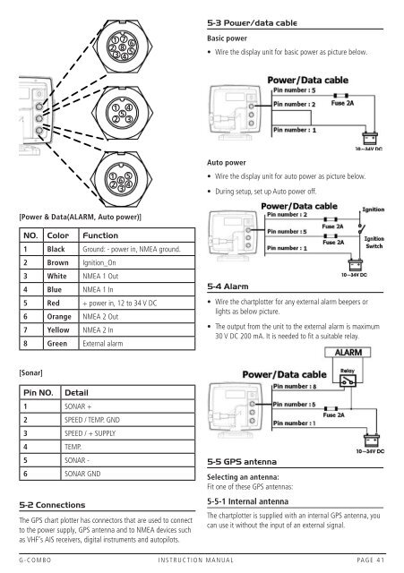
5-3 Power/data cableBasic power• Wire the display unit for basic power as picture below.Auto power• Wire the display unit for auto power as picture below.• During setup, set up Auto power off.[Power & Data(ALARM, Auto power)]NO. Color Function1 Black Ground: - power in, NMEA ground.2 Brown Ignition_On3 White NMEA 1 Out4 Blue NMEA 1 In5 Red + power in, 12 to 34 V DC6 Orange NMEA 2 Out7 Yellow NMEA 2 In8 Green External alarm5-4 Alarm• Wire the chartplotter for any external alarm beepers orlights as below picture.• The output from the unit to the external alarm is maximum30 V DC 200 mA. It is needed to fit a suitable relay.[Sonar]Pin NO.Detail1 SONAR +2 SPEED / TEMP. GND3 SPEED / + SUPPLY4 TEMP.5 SONAR -6 SONAR GND5-2 ConnectionsThe GPS chart plotter has connectors that are used to connectto the power supply, GPS antenna and to NMEA devices suchas VHF’s AIS receivers, digital instruments and autopilots.5-5 GPS antennaSelecting an antenna:Fit one of these GPS antennas:5-5-1 Internal antennaThe chartplotter is supplied with an internal GPS antenna, youcan use it without the input of an external signal.G-COMBO INSTRUCTION MANUAL PAGE 41