Lab 6: Double Einstein Ring System SDSSJ0946+1006 - UGAstro
Lab 6: Double Einstein Ring System SDSSJ0946+1006 - UGAstro
Lab 6: Double Einstein Ring System SDSSJ0946+1006 - UGAstro

You also want an ePaper? Increase the reach of your titles
YUMPU automatically turns print PDFs into web optimized ePapers that Google loves.
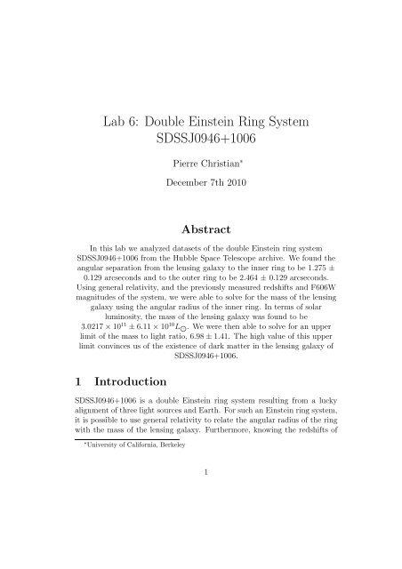
<strong>Lab</strong> 6: <strong>Double</strong> <strong>Einstein</strong> <strong>Ring</strong> <strong>System</strong><strong>SDSSJ0946+1006</strong>Pierre Christian ∗December 7th 2010AbstractIn this lab we analyzed datasets of the double <strong>Einstein</strong> ring system<strong>SDSSJ0946+1006</strong> from the Hubble Space Telescope archive. We found theangular separation from the lensing galaxy to the inner ring to be 1.275 ±0.129 arcseconds and to the outer ring to be 2.464 ± 0.129 arcseconds.Using general relativity, and the previously measured redshifts and F606Wmagnitudes of the system, we were able to solve for the mass of the lensinggalaxy using the angular radius of the inner ring. In terms of solarluminosity, the mass of the lensing galaxy was found to be3.0217 × 10 11 ± 6.11 × 10 10 L J . We were then able to solve for an upperlimit of the mass to light ratio, 6.98 ± 1.41. The high value of this upperlimit convinces us of the existence of dark matter in the lensing galaxy of<strong>SDSSJ0946+1006</strong>.1 Introduction<strong>SDSSJ0946+1006</strong> is a double <strong>Einstein</strong> ring system resulting from a luckyalignment of three light sources and Earth. For such an <strong>Einstein</strong> ring system,it is possible to use general relativity to relate the angular radius of the ringwith the mass of the lensing galaxy. Furthermore, knowing the redshifts of∗ University of California, Berkeley1
the lensing galaxy and the annulus would allow us to solve said relation forthe mass of the lensing galaxy completely in terms of the angular radius ofthe ring. This method of mass determination, coupled with photometry ofthe lensing galaxy, would allow us to calculate the mass to light ratio of saidgalaxy, thereby helping us understand the dark matter distributions of thegalaxy.For this lab, we would require Hubble Space Telescope images of <strong>SDSSJ0946+1006</strong>taken free from atmospheric disruption, thereby possessing high enough resolutionfor us to resolve the lensing galaxy of the system along with its two<strong>Einstein</strong> rings. We would then analyze the image to find the angular radiusof the first <strong>Einstein</strong> ring in order to measure the mass content of the lensinggalaxy.2 Theoretical Considerations2.1 Gravitational LensingWhen light travels close to a massive object, general relativity dictates thatlight bends inwards towards the mass following the curvature in spacetimeintroduced by said mass. If an observer is to be located behind the mass(which is located behind the light source), and is positioned exactly at thestraight line intersecting both the mass and the light source, the observerwould see an annulus around the mass due to this bending of light. Thisphenomenon created what is known as an <strong>Einstein</strong> ring system. In such<strong>Einstein</strong> ring systems, the angular separation between the lensing mass andthe annulus, denoted as θ, can be calculated by the equation 1 :θ =√α 0R 0d L(1)Where α 0 is the angular bending of the light path as it crosses the gravitatingmass, R 0 is the radius of the gravitating object (assumed to be circular),and d L is the distance between the observer and the massive object.In such systems, however, we can solve for α 0 , resulting in θ as a functionof the mass of the massive object (called the lensing object) and the three1 <strong>Einstein</strong>, 1936: Lens-Like Action of a Star by the Deviation of Light in the GravitationalField (Science Vol. 84, No. 2188, pg 506-507)2
distances between the lensing object, the observer, and the annulus by theequation 2 :θ E1 =√4GM(d S1 − d Lc 2 (d S1 d L )(2)Where now d S1 is the distance between the observer and the resultingannulus, d L is the distance between the observer and the lensing object,and M is the mass of the lensing object. In the last equation, the angulardistance between the lensing mass and the <strong>Einstein</strong> ring is denoted as θ E1where the subscript is used as an index shall we have multiple <strong>Einstein</strong> ringsin the system. It is notable, however, that due to the small value of thegravitational constant, G, in the numerator, and the large value of the speedof light, c, in the denominator, we need a lensing object of immense mass toachieve an annulus located at a distance appreciable enough from the lensingmass that it is detectable at all using our equipments. A further complicationin observing this phenomenon is the scarcity of a light source and a lensingmass that is perfectly aligned with our observers on Earth.Miraculously, our dataset depicts a double <strong>Einstein</strong> ring system achievedusing a galaxy as its final lensing object. The light from the first light sourcewas bended by the second object, which also produced light which is bendedby the final lensing galaxy. In addition, the bended light of the first lightsource is further bended by the final lensing galaxy. As these three objectsare perfectly aligned with Earth, we can see the bending of the lights astwo luminous rings encircling the final lensing galaxy, with the light fromthe closer lensed source forming the inner ring and light from the first lightsource as the outer ring.2.2 Mass Determination of Lensing ObjectsIf an <strong>Einstein</strong> ring system is bright enough, spectroscopy can be used to findthe cosmological redshift, z, of the annulus and the lensing object. For lowredshifts (z < 2), the conversion between cosmological redshift and distanceto Earth, d, for known Hubble constant at the current epoch, H 0 , is givenby 3 :2 Kalas, 2010: <strong>Lab</strong> 6 - Gravitational Lensing, pg 123 Kalas, 2010: <strong>Lab</strong> 6 - Gravitational Lensing, pg 123
d ∼( ) ( )c (z + 1) 2 − 1H 0 (z + 1) 2 + 1(3)As such, for bright <strong>Einstein</strong> ring systems, both the distances between theobserver and the lensing object, and between the observer and the annulus,can be measured. If additionally the angular separation between the lensingobject and the annulus is measured, we can use the two distances andEquation (2) to solve for the mass of the lensing galaxy.3 Equipment and Observation3.1 Hubble Space TelescopeThe Hubble Space Telescope (HST) utilizes a 2.4 meter primary mirror orbitingat 559 km from the ground to take images free from atmosphericdistortion. Our dataset made use of the now retired Wide Field and PlanetaryCamera 2 (WFPC2), consisting of three Wide Field Cameras (WF1,WF2, and WF3) and one higher resolution, but correspondingly smaller fieldof view Planetary Camera (PC). All four cameras contained an 800x800 pixelsCCD detector. The three Wide Field Cameras possess a plate scale of 0.1arcsec/pixel, while the Planetary Camera possess a finer plate scale of 0.046arcsec/pixel.3.2 ObservationOur dataset were obtained from the online Hubble archieve 4 . We selectedfour datasets of <strong>SDSSJ0946+1006</strong> taken using HST’s WFPC2 camera utilizingthe F606W filter. These datasets have HST proposal ID 11202 andPI Leon Koopmans of the Kapteyn Astronomical Institute. For all datasets,we chosed to download the pipeline calibrated version, meaning that ourimages were already corrected for flat fields, geometric distortions (such asvigneting), dark counts, and bias.Our field consisted of observations from four cameras of the WFPC2.The three Wide Field Cameras are arranged to have an ’L’ shaped field ofview, measuring 160 arcseconds across its two long edges. Nestled at the4 at http://archive.stsci.edu/hst/4
top right corner of this field is the smaller field of view of the PlanetaryCamera, a box measuring 36.8 arcseconds across. Our target, the <strong>Einstein</strong><strong>Ring</strong> <strong>System</strong> <strong>SDSSJ0946+1006</strong>, was captured within the field of WF3 locatedat the bottom left corner of the entire WFPC2 field of view.The observation, conducted on December 17 2007 at 21:06:17 UT, utilizesthe F606W filter which spans 1502 angstroms about 5997 angstroms. Theintegration time used was 1100 seconds.3.3 Cosmic Rays and Sky BackgroundIn order to reject cosmic rays, we coadded our four images together by takingthe median of each pixels of the four images. Since it is improbablefor cosmic rays to hit the same pixels on more than one of our images, bytaking the median we could effectively remove them. In practice, before wecoadd them in this manner, we have to first align the four images. This isbecause HST’s revolution around the Earth caused an apparent movement ofthe <strong>Einstein</strong> ring system between each exposures. Despite HST’s automatictracking system, the pixel location of our target differs considerably betweenthe images.In order to align the images, we first determine the centroid pixel positionsof the lensing galaxy of all four images using the IRAF command imcntr. Thevalues are presented in Table 1. Also presented in the table are the differencesbetween the galaxy’s centroid of a particular image and the galaxy’s centroidin the first image. Shifting the second, third, and fourth images by thesedifferences would effectively align them with the first image. In practice,these alignments are done using IRAF’s imshift command.Image Number x Pos (Pix) y Pos (Pix) x-difference (Pix) y-difference (Pix)1 366.475 376.860 0 02 371.486 379.296 -5.01 -2.433 374.011 384.322 -7.54 -7.464 369.008 381.885 -2.53 -5.03Table 1: Pixel centroid position of the lensing galaxy in the four images.The x-difference and y-difference columns corresponds to the differences ofthe centroid positions between the image and the first image.5
The median coaddition of the first image and the shifted second, third,and fourth images was then done using IRAF’s imcombine utilizing thecomb=median keyword. The mean, median, mode, and standard deviationof a small empty region (at [125:174, 135:184] can be obtained for our imagesusing IRAF’s imstat package (utilizing the field keyword). The statistics forfour of our original images, along with their average value, are listed in Table2. The same statistics, this time calculated for the combined image, arelisted in Table 3. Note that the standard deviation of the combined image islower by a factor of ∼ 9.5 from the average of the four single images. Thiscorresponds to the coaddition reducing the sky background noise.Image Number Mean (ADU) Median (ADU) Mode (ADU) Stddev (ADU)1 0.02035 0.01934 0.0193 0.0122mmmm2 0.02216 0.02178 0.02169 0.00403 0.01962 0.01927 0.01949 0.00404 0.02273 0.02176 0.02164 0.0072Average 0.02122 0.02054 0.02053 0.00685Table 2: Image statistics for the four exposures, taken at a small, emptyregion at position [125:174, 135:184].Image Mean (ADU) Median (ADU) Mode (ADU) Stddev (ADU)Combined 0.0206 0.02053 0.02027 7.2 × 10 −4Table 3: Image statistics of the median coadded image, taken at a small,empty region at position [125:174, 135:184]. Note that the standard deviationdrops by ∼ 9.5 from the average of the single images.Also notable from Table 3 is that although the HST is located above theatmosphere, therefore exempt to sky background due to light reflecting offthe atmosphere, the median of the empty region is not zero. This means thatour HST data is still polluted by some sky background. Some cause of thislight pollution is the reflection of sunlight by dust in the zodiacal cloud: athin, flat, dust cloud located within the solar system. Nevertheless, we would6
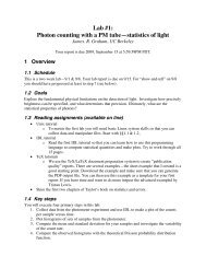
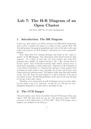
need to remove this sky background by subtracting our coadded image by themedian data number of an empty patch of sky. This was achieved by usingIRAF’s imarith to subtract the median listed in Table 3 from our coaddedimage. The resulting image is shown in Figure 1 (a). Shown in Figure 1 (b)is the magnified field of view of WF3.4 Resulting ImageIn Figure 1 (b), E denotes a bright star that we used to get our experimentalpoint spread function. The FWHM of the star, measured using IRAF’sradprof package, denotes the angular resolution of the image in the bandpass.The pixel FWHM obtained for this star is 2.64 pixels. Converting this intoarcseconds using the plate scale (0.1 arcseconds per pixel), we get the angularresolution of the image to be 0.264 arcseconds. The theoretical best angularresolution for a telescope is given by ∼ λ where λ denotes the wavelengthDobserved and D denotes the diameter of the telescope. Plugging in the centerwavelength of our bandpass, 599.7 nm, and the diameter of the HST, 2.4 m,we get a theoretical best angular resolution of 0.0515 arcseconds. Therefore,our achieved angular resolution is 5.122 times larger than the theoretical best.This meant that although the HST is free from atmospheric disturbances,it still fail to attain the best possible angular resolution. This can be dueto the diffraction of its apperture which worsen its angular resolution by ageometric factor, or imperfections in the mirror itself.Besides the <strong>Einstein</strong> ring system, the field of Figure 1 (b) is also litteredwith various other interesting objects. A, B, C, and D, for example, are othergalaxies. If spectras are taken for each of those galaxies, we would be able tomeasure their cosmological redshifts. By equation (2), we would then be ableto find their distances from Earth. With this information, it is possible tofigure out if all five galaxies are located close to each other in 3-D space, or ifonly their 2-D projections are near each other (since our image only showedtheir 2-D projection). We can then discern how many of those galaxies aregravitationally affecting each other. If we can measure their velocity vectors,we would then be able to discern if any of them form gravitationally boundsystems. Another interesting note is that galaxy A possess extended featuresthat looks disturbed. This hints that galactic interactions (such as galacticcollisions) happened to galaxy A in the past. It would be interesting toobserve galaxy A through a different bandpass. If it is the subject of a7
(a)(b)Figure 1: (a) Shows the entire field of our WFPC2 <strong>SDSSJ0946+1006</strong> datasetafter cosmic ray and sky background rejection. The three large boxes arrangedlike an ’L’ are the Three WFC camera field of views. Each of the boxmeasure 80 arcseconds across. The smaller 8 box at top right corner is the PCfield of view measuring 36.8 arcseconds across. (b) Shows the magnified fieldof view of WF3, where our target <strong>Einstein</strong> ring system resides. The letterlabels A-E denotes other interesting objects in the field.
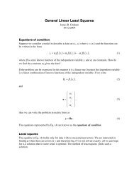
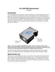
galactic collision, for example, perhaps we can see a trail of hot gaseousmatters which leads to the direction the other galaxy went after the collisionif we look at the field through a different wavelength range. Due to therarity of lensing events, it would be improbable to find another <strong>Einstein</strong> ringsystem in the field. Looking through the other objects closely confirmedthis. None of the other objects displayed any morphology that bends orcurves the way an <strong>Einstein</strong> annulus does. In the most cases, objects in thefield possessed morphology that are circular or elliptical. Some of the smallerdots are actually cosmic rays that survived our cosmic ray rejection method.This was ascertained by blinking through the four single images in ds9. Manyof the smaller dot features appear in two consequetive images but not in therest, a tell tale sign of cosmic rays.The contour plot of the field surrounding our target <strong>Einstein</strong> ring systemis shown in Figure 2 (a). The same plot zoomed into our target <strong>Einstein</strong>ring system is shown in Figure 2 (b). Notice the large elliptical structurein Figure 2 (a). This structure, which is not apparent without the contourlines, are the galaxy isophotes of the fainter, extended region of the galaxy.In Figure 2 (b), an interesting note is that the isophote of the central portionsof the lensing galaxy rotates as the radius increases. Therefore, it is as if thelensing galaxy is made of two parts, a central, smaller but brighter part, andan extended, large but faint part. Using IRAF’s imcntr, we calculated thecentroid position of the lensing galaxy to be [366.475, 376.860]. Furthermore,using the IRAF package radprof, we were able to calculate the FWHM ofthe galactic center to be of 4.98 pixels, or 0.498 arcseconds. Using the samemethod, the semimajor axis of the extended part of the galaxy is measured tobe 52.5 pixels, while the semiminor axis is 36 pixels. Multiplying by the platescale, these numbers corresponds to 5.25 and 3.6 arcseconds respectively.5 Galaxy SubtractionFor the purpose of emphasizing the lenses’ structures, we can remove thelensing galaxy from our coadded image. This removal can be done by firstmodelling the galaxy and then subtracting this model galaxy from our coaddedimage.9
(a)(b)Figure 2: (a) Shows the contour plot of the field surrounding<strong>SDSSJ0946+1006</strong> after cosmic ray and 10 sky background rejection. Note thelarge elliptical structure that extends further from the directly apparent regionof the galaxy. This fainter portion of the galaxy is due to the galaxy’sextended regions. (b) Shows the same contour plot as (a) magnified to emphasizethe central parts of <strong>SDSSJ0946+1006</strong>. Note the isophote’s twisting(rotating) as it increases radius.
5.1 de Vaucouleurs’ Model GalaxyA simple elliptical galaxy model that we used in modelling the lensing galaxywas the de Vaucouleurs’ model. The de Vaucouleur profile describes thesurface brightness, I, of an elliptical galaxy as a function of the galacticradius, R, as 5 :lnI(R) = lnI 0 − kR 1/4 (4)Where I 0 is the surface brightness at the center of the galaxy and k is aproportionality constant. Defining R e as the radius where half the luminosityof the galaxy is contained, we can eliminate the proportionality constant kto write the de Vaucouleur profile as:lnI(R) = lnI e + 7.67(1 −( ) )1R4R e(5)As such, a de Vaucouleur elliptical galaxy can be completely specified byits magnitude, semimajor axis, and axial ratio (semimajor divided by semiminoraxis), as well as its position coordinates and position angle describing thegalaxy’s location and rotation placement in the field.5.2 Galaxy Modelling and Subtraction MethodOur de Vaucouleur galaxy can be modelled using IRAF’s mkobject package.This package allowed the creation of images based on various theoreticalmodels. In this case, we used mkobject to construct a de Vaucouleur galaxyby feeding it a text file containing the centroid position, the magnitude,the name of the galaxy model, the semimajor axis, the axial ratio, and theposition angle of the model galaxy. To model our galaxy, due to the profileof the galaxy isophotes described in section 4, we have to superimpose twode Vaucouleur galaxies. The first component would be a brighter galaxy thatwould model the central parts of our lensing galaxy. The second componentwould be a fainter galaxy to model the extended portions of our lensinggalaxy. The parameters which goes into building these two galaxies aregiven in Table 4. The centroid positions of both galaxy components are thecentroid position of our lensing galaxy [366.475, 376.860].11
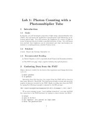
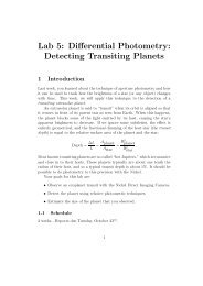
Magnitude Semimajor Axis (Pix) Axial Ratio Position Angle (degrees)2 20 0.95 55 20.2 0.9 80Table 4: Parameters of the two de Vaucouleur galaxies used to model ourlensing galaxy. The first entry described a brighter galaxy that models thecentral portions of our lensing galaxy while the second entry described afainter one that models the extended features of our lensing galaxy.Our model galaxy can then be subtracted from the coadded image usingIRAF’s imarith’s image subtraction. The resulting image of our target <strong>Einstein</strong>ring system, is shown in Figure 3 (a) while the contour plot is shownin Figure 3 (b). Note that in Figure 3 (b), the large elliptical contours ofthe galaxy’s extended portion is absent. Thus, this model works very wellin the extended part of our lensing galaxy. The black patch at the centralregions of the galaxy, however, indicates that our model had oversubtract onsome center parts of the lensing galaxy. This is because the central portionsof the lensing galaxy was not completely elliptical, while our model for thecenter of the galaxy is a perfectly elliptical object. As the ellipse of our modelgalaxy thus covers more than the entire galactic center, some parts of thegalaxy center was oversubtracted by our model galaxy. Also note that incontrast with Figure 2 (b), the upper portion of the inner <strong>Einstein</strong> ring isvery apparent.6 High Pass FilteringPutting an image through a high pass filter would remove low resolutionstructures. In effect, broad objects such as the extended morphology of thelensing galaxy would be deemphasized while smaller details such as stars orthe core of a galaxy would be accentuated. By passing our image througha high pass filter, we therefore can increase the apparent sharpness of theimage without actually obtaining new data.In this lab, the high pass filter was made by convolving our coadded imagewith a gaussian function using the IRAF package gauss. This convolutionresults in a copy of our image that is deliberately blurred, where the extend5 Caroll & Ostlie, 1996: Modern Astrophysics, pg. 92812
(a)(b)Figure 3: (a) Shows <strong>SDSSJ0946+1006</strong> after we subtracted our model galaxy.Note that the center galaxy is oversubtracted. 13 This is due to the centerof the galaxy not being a perfect ellipse, while our model for the center ofthe galaxy is a perfectly elliptical object. (b) Shows the contour plot of thegalaxy. Note that in contrast to the contour plot before the model galaxysubtraction, the large elliptical isophotes due to the extended portions of thegalaxy is missing. This shows that our model is a good fit for the extendedregions of the galaxy.
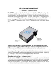
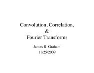
of the blurring depends on the standard deviation of the gaussian (increasingthe standard deviation of the gaussian would blur the image more). We thenused IRAF’s imarith to subtract our coadded image with its convolved copy.As the convolved image is essentially a low pass filter, the subtraction wouldcancel the low resolution structures (which are practically unaffected by theconvolution) almost completely while leaving the high detailed structuresintact. The choice of gaussian σ reflects how sharp the resulting high passfiltered image would be. A larger σ would increase the frequency thresholdthat would not pass the filter. As such, choosing a higher σ would amountto increasing the apparent sharpness of the resulting high pass image. Wechose σ = 5 as a compensation between sharpening the image enough toremove the extended morphology of the galaxy, while still passing as muchinformation as possible (since at very high frequency filters, even the ringswould be filtered, changing their shapes significantly). Our target <strong>Einstein</strong>ring system after applying high pass filtering of gaussian σ = 5 is depictedin Figure 4. As seen, the extended structures of the galaxy are removedand the smaller details (such as the lensing galaxy center and the rings) areemphasized. In contrast with Figure 2 (b), for example, the upper portionof the inner <strong>Einstein</strong> ring is clearly visible.7 AstrometryThe radial angular separation between the lens galaxy and the rings weredone by plotting a cut of the image using IRAF’s graph package. A verticalradial cut was made across the <strong>Einstein</strong> ring system at pixel 368 horizontallyand between pixel 343 to 405 in the vertical direction of the high pass filteredimage (the dotted line in Figure 4).The resulting radial cut, plotting pixel in the vertical direction versus thedata number is shown in Figure 5. In the figure, the large peak with centroidat pixel 35.2 ± 1.29 corresponds to the center of the lensing galaxy, where theuncertainty due to the centroid method is obtained by taking 200 centroidcalculations with different starting position (determined in IDL using thecursor function) and taking the standard deviation of the results. The twosmaller dips with centroid positions at 21 pixel and at 46.5 corresponds tothe light emissions of the inner ring, while the even less pronounced dipat pixel 58.5 is due to the outer ring. Since they were all calculated withthe same centroid function, they all carry the same uncertainty of ± 1.2914
Figure 4: <strong>SDSSJ0946+1006</strong> after high pass filtering. We convolved our coaddedimage with a gaussian of sigma=5 and subtract this convolution from theoriginal image, creating a high-passed image. Note that the central portionof the galaxy and the rings are accentuated. The dotted lines correspondsto the cut done to produce a pixel vs. data number plot in the Astrometrysection.15
pixels. The absolute pixel differences between the centroids of the inner ringemissions and the central galaxy emission are therefore 14.2 ± 1.29 pixels(to the upper ring) and 11.3 ± 1.29 pixels (to the lower ring). Averagingthese two pixel regress gives the mean pixel annulus of the inner ring to be12.75 ± 1.29 pixels. Multiplying this number by the plate scale of WF3, 0.1arcsec/pixel, we get the angular separation of the inner annulus to be 1.275± 0.129 arcseconds. We can confidently detect only one side of the outer ringemission, due to it being fainter. The pixel difference between the centroid ofthe central galaxy and the centroid of the outer ring emission is 23.3 ± 1.29pixels. Again, multiplying this number by the plate scale of WF3 gives usthe angular separation of the outer annulus to be 2.33 ± 0.129 arcseconds.If we are to use, instead of the high pass filter, the model galaxy subtractedimage from the previous section, we would gain another method bywhich we can calculate the rings’ radial angular separation. Taking a radialcut of the image at the same location, we would obtain the same centroidpositions for the rings’ emissions. However, we would need a new methodto find the center of our lensing galaxy. Since our model galaxy succeededin canceling out the actual galaxy, then the location of the galaxy’s centershould be located at the position we placed the center of the model galaxy[366.475, 376.860]. The vertical position of our galaxy is therefore 376.860.This corresponds to pixel number 33.86 in Figure 5 (the image in Figure 5starts at pixel 343, therefore, the pixel position of the model galaxy in Figure5 is pixel number 376.860 − 343 = 33.86). The absolute pixel differencesbetween this new centroid and the two inner ring emission lines visible inFigure 5 are 12.86 (for the distance to the upper ring) and 12.64 (for thedistance to the lower ring). Since the rings’ emission centroids still carrythe centroid uncertainty, these values have uncertainty of ± 1.29 pixels. Theaverage of these values again give us the average pixel angular separation ofthe inner annulus to be 12.75 ± 1.29 pixels, or multiplying by the plate scale,1.275 ± 0.129 arcseconds. Doing the same procedure with the single outerring centroid give the angular separation of the outer ring to be 24.64 ± 1.29pixels, or multiplying by the plate scale, 2.464 ± 0.129 arcseconds. The factthat we get similar answers using both methods means that for the purposesof this lab, it does not really matter which method were used in subtractingthe lensing galaxy.16
Figure 5: Plot of pixel in the vertical direction versus data number of<strong>SDSSJ0946+1006</strong>. This image was made by making a vertical cut acrossthe <strong>Einstein</strong> ring system at [368, 343:405] (depicted as the dotted line acrossFigure 4) of the high pass filtered image. Note the large peak at 35.2 pixeldue to the center of the lens galaxy, the two smaller peaks at 21 and 46.5 dueto the inner ring, and the even smaller peak at 58.5 due to the outer ring.17
8 Dark Matter AnalysisThe redshifts to the lensing galaxy and the inner ring are known to be 0.222and 0.609 respectively (the outer ring is too faint for redshift measurements).By the methods of section 2.2, we could use this information, along with theangular separation of the first ring obtained in the previous section, to solvefor the mass of the lensing galaxy. Using equation (3), and the WMAP valueof H 0 (71 (km/sec)/Mpc), we calculated the distance between Earth and thelensing galaxy to be 835.97 Mpc and the distance between Earth and theinner ring to be 1870.66 Mpc.The mass of the galaxy can be solved from equation (2) to be:M = θ2 E1 c2 (d S1 d L )4G(d S1 − d L )(6)The uncertainty of the measurement can be found using the error propagationequation 6 : for an observable I(F 1 , F 2 , ..., F N ), the error, δI is givenby:√ ( ) 2 ( ) 2 ∂I∂IδI = δF 1 + ... + δF N (7)∂F 1 ∂F NWhere in this case the equation reduces to:δM =√ ( ∂M∂θ E1δθ E1) 2(8)Where δθ E1 is the uncertainty in the angular separation between the firstring and the center of the lensing galaxy. From equation (6):∂M= 2θ E1c 2 (d S1 d L )∂θ E1 4G(d S1 − d L )(9)And therefore the error propagation equation reads:6 Taylor: An Introduction to Error Analysis18
δM =2θ E1 c 2 (d S1 d L )∣ 4G(d S1 − d L ) ∣ δθ E1 (10)Equation (6) and (10) gives the mass of the lensing galaxy to be 3.0217 ×10 11 ± 6.11 × 10 10 M J .There are two ways to measure the luminosity of the lensing galaxy. Thefirst is to assume that the entirety of our galactic mass is in the form ofSun-like stars. As such, the total luminosity of the galaxy, L g would be givenby:L g = M gM J × LJ (11)Where M J and L J are the mass and luminosity of the sun, respectively,and M g is the mass of the galaxy. In this case the error propagation equation(7) reduces to:δL g = LJM J × δM g (12)Equation (11), used along with the error propagation equation (7), givesthe luminosity of the galaxy if the entirety of its mass is in the form ofSun-like stars to be 3.0217 × 10 11 ± 6.11 × 10 10 L J .This assumption is innacurate because the lensing galaxy is an ellipticalgalaxy, which typically consists of mostly old red stars, while the star isof a relatively younger yellow G-dwarf star population. Furthermore, thisassumption neglects the fact that the galaxy’s luminosity in this bandpasscan also come in the form of non-stellar masses, such as hot interstellar gases.The most interesting error of this calculation, however, is that it does nottake into account dark matter, which contributes to the mass but not to theluminosity of the galaxy.The second way to measure the luminosity of the lensing galaxy wouldbe to perform photometry on the lensing galaxy. Due to time constraints,we were not able to conduct the photometry ourselves. Fortunately, theapparent magnitude, m g , of the lensing galaxy is known to be 17.78 mag in19
our bandpass (F606W). Using the distance modulus, we can calculate theabsolute magnitude, M g of the galaxy by 7 :( ) dM g = m g − 5log 1010pc(13)Where d, the distance to the lensing galaxy, was obtained using the measuredredshift to the galaxy and equation (3) to be 835.97 Mpc. This equationgives the absolute magnitude of the lensing galaxy in the F606W bandpassto be -21.830 mag. We can then calculate the luminosity of the galaxy in thebandpass, L g , in terms of the Sun’s luminosity, L J , using the equation:M g = M J − 2.5log 10(LgL J )(14)Where the absolute magnitude of the sun, M J , is known to be 4.76 mag.Solving for L g in this equation gives:L g = L J × 10 MJ −Mg2.5 (15)This gives the luminosity of the lensing galaxy in the bandpass to be4.329 × 10 10 L J . Note that this result is much smaller than if we assumethat the mass of the galaxy consists of entirely Sun-like stars (By a factorof 6.98). This is due to two factors: the first is that our first luminositycalculations does not take into account the fact that a large portion of thegalactic mass does not radiate in the same way as the sun (because some ofthe luminous matter might be non-stellar objects, such as hot gas, and mostof the stellar objects in the elliptical galaxy would be old, red stars). Thesecond factor is because most of the mass of the elliptical galaxy is in theform of non-luminous dark matter.The mass to light ratio of the lensing galaxy, defined as its mass in solarmass divided by its luminosity, can be calculated using the luminosity foundusing the second method to be 6.98±1.41 where the uncertainty follows fromequation (7). The mass to light ratio gives a picture of the amount of massthat does not radiate photons (at least within the bandpass). As such, it is7 Caroll & Ostlie, 1996: Modern Astrophysics, pg. 6820
a measure of how much dark matter is in the galaxy. Since our mass to lightratio is > 1, we can confidently say that we detected the presence of darkmatter in the lensing galaxy. However, we have assumed that all luminousobjects radiates exclusively within the F606W bandpass as our luminosityis calculated using the magnitude of the lensing galaxy within the F606Wbandpass only. Therefore, any objects that radiates outside the bandpasswould increase our mass to light ratio despite not being dark matter. In particular,we have overcounted the amount of dark matter by adding luminousmatter that radiates outside our bandpass. This means that our mass tolight ratio is merely an upper limit, if there exist any material in the galaxythat radiates outside our bandpass, the mass to light ratio would lower. Forexample, since stars radiate in a manner very similar to blackbody radiation,it would radiate a finite amount of energy at every wavelength. Therefore,some of their luminosity must be radiated outside of the F606W bandpass.9 ConclusionUsing the Hubble Space Telescope data achieve, we were able to obtaindatasets of the double <strong>Einstein</strong> ring system <strong>SDSSJ0946+1006</strong> and solve forthe angular separation of the inner ring and the lens galaxy. By the tenets ofgeneral relativity, we were able to use this information, along with the knownredshifts and magnitudes of the system to find an upper limit of the massto light ratio, 6.98 ± 1.41. The high value of this mass to light ratio allowedus to be confident in stating that we have found dark matter in the lensinggalaxy of <strong>SDSSJ0946+1006</strong>. A concern of this lab is the large uncertainty weobtained (20% for the mass to light ratio). Most of this uncertainty comesfrom the uncertainty of the angular separation due to the centroid function.Therefore, in analyzing future datasets, it would be beneficial to use a bettermethod to find the center of an emission line (such as gaussian or polynomialfitting). Nevertheless, this lab allowed us to observe firsthand the curvatureof spacetime due to massive objects, as well as using this curvature to confirmthe existence of the exotic dark matter.21
10 Appendix: <strong>Double</strong> <strong>Einstein</strong> <strong>Ring</strong> Geometry22