P0335, P0339 Crankshaft Position Sensor 'A ... - Highlander Club
P0335, P0339 Crankshaft Position Sensor 'A ... - Highlander Club
P0335, P0339 Crankshaft Position Sensor 'A ... - Highlander Club

Create successful ePaper yourself
Turn your PDF publications into a flip-book with our unique Google optimized e-Paper software.
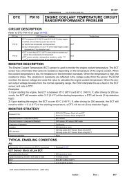
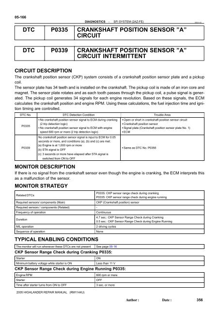
05-166DIAGNOSTICS-SFI SYSTEM (2AZ-FE)05ESY-05DTC <strong>P0335</strong> CRANKSHAFT POSITION SENSOR ”A”CIRCUITDTC <strong>P0339</strong> CRANKSHAFT POSITION SENSOR ”A”CIRCUIT INTERMITTENTCIRCUIT DESCRIPTIONThe crankshaft position sensor (CKP) system consists of a crankshaft position sensor plate and a pickupcoil.The sensor plate has 34 teeth and is installed on the crankshaft. The pickup coil is made of an iron core andmagnet. The sensor plate rotates and as each tooth passes through the pickup coil, a pulse signal is generated.The pickup coil generates 34 signals for each engine revolution. Based on these signals, the ECMcalculates the crankshaft position and engine RPM. Using these calculations, the fuel injection time and ignitiontiming are controlled.DTC No. DTC Detection Condition Trouble Area<strong>P0335</strong><strong>P0339</strong> No crankshaft position sensor signal to ECM during cranking(2 trip detection logic) No crankshaft position sensor signal to ECM with enginespeed 600 rpm or more (2 trip detection logic)No crankshaft position sensor signal is input to ECM for 0.05seconds or more, and conditions (a), (b) and (c) are met:(a) Engine is at 1,000 rpm or more(b) STA signal is OFF(c) 3 seconds or more have elapsed after STA signal isswitched from ON to OFF Open or short in crankshaft position sensor circuit <strong>Crankshaft</strong> position sensor Signal plate (<strong>Crankshaft</strong> position sensor plate No. 1) ECM Same as DTC No. P0355MONITOR DESCRIPTIONIf there is no signal from the crankshaft sensor even though the engine is cranking, the ECM interprets thisas a malfunction of the sensor.MONITOR STRATEGYRelated DTCs<strong>P0335</strong>: CKP sensor range check during cranking<strong>P0335</strong>: CKP sensor range check during engine runningRequired sensors/ components (Main)CKP (<strong>Crankshaft</strong> position) sensorRequired sensors / components (Related) -Frequency of operationContinuousDuration4.7 sec.: CKP <strong>Sensor</strong> Range Check during Cranking0.5 sec.: CKP <strong>Sensor</strong> Range Check during Engine RunningMIL operation2 driving cyclesSequence of operationNoneTYPICAL ENABLING CONDITIONSThe monitor will run whenever these DTCs are not present See page 05-16CKP <strong>Sensor</strong> Range Check during Cranking <strong>P0335</strong>:StarterMinimum battery voltage while starter is ONONLess than 11 VCKP <strong>Sensor</strong> Range Check during Engine Running <strong>P0335</strong>:Engine RPMStarterTime after starter turns from ON to OFF600 rpm or moreOFF3 sec. or more2005 HIGHLANDER REPAIR MANUAL (RM1144U)Author:Date:356
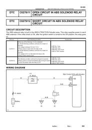
DIAGNOSTICSTYPICAL MALFUNCTION THRESHOLDSCKP signalCOMPONENT OPERATING RANGECKP signalWIRING DIAGRAMNo signal-SFI SYSTEM (2AZ-FE)05-167CKP sensor voltage fluctuates when the crankshaft rotates 34 CKP signals per 1revolution crankshaftC1Camshaft <strong>Position</strong> <strong>Sensor</strong>1ShieldedY27E9G2+ECMSignal Rotor onIntake Camshaft2L1ShieldedR25E9NE+<strong>Crankshaft</strong> Angle<strong>Sensor</strong> PlateC7<strong>Crankshaft</strong> <strong>Position</strong> <strong>Sensor</strong>2GAAAGJ7J/CA BRBR24E91E9NE-E1EEINSPECTION PROCEDUREHINT: Read values on the hand-held tester or OBD II scan tool.(a) Connect the hand-held tester or the OBD II scan tool to the DLC3.(b) Start the engine and push the hand-held tester or the OBD II scan tool main switch ON.(c) Enter the following menus: DIAGNOSIS / ENHANCED OBD II / DATA LIST / ALL / ENGINE SPD. The engine speed can be confirmed in DATA LIST using the hand-held tester or OBD II scan tool. Ifthere are no NE signals from the crankshaft position sensor despite the engine revolving, the enginespeed will be indicated as zero. If voltage output of the crankshaft position sensor is insufficient, theengine speed will be indicated as lower than the actual rpm. Read freeze frame data using the hand−held tester or the OBD II scan tool. Freeze frame data recordsthe engine conditions when a malfunction is detected. When troubleshooting, freeze frame data canhelp determine if the vehicle was running or stopped, if the engine was warmed up or not, if the air-fuelratio was lean or rich, and other data from the time the malfunction occurred.A902992005 HIGHLANDER REPAIR MANUAL (RM1144U)Author:Date:357
05-168DIAGNOSTICS-SFI SYSTEM (2AZ-FE)1 INSPECT CRANKSHAFT POSITION SENSOR (RESISTANCE)A64984(a)(b)Disconnect the C7 sensor connector.Measure the resistance between the terminals of the sensor.Standard:Tester Connection Condition Specified Condition1 - 2 Cold 985 to 1,600 Ω1 - 2 Hot 1,265 to 1,890 ΩNOTICE:In the above section, the terms ”cold” and ”hot” refer to thetemperature of the coils. ”Cold” means approximately-10 C to 50C (14F to 122F). ”Hot” means approximately50C to 100C (122F to 212F).E9ECMHINT:Reference: Inspection using an oscilloscope.During cranking or idling, check the waveform between the terminalsof the ECM connector.Standard:Tester ConnectionSpecified ConditionE9-27 (G2+) - E9-24 (NE-)E9-25 (NE+) - E9-24 (NE-)Correct waveform is as shownG2+NE+NE-G2+ and NE+ Signal Waveforms2 V/DivisionG2+NE+A81699A7690320 msec./Division (Idling)A87927NGREPLACE CRANKSHAFT POSITION SENSOR(See page 18-6 )OK2005 HIGHLANDER REPAIR MANUAL (RM1144U)Author:Date:358
DIAGNOSTICS-SFI SYSTEM (2AZ-FE)05-1692 CHECK WIRE HARNESS (CRANKSHAFT POSITION SENSOR - ECM)Wire Harness SideC7<strong>Crankshaft</strong> <strong>Position</strong> <strong>Sensor</strong>E9ECM(a)(b)(c)Disconnect the C7 sensor connector.Disconnect the E9 ECM connector.Measure the resistance of the wire harness side connectors.Standard:Tester ConnectionC7-1 - E9-25 (NE+)C7-2 - E9-24 (NE-)C7-1 or E9-25 (NE+) - Body groundC7-2 or E9-24 (NE-) - Body groundSpecifiedConditionBelow 1 Ω10 kΩ or higherNE+NE-YA54385A81699A85533NG REPAIR OR REPLACE HARNESS ANDCONNECTOROK3 CHECK SENSOR INSTALLATION (CRANKSHAFT POSITION SENSOR)(a)Check the crankshaft position sensor installation.OK: <strong>Sensor</strong> is installed correctly.NGTIGHTEN SENSOROK4 INSPECT CRANKSHAFT POSITION SENSOR PLATE NO.1 (TEETH OF SIGNALPLATE)(a) Remove the crankshaft position sensor plate No. 1 (see page 14-41 ).(b) Check the teeth of the signal plate.OK: The pulley does not have any cracks or deformation.OKREPLACE ECM (See page 10-9 )NGREPLACE CRANKSHAFT POSITION SENSORPLATE NO.12005 HIGHLANDER REPAIR MANUAL (RM1144U)Author:Date:359