A Novel Concept for Stratospheric Communications ... - Team-Logic
A Novel Concept for Stratospheric Communications ... - Team-Logic
A Novel Concept for Stratospheric Communications ... - Team-Logic

Create successful ePaper yourself
Turn your PDF publications into a flip-book with our unique Google optimized e-Paper software.
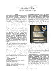
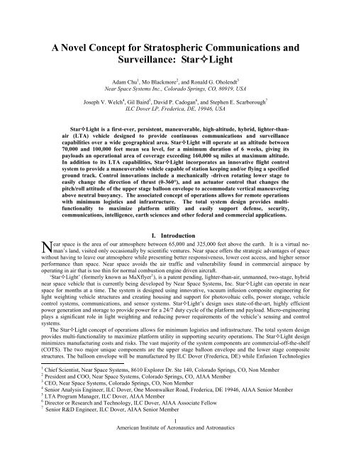
does not utilize a ballonet. The larger the airship plat<strong>for</strong>m, the more expensive it is to build, operate, and maintain.Larger airships are also more vulnerable to attack, weather and structural failure. One other key aspect of the upperstage is that it is a disposable, low cost envelope.Our research drove us to an ellipsoidal design due to the shape’s low drag characteristics and positive lift-to-dragratio throughout the range of anticipated pitch changes. The ellipsoidal shape minimizes frontal cross-sectional area(Figure 3) and rear wake size, while maximizing maneuverability against changing winds. The ellipsoidal shape ofthe upper stage is maintained at altitude by super-pressure of the helium gas and use of mass efficient internal shapecontrol spars/catenaries 2-6 . Extensive CFD analysis of the StarLight aerodynamics has been conducted, greatlyincreasing confidence in the superiority of the StarLight design.Frontal Cross-SectionalArea, m 220001800160014001200100080060040020000 20000 40000 60000 80000 100000SaucerBlimpSphereVolume, m 3Figure 3. Comparative Cross-Sectional Areas of Various Airship ShapesThe StarLight’s positive lift to drag ratio with positive pitch enables plat<strong>for</strong>m climbs above neutral buoyancyduring high wind surges. The altitude gained in the climb is used to accelerate the StarLight in a dive to recoverthe distance lost during the wind surge. The illustration in Figure 4 illustrates StarLight’s unique climb and divemaneuver that allows it to station keep when winds exceed thrust capability.5American Institute of Aeronautics and Astronautics
2. For wind > 30 knotsStarLight pitches upto maximum Cl/Cd.StarLight climbsabove neutral buoyancy3. At max Altitude gain,Lift=Gravity,StarLight will driftdownwind until windsurge passes4. StarLight will pitchdown to dive andaccelerate recoveringground distance lost indrift1. StarLight can resistwinds up to 30 knotsDirection of acceleration during diveNeutral Buoyancy AltitudeWind DirectionFigure 4. StarLight’s vertical maneuver is enabled by the aerodynamics of theupper stage balloon shape and functionality of the vehicle’s flight control systems,separating StarLight from other LTA conceptsA. Envelope DesignThe StarLight upper stage consists of the super pressure balloon envelope with its attachment lines andassociated load patches. The upper stage per<strong>for</strong>mance is critical in meeting certain operational system goals.Driving requirements <strong>for</strong> the upper stage are:1) Balloon shape lift and drag properties2) Inflated shape maintenance in all thermal environments3) Float altitude4) Structural integrity under maximum super-pressure5) Low cost, disposable design6) Materials durability and negation of pinholing (all flight phases)The lift and drag properties directly relate to the station keeping and maneuvering system requirements. Theupper stage balloon envelope must maintain positive differential pressure in order to achieve this ideal shape. Thechallenges <strong>for</strong> shape maintenance arise from the minimum cold state and the effect of leakage during operationallife. Float altitude is the traditional analysis trade <strong>for</strong> super pressure balloons. The maximum hot day at floataltitude determines maximum super pressure. This maximum super-pressure is used in the stress analysis of theupper stage envelope material, which would verify the structural integrity.There are several interactions and dependencies in the design calculations <strong>for</strong> super pressure balloons. In thecase of StarLight, the importance of the aerodynamic shape is added to these. In the per<strong>for</strong>mance of these analysesa best in class tool set was used including high fidelity CFD, Abaqus FEA, Navajo Trajectory 7 , and ThermalDesktop.The primary input to the patent pending envelope design was the discovery that ellipsoidal asymmetry plays asignificant role in overall aerodynamic per<strong>for</strong>mance. Parametric analysis of two primary functions, the envelopeheight-to-width ratio and the ratio of envelope volume above and below the equatorial chord line, revealed thatasymmetry in both areas contributed to the lowest drag coefficient with the highest lift coefficient. Both factorsrelate directly to per<strong>for</strong>mance in the upper atmosphere. A cross section plot of this ellipsoidal shape is shown inFigure 5. The challenge was to develop low stress inflatable shapes that came close to the theoretical shape, while atthe same time had acceptable weight. Design trades were conducted to develop potential envelope concepts. As6American Institute of Aeronautics and Astronautics
Figure 7. Inflated Table Top Model of the StarLightB. Aerodynamic AnalysisHigh fidelity analysis of the plat<strong>for</strong>m aerodynamics during development is critical to validating the design andincreasing the probability of successful achievement of per<strong>for</strong>mance requirements. For the aerodynamics of theupper stage the lowest possible drag coefficient was sought while maintaining a positive lift to drag ratio throughoutthe flight regime. Near Space Systems conducted internal computational fluid dynamics (CFD) analysis on the upperstage shape throughout the design process to validate or invalidate design characteristic and projected per<strong>for</strong>mance.In May, 2006, the United States Air Force approved a project to independently analyze the flight characteristics ofStarLight. Based on current mission needs, the government wanted to validate that the StarLight design couldsuccessfully operate in the cold, rarified environment of the earth’s stratosphere in a persistent manner. Theprocessing capability of the Major Shared Resource Center (MSRC) at Wright-Patterson Air Force Base in Dayton,Ohio allows significantly higher fidelity CFD analysis of StarLight than the earlier lower fidelity CFD modelingcould provide. The MSRC is a computational science facility supporting DoD research, development, test, andevaluation using high-per<strong>for</strong>mance computing and visualization. Critical aerodynamic per<strong>for</strong>mance factors wereused in the CFD modeling. Extensive resources in terms of CPU time have been devoted to this task. An exampleoutput of the simulations on the chosen upper stage shape is shown in Figure 8. These results, along with themanufacturing considerations, are the main reason that this particular shape concept was chosen. The results ofMSRC CFD analysis is a higher design confidence, an optimized balloon shape <strong>for</strong> maximum per<strong>for</strong>mance, andlower overall project risk.Figure 8. CFD Analysis of the StarLight Upper StageThe MSRC CFD analysis on the StarLight saucer shaped body is focused on how much drag and lift theaerodynamic lifting body presents to the wind as a function of angle of attack or pitch angle, altitude and windvelocity. Once these aerodynamic <strong>for</strong>ces were calculated, codes were developed to estimate the flight profile <strong>for</strong>maintaining loitering position relative to a fixed geographical location as a function of wind velocity and direction.The results of the CFD codes are critical to the assumption of either a laminar or a turbulent flow. The laminar8American Institute of Aeronautics and Astronautics
assumption results in higher (optimistic) lift to drag ratios <strong>for</strong> the different pitch angles. For the StarLight design,we used turbulent flow assumptions, the most conservative case. Using 3-D mesh models of the StarLight shape,below are the outputs (Figures 9-11) from the CFD calculations assuming the turbulent flow methodology.Figure 9 shows that pitch angles from zero degrees and higher results in positive lift. This means that theStarLight can pitch up to climb above neutral buoyancy using aerodynamic lift. Altitude gained above neutralbuoyancy is energy that is used to accelerate the StarLight in a dive allowing it to recover ground distance lost inhigh velocity wind surges. StarLight’s vertical maneuver is enabled by the aerodynamics of the upper stageballoon shape and functionality of the vehicle’s flight control systems, separating StarLight from other LTAconcepts.Total Lift ForceWindVelocity= 30knotsLift Force (nts) )150010005000-10 -5 0-5005 10 15 20-1000Pitch Angle (deg.)Figure 9. Lift Force vs. Pitch Angle at 30 KnotsFigure 10 shows the drag component <strong>for</strong> pitch angles with 30 knots of head wind. Notice that the drag remainslowest between minus 5 degrees nose low to 7 degrees nose high. This in<strong>for</strong>mation helps to identify pitch changesthat provide the highest lift to drag ratio. The higher the C L -C D ratio, the greater the climb above neutral buoyancy.Zero degrees of pitch provide the least amount of drag to maximize thrust.Total DragForceWindVelocity=30knotsDrag Force (nts)e (350300250200150100500-10 -5 0 5 10 15 20Pitch Angle (deg.)Figure 10. Drag Force Vs. Pitch Angle at 30 knots9American Institute of Aeronautics and Astronautics
Figure 11 shows the lift-to-drag ratio curve. A positive lift to drag ratio occurs when pitch is at zero degrees orhigher. Positive pitch will allow StarLight to climb above neutral buoyancy. In comparison, the results ofcalculations from a laminar assumption results in lift-to-drag ratios of higher than 5 <strong>for</strong> zero degrees of pitch angle,going up to about 10 at pitch angle of greater than 8 degrees.Lift to Drag RatioWind Velocity = 30 knots64Cl / Cd_20-10 -5-20 5 10 15 20-4-6Pitch Angle (deg.)Figure 11. Lift to Drag Ratio Vs. Pitch Angle at 30 knotsC. Envelope Material Selection and SizingHistorically, one of the greatest technical challenges to LTA design is developing an acceptable hull material thatmeets the programs mass, life, and cost constraints 8 . The envelope material must be able to withstand the day/nightand seasonal temperature changes at the operating altitude, in conjunction with the stresses and loads associated withoperation. It is also important to note that the material must be able to survive the dynamic effects of deployment,launch and ascent. For these reasons, and considering the harsh space-like environment at the altitudes between65,000 and 110,000 feet, our design approach is to use a commercially proven, multi-layered polyesterfilm/polyester fabric. Our team also chose to decline to use photovoltaics on any part of the balloon surface becauseof the thermal impact on the material. The other driver <strong>for</strong> selecting a polyester film/fabric <strong>for</strong> the envelope materialis cost, since the upper stage is disposable. Higher tenacity fibers such as Vectran or UHMWPE are available <strong>for</strong> usein the construction or lower mass materials, but at significantly higher cost. These higher cost fibers and laminatesare still in consideration, especially if they can provide a system level per<strong>for</strong>mance benefit such as longer endurance,but at this time polyester is the baseline fiber in the laminate.A parametric super-pressure hull sizing model was created <strong>for</strong> sensitivity studies. One important parametriccomponent of the sizing model is material selection. Model inputs include a table of potential material candidatesincluding their strengths and areal weight. The sizing model selects the best candidate material based on thestructural margin goals. An early investigation was to determine if commercial off the shelf (COTS) materials couldbe used <strong>for</strong> the upper stage envelope. COTS material laminates with a polyester tenacity of 4.5 gm/denier wereevaluated versus modified COTS laminates with a higher polyester tenacity of 8.3 gm/denier. The Modified-COTSmaterial design points were superior in terms of envelope weight by a large margin. The 3 layer lay-up of thebaseline polyester laminate material is shown in Figure 12.10American Institute of Aeronautics and Astronautics
Polyester Film, Clear, 0.5 milAdhesiveFabric, PolyesterFigure 12. Baseline Envelope Material Lay-upIn addition to cost and strength considerations, the hull material has also been selected <strong>for</strong> its low areal weight,low permeability, and its compatible with state-of-the-art airship envelope manufacturing processes. A polyesterfabric is used to provide strength in the warp and fill directions while a polyester film layer is bonded to the fabricusing an adhesive to create a barrier layer to contain the helium inflation gas. The baseline coated fabric hullmaterial has a tensile strength of 60-lbf/in in the warp direction and 120-lbf/in in the fill direction. Related UVexposure testing indicates that this hull material will have the endurance to withstand the UV environment above80,000 feet <strong>for</strong> the 6 week mission, as a similar material was originally selected as a candidate hull material <strong>for</strong> theAlternate Ultra-Long Duration Balloon (AULDB) concept 9 . The AULDB program had an intended mission durationof 100 days at 100,000 feet.One immediate outcome of the initial sizing model sensitivity runs was the strong influence that the maximumtemperature increase has on the size and weight of the envelope. Accordingly, one of the main objectives <strong>for</strong> thisinitial model was to estimate the maximum diurnal increase in temperature. The thermal analyses were run at vernalequinox with latitudes between 0 and 45 degrees. The estimate <strong>for</strong> maximum temperature increase wasapproximately 32C and came from a run with 0 degree latitude. A plot of the helium temperature <strong>for</strong> this case isshown in Figure 13. This value of diurnal temperature increase was an important input <strong>for</strong> subsequent sizing andstress analysis modeling. It was found that the temperature results from the thermal analysis were in good agreementwith those from the trajectory modeling. As part of the trajectory modeling, the diurnal temperature result was usedto calculate the pressure change in the balloon envelope as shown in Figure 14.The sizing model contains a first order <strong>for</strong> maximum stress in the upper stage under a uni<strong>for</strong>m inflation pressure.A more detailed stress prediction is needed to support the design ef<strong>for</strong>t of the upper stage. A finite element modelwas constructed <strong>for</strong> the upper stage with the intent of evaluating stresses due to maximum super pressure. A quartersymmetry model was constructed <strong>for</strong> this task. The mesh <strong>for</strong> this model is shown in Figure 15 along with someprinciple stress contour results. The results indicated that the first order calculation in the preliminary sizing modelwas over predicting stress by a small margin. The sizing model <strong>for</strong> the upper stage was updated with this moredetailed stress prediction.11American Institute of Aeronautics and Astronautics
-20Temperature (C)-30-40-500 0.5 1 1.5 2Time (days)Figure 13. Hot Case Helium Temperature from Thermal Desktop Model3750Pressure (Pa)35003250300027500 0.5 1 1.5 2Time (days)Figure 14. Hot Case Gas Pressure @ Float12American Institute of Aeronautics and Astronautics
Figure 15.Finite Element Model Mesh and Sample Principle Stress ContoursV. Launch and DeploymentStarLight is launched using an “out-of-the-box” technique. The upper stage and the lower stage would bedelivered to the launch site in two separate containers via ground, sea, or air transportation. The upper stage ispacked in an umbrella / Z-folded configuration that allows the top center of the envelope to remain at the top of theshipping container. The top center of the envelope is where the helium valves are located and this will also be thelocation where the helium will be introduced into the vehicle. The payload lines are located at the bottom of thecontainer, but can be attached to the lower stage. The payload lines are attached to the upper stage at a specifieddistance from the outer edge of the envelope in twelve locations. Once the upper stage and the lower stage areattached, a support net or a crane is used to control the motion of the upper stage as helium is introduced into theenvelope. Three sleeves, are wrapped around the envelope in various locations (and are later released by remoteactuation) during packing are used to control thehelium bubble and limit loose material exposure to thewind during inflation. In this manner only the topcenter of the envelope is filled with helium. Once thecharging is complete and the upper tethering net/craneare removed and the helium filling tube is detached.The partially inflated envelope will be tethered usingthree guy lines attached to the upper collar, similar tothat used in the logging balloon application in Figure16. This will provide control of the inflated systemuntil ready <strong>for</strong> release, and facilitate operations in lowwind conditions. Once the upper stage is extendedover the lower stage and the system is checked, thecollars are released and ascent beginsThe system will ascend as a zero pressure balloonand would not reach the fully evolved aerodynamicshape until it reaches an altitude near the float altitude.As the system ascends, the deployment is analogous tothat of a parachute and any extra helium gas is ventedon the way up. Suspension line attachments to theoutboard location of the envelope provide naturalbalance and stability to the system during shapeevolution. Launch and deployment of the system areconsidered risk areas of any balloon launch and adetailed test plan has been developed utilizing thelaunch of various sub-scale models to validate these processes <strong>for</strong> the StarLight.Figure 16. ILC Dover Manufactured LoggingBalloon Supported by Ground TethersFor vehicle recovery at the end of a mission, lifting gas is vented at a controlled rate <strong>for</strong> controlled descent of theentire vehicle. At the appropriate descent altitude, the upper and lower stages are disconnected and a GPS-guidedparachute is deployed from the lower stage <strong>for</strong> controlled landing in a designated location. The gas depleted upperstage lands in a designated area in the vicinity of the lower stage.13American Institute of Aeronautics and Astronautics
VI. ConclusionThe StarLight hybrid LTA vehicle can provide continuous communications and surveillance capabilities at70,000 to 100,000 feet at a significantly lower total cost than comparable space-based plat<strong>for</strong>ms. The concept isunique from other high altitude LTA vehicles because it utilizes a two stage design where the upper stage is a liftingbody. This two stage design provides a number of per<strong>for</strong>mance benefits including: separating the solar cells from theenvelope hull and payload modularity. Also, the upper stage envelope is a low cost disposable balloon, while thelower stage is recovered. The lifting body shape of the upper stage allows the system to fly above the neutralbuoyancy point during wind gusts and dash back to the target area after the wind gusts have subsided. The systemdesign is also unique because a great majority of the materials are commercial-off-the-shelf, thereby reducingdevelopment time and costs. The development of the StarLight has been advanced significantly recently throughenvelope material selection as well as detailed thermal, aerodynamic, trajectory, and sizing analysis.AcknowledgmentsThe authors thank Dr. Hugh Thornburg of MSRC at Wright-Patterson AFB AFRL <strong>for</strong> all of his supportconducting the CFD analysis during the past year.References1 Scott, W. B., “<strong>Novel</strong> hybrid near-space plat<strong>for</strong>m awaits a visionary financial angel,” Aviation Weekly and SpaceTechnology, Page 60, January 30, 2006.2 Cadogan, D.P. Smith, T., Lee, R., Scarborough, S.E., Graziosi, D. “Inflatable and Rigidizable Wing Components <strong>for</strong>Unmanned Aerial Vehicles,” AIAA-2003-1801, 44th AIAA/ASME/ ASCE/AHS/ASC Structures, Structural Dynamics, andMaterials Conference and Exhibit AIAA Gossamer Spacecraft Forum, Norfolk, VA, April 7-10, 2003.3 Simpson, A. Santhanakrishnan, J. Jacob, S. Smith, J. Lumpp, D. Cadogan, M. Mackusick, S. Scarborough, “Flying on Air:UAV Flight Testing with Inflatable Wing Technology”, AIAA-2004-6570 AIAA 3rd "Unmanned Unlimited" TechnicalConference, Workshop and Exhibit, Chicago, Illinois, Sep. 20-23, 2004.4 Rowe, J.M., Smith, S.W., Simpson, A., Jacob, J., Scarborough, S.E., “Development of a Finite Element Model of WarpingInflatable Wings ,” AIAA-2006-1697, 47th AIAA/ASME/ASCE/AHS/ASC Structures, Structural Dynamics and MaterialsConference, Newport, Rhode Island, May 1-4, 2006.5 Smith, S.W., Jacob, J., Jones, R.J., Scarborough, S.E., Cadogan, D.P., “A High-Altitude Test of Inflatable Wings <strong>for</strong> Low-Density Flight Applications,” AIAA-2006-1696, 47th AIAA/ASME/ASCE/AHS/ASC Structures, Structural Dynamics andMaterials Conference, Newport, Rhode Island, May 1-4, 2006.6 Cadogan, D.P., Scarborough, S.E., Gleeson, D., Dixit, A, Jacob, J., Simpson, A. “Recent Development and Test of InflatableWings,” AIAA-2006-2139, 47th AIAA/ASME/ASCE/AHS/ASC Structures, Structural Dynamics and Materials Conference,Newport, Rhode Island, May 1-4, 2006.7 Pankine, Alexey A., Heun, Matthew K., Nguyen, Nam and Schlaifer, R. Stephen. “NAVAJO: Advanced Software Tool <strong>for</strong>Balloon Per<strong>for</strong>mance Simulation,” AIAA 2005-7411, AIAA 5 th Aviation, Technology, Integration, and Operations Conference(ATIO), Arlington, VA, September 26-28, 2005.8 Miller, T., and Mandel, M. “Airship Envelopes: Requirements, Materials, and Test Methods,” ILC Dover Publication, 2002.9 Welch, J.V., Wang, S., Blandino, J. R., McEvoy, K., “Super Pressure Balloon Non-Linear Structural Analysis andCorrelation using Photogrammetric Analysis,” AIAA-2005-7447, AIAA 5th Aviation, Technology, Integration, and OperationsConference(ATIO) 16th Lighter-Than-Air Systems Technology Conference and Balloon Systems Conference, Arlington, VA,September 26-28, 2005.14American Institute of Aeronautics and Astronautics