Eurocode 4 â EN 1994
Eurocode 4 â EN 1994
Eurocode 4 â EN 1994

Create successful ePaper yourself
Turn your PDF publications into a flip-book with our unique Google optimized e-Paper software.
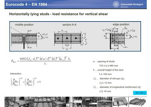
<strong>Eurocode</strong> 4 – <strong>EN</strong> <strong>1994</strong>Horizontally lying studs - load resistance for vertical shearmiddle positionsection A-AAedge positionPRd , VInteraction:0.012012⋅0.50.4 0.3 '( fd) ( da/s) ( d) ( a)0.7cksl r,o v= a …spacing of studs1.2⎛ F ⎞ ⎛d ,L F+⎜P ⎟⎜Rd ,L ⎠ ⎝Pd V,⎝ Rd V,⎞⎟⎠1.2≤ 1γvk110 ≤ a ≤ 440 mmh …overall height of the studh ≥ 100 mm∅ s … diameter of stirrups (d s )∅ s ≥ 12 mm∅ l … diameter of longitudinal reinforment (d l )∅ l ≥ 16 mm<strong>EN</strong> <strong>1994</strong>-2
<strong>Eurocode</strong> 4 – <strong>EN</strong> <strong>1994</strong>Detailing of headed studsAdvices for distances of studs (edge distance, spacing of studs)Hanswille
<strong>Eurocode</strong> 4 – <strong>EN</strong> <strong>1994</strong>Detailing of headed studs - uplift forcesCalculation of uplift forces due to longitudinal shear forceHanswille
<strong>Eurocode</strong> 4 – <strong>EN</strong> <strong>1994</strong>Longitudinal shear forces in concrete slab – determinationSlab in compressionSlab in tensionHanswille
<strong>Eurocode</strong> 4 – <strong>EN</strong> <strong>1994</strong>Longitudinal shear forces in concrete slab – strut-and-tieHanswille
<strong>Eurocode</strong> 4 – <strong>EN</strong> <strong>1994</strong>Longitudinal shear forces in concrete slab – shear planesection a-a:section b-b, c-c, d-d:with L v = L b-b , L c-c , L d-dA cv = h c a vA cv = L v a vHanswille
Table of contentPart 1: Slim-floor system1. Slim-floor systems: Application / range of application1.1 Slim-floor systems without composite action1.2 Slim-floor systems with composite action2. Design2.1 General rules for design of slim-floor girder (application of <strong>EN</strong><strong>1994</strong>-1-1)2.2 Design (ultimate limit state)2.2.1 Design of girder2.2.2 Design of slab223D 2.2.3 Design of studs2.2.4 Erection condition2.3 Fire design - advices2.4 Design (service limit state)2.4.1 Deflection2.4.2 Proposal for vibration design2.5 Technical Solutions of connections2.6 Design example Ultimate limit state, service limit state, design of joints and connections
Slim-floor systemsErection conditions – structural behaviourDifferent stress distribution due to the erection and propping conditionsDifferent conditions:- unpropped condition- propped condition- propped condition and jacking propsHanswille
Slim-floor systemsErection conditions – structural behaviourUnpropped pp construction (A)Propped construction (B)Propped construction and jacking of props (C)The bending capacity M pl,Rd is independent of the loadingphistory in case of Class 1 or Class 2 cross sections (plasticdesign)Using Class 3 or Class 4 cross sections the elastic behavior ofthe loading history has to be taken into account in ULSHanswille
Table of contentPart 1: Slim-floor system1. Slim-floor systems: Application / range of application1.1 Slim-floor systems without composite action1.2 Slim-floor systems with composite action2. Design2.1 General rules for design of slim-floor girder (application of <strong>EN</strong><strong>1994</strong>-1-1)2.2 Design (ultimate limit state)2.2.1 Design of girder2.2.2 Design of slab223D 2.2.3 Design of studs2.2.4 Erection condition2.3 Fire design - advices2.4 Design (service limit state)2.4.1 Deflection2.4.2 Proposal for vibration design2.5 Technical Solutions of connections2.6 Design example Ultimate limit state, service limit state, design of joints and connections
<strong>Eurocode</strong> 4 – <strong>EN</strong> <strong>1994</strong>Fire design - General• Fire protection can be divided into „active“ and „passive“ solutions• „active“ fire protection: surveillance methods and extinction concepts (fire sprinkling & fire alarm system)• „passive“ fire protection: structural measures (fire design according to <strong>EN</strong> <strong>1994</strong>-1-2)Possibilities of „passive“ fire protection:• conventional fire protection (fire protection casing)• fire design without additional structural measures• fire design with additional structural measures (i.e. additional reinforcement)additional reinforcement (fire design)Fire design with additional structural measures („integrated fire protection“)‣Useful and efficient method if design (section) of slim-floor girder not sufficent‣ additional reinforcement balances the reduced strength of the steel section due to fire (rising temperature)
<strong>Eurocode</strong> 4 – <strong>EN</strong> <strong>1994</strong>Fire design – according to <strong>EN</strong> <strong>1994</strong>-1-2<strong>EN</strong><strong>1994</strong>-1-2 1 allows three design procedures:1) recognized design solutions called tabulated data for specific types of structural members (4.2)2) simple calculation models for specific types of structural members (4.3)3) advanced calculation models for simulating the behavior of the global structure (4.3)1) Tabulated data solutiondesign solutions for single components / specific types of structural members• tables with minimum size• minimum concrete covering• additional reinforcement for fire resistanceApplication for- composite beam comprising steel beam with partial concrete encasement- composite columns
<strong>Eurocode</strong> 4 – <strong>EN</strong> <strong>1994</strong>Fire design – according to <strong>EN</strong> <strong>1994</strong>-1-22) Simplified calculation modeldesign solutions for single components / structural members• reduction of material strength due to temperatur• design moment resistance M fi,t,Rd :Application for- composite deck slabs- composite girder (steel section protected and unprotected)- composite beam comprising steel beam with partial concrete encasement-composite columnsadditional reinforcement (fire design)„ULS“ „fire design“ <strong>EN</strong> <strong>1994</strong>-1-2
<strong>Eurocode</strong> 4 – <strong>EN</strong> <strong>1994</strong>Fire design – according to <strong>EN</strong> <strong>1994</strong>-1-23) Advanced calculation model- model may be used for individual members, for subassemblies or for entire structures- models may be used with any type of cross-section- model considers material, structural and geometrical properties due to fire impactNumerical model: fire design of slim-floor girder with- - UPE-profile (with hollow core)- - IFB-profile <strong>EN</strong> <strong>1994</strong>-1-2
Table of contentPart 1: Slim-floor system1. Slim-floor systems: Application / range of application1.1 Slim-floor systems without composite action1.2 Slim-floor systems with composite action2. Design2.1 General rules for design of slim-floor girder (application of <strong>EN</strong><strong>1994</strong>-1-1)2.2 Design (ultimate limit state)2.2.1 Design of girder2.2.2 Design of slab223D 2.2.3 Design of studs2.2.4 Erection condition2.3 Fire design - advices2.4 Design (service limit state)2.4.1 Deflection2.4.2 Proposal for vibration design2.5 Technical Solutions of connections2.6 Design example Ultimate limit state, service limit state, design of joints and connections
<strong>Eurocode</strong> 4 – <strong>EN</strong> <strong>1994</strong>SLS design (serviceability limit states) - GeneralDesign according to SLS:- limitation of stresses- crack width control- limitation of deflections- vibrations
<strong>Eurocode</strong> 4 – <strong>EN</strong> <strong>1994</strong>SLS design (serviceability limit states) – Limitation of stresses‣ Serviceability assures the unrestricted application of building components‣ depending on the application the design rules (combinations) variescharacteristic combination: Ed= E { ∑ Gk,j+ Pk+ Qk,1+ ∑ ψ0,iQk,i }frequent combination: E E { ∑ G + P + ψ Q + ∑ ψ Q }d = k,j k 1,1 k,1 2,i k, iquasi-permanent combination: i E E{ ∑ G + P + ∑ ψ Q}d = k,j k 2,i k, iε yεf yσ yσ cσ c > σ ctcombination stress limitrecommendedvalues k iε = ε s,Flσ > σ ct structural steel characteristic σ Ed ≤ k a f yk k a = 100 1,00reinforcement characteristic σ Ed ≤ k s f sk k s =0,80Limitation of stressesdepending on structural material:f yε σ y σ c concrete characteristic σ Ed ≤ k c f ck k c = 0,60headed studs characteristic P Ed ≤ k s P Rd k s =0,75
<strong>Eurocode</strong> 4 – <strong>EN</strong> <strong>1994</strong>SLS design (serviceability limit states) – Crack width controlCrack control according design rules <strong>EN</strong>1992-1-1Recommended values for w maxwExposureclassreinforced members,prestressed members withunbonded tendons andmembers prestressed bycontrolled imposeddeformationsprestressedmembers withbonded tendonsquasi - permanentfrequent loadload combinationcombinationN sεε sε cN sXO, XC1 0,4 mm (1) 0,2 mmσL esL esXC2, XC3,XC40,2 mm (2)Δσ sXD1,XD2,XS1,XS2,XS30,3 mmdecompressionσ c,1σ sσ s,1L esL esHanswille
<strong>Eurocode</strong> 4 – <strong>EN</strong> <strong>1994</strong>Exposure classes according to <strong>EN</strong> 1992-1-1Class Description of environment ExamplesXOfor concrete without reinforcement, forconcrete with reinforcement : very dryno risk of corrosion or attackconcrete inside buildings with very low air humidityCorrosion induced by carbonationXC1 dry or permanently wet concrete inside buildings with low air humidityXC2 wet, rarely dry concrete surfaces subjected to long term water contact, foundationsXC3 moderate humidity external concrete sheltered from rainXC4 cyclic wet and dry concrete surfaces subject to water contact not within class XC2Corrosion induced by chloridesXD1 moderate humidity concrete surfaces exposed to airborne chloridesXD2 wet, rarely dry swimming pools, members exposed to industrial waters containingchloridesXD3 cyclic wet and dry car park slabs, pavements, parts of bridges exposed to spray containingCorrosion induced by chlorides from sea waterXS1 exposed to airborne salt structures near to or on the coastXS2 permanently submerged parts of marine structuresXS3 tidal, splash and spray zones parts of marine structuresHanswille
Table of contentPart 1: Slim-floor system1. Slim-floor systems: Application / range of application1.1 Slim-floor systems without composite action1.2 Slim-floor systems with composite action2. Design2.1 General rules for design of slim-floor girder (application of <strong>EN</strong><strong>1994</strong>-1-1)2.2 Design (ultimate limit state)2.2.1 Design of girder2.2.2 Design of slab223D 2.2.3 Design of studs2.2.4 Erection condition2.3 Fire design - advices2.4 Design (service limit state)2.4.1 Deflection2.4.2 Proposal for vibration design2.5 Technical Solutions of connections2.6 Design example Ultimate limit state, service limit state, design of joints and connections
<strong>Eurocode</strong> 4 – <strong>EN</strong> <strong>1994</strong>Deflection of slim-floor girder systemsDeflections due to loading applied to the composite member should be calculatedusing elastic analysis taking into account effects from- cracking of concrete- creep and shrinkage- sequence of construction- influence of local yielding of structural steel at internal supports
<strong>Eurocode</strong> 4 – <strong>EN</strong> <strong>1994</strong>Deflection of slim-floor girder systemsDifferent deflection behavior of”normal height” composite girder and composite slim-floor girder due to cracking of theconcrete chordcomp. section I i,0 comp. section I EI ? EI ?i,0steel section I i,AEI ?0,85 l 0,15 lll??? ???llSimplified calculation method for composite girderaccording to <strong>EN</strong><strong>1994</strong>-1-1Different deflection behaviour of slim-floor girder –calculation method according to <strong>EN</strong><strong>1994</strong> still valid?
<strong>Eurocode</strong> 4 – <strong>EN</strong> <strong>1994</strong>Deflection of slim-floor girder systemsDifferent deflection behaviour of”normal height” composite girder and composite slim-floor girder due to cracking of theconcrete chordcomp. section I i,0 comp. section I EI ? EI ?i,0steel section I i,AEI ?0,85 l 0,15 lll??? ???llSimplified calculation method for composite girderaccording to <strong>EN</strong><strong>1994</strong>-1-1Different deflection behaviour of slim-floor girder –calculation method according to <strong>EN</strong><strong>1994</strong> still valid?
Table of contentPart 1: Slim-floor system1. Slim-floor systems: Application / range of application1.1 Slim-floor systems without composite action1.2 Slim-floor systems with composite action2. Design2.1 General rules for design of slim-floor girder (application of <strong>EN</strong><strong>1994</strong>-1-1)2.2 Design (ultimate limit state)2.2.1 Design of girder2.2.2 Design of slab223D 2.2.3 Design of studs2.2.4 Erection condition2.3 Fire design - advices2.4 Design (service limit state)2.4.1 Deflection2.4.2 Proposal for vibration design2.5 Technical Solutions of connections2.6 Design example Ultimate limit state, service limit state, design of joints and connections
SLS – floor vibrationProposals for vibration designDue to the shallow construction height slim-floor girders are sensitive to the vibration behavior!Calculation/Analysis of deck vibration:- finite element calculation method- simplified calculation methods (design guide)
SLS – floor vibrationVibration – <strong>EN</strong><strong>1994</strong><strong>EN</strong> <strong>1994</strong>-1-1: 1 1:The dynamic properties of floor beams should satisfy the criteria in <strong>EN</strong> 1990, A.1.4.4<strong>EN</strong> 1990, A1.4.4:To achieve satisfactory vibration behavior of buildings and their structural members under serviceability conditions, thefollowing aspects, among others, should be considered:the comfort of the userthe functioning of the structure or its structural membersOther aspects should be considered for each project and agreed with the client!The natural frequency of vibrations of the structure or structural member should be kept above appropriate values!These values depend upon the function of the building and the source of the vibration, and agreed with the client and/or therelevant authority.Possible sources of vibration that should be considered include walking, synchronised movements of people, machinery,ground borne vibrations from traffic and wind actions.Further information is given in ISO 10137.
SLS – floor vibrationVibration – <strong>EN</strong><strong>1994</strong>The pacing rate f s dominates the dynamic effects and the resulting dynamic loads. The speed of pedestrian propagation v s isa function of the pacing rate f s and the stride length l s .pacing ratef s[Hz]forwardspeedv s = f sl s[m/s]stridelength l s[m]slow walk ∼1,7 1,1 0,6normal walk ∼2,0 1,5 0,75fast walk ∼2,3 2,2 1,00slow running (jog) ∼2,5 3,3 1,30fast running (sprint) > 3,2 5,5 1,75Hanswille
SLS – floor vibrationProposals for vibration designReferenced to:Design guide for floor vibrations:The design guide focuses on simple methods, design tools andrecommendations for the acceptance of vibration of floors whichare caused dby people during normal use.Damping DDamping is the energy dissipation of a vibratingsystem. The total t damping consists of- Material and structural damping,- Damping by furniture and finishing (e.g. false floor),- Spread of energy throughout the whole structure.Modal mass A system with several degrees of freedom can beM modreduced to a system with a single degree of freedomArcelorMittal: Design Guide for Floor Vibrations
SLS – floor vibrationProposals for vibration designDesign guide for floor vibrations:Naturalfrequency f(Eigengfrequenz)Every structure has its specific dynamic behavior with regards to shape and duration T[s] of aEigenfrequency single oscillation. The frequency f is the reciprocal of the oscillation time T (f = 1/T).Each structure has as many natural frequencies and associated mode shapes as degrees offreedom. They are commonly sorted by the amount of energy that is activated by the oscillation.Therefore the first natural frequency is that on the lowest energy level and is thus the most likelyto be activated.The equation for the natural frequency of a single degree of freedom system isArcelorMittal: Design Guide for Floor Vibrations
SLS – floor vibrationProposals for vibration designDesign guide for floor vibrations:OS-RMS 90One step RMS- value of the velocity for a significant step covering the intensity of 90% ofpeople’s p steps walking normallyOS: One stepRMS: Root mean square = effective value, here of velocity vFor concrete, the dynamic modulus ofelasticity should be considered to be 10%higher than the static tangent modulus E cm .In the determination of the dynamicfloor characteristics, a realistic fractionof imposed load should be consideredin the mass of the floor. Experiencedvalues for residential and office buildingare 10% to 20% of the imposed load.ArcelorMittal: Design Guide for Floor Vibrations
SLS – floor vibrationProposals for vibration designDesign guide for floor vibrations:Detemination of damping:ArcelorMittal: Design Guide for Floor Vibrations
SLS – floor vibrationProposals for vibration designDesign guide for floor vibrations:Classification of vibrations:The perception of vibrations is a very individual problem that can only be described ina way that fulfills the acceptance of comfort of the majority.Aiming at an universal assessment procedurefor human induced vibration, it is recommendedto adopt the so-called one step RMS value (OS-RMS) as a measure for assessing annoyingfloor vibrations. The OS-RMS valuescorrespond to the harmonic vibration caused byone relevant step onto the floor.Classification of floor response andrecommendation for the application ofclassesArcelorMittal: Design Guide for Floor Vibrations
SLS – floor vibrationProposals for vibration designArcelorMittal: Design Guide for Floor VibrationsDesign guide for floor vibrations:Application of diagrams:When modal mass and frequency are determined, the OS-RMS90-value as well as the assignment to the perceptionclasses may be determined with the diagrams given below.The relevant diagram needs to be selected according to thedamping characteristics of the floor in the condition ofuse (considering finishing and furniture).The diagram is used by entering on the x-axis the modalmass and the corresponding frequency on the y-axis axis. TheOS-RMS value and the acceptance class can be read-off atthe intersection of extensions at both entry points.
SLS – floor vibrationProposals for vibration designDesign guide for floor vibrations:Determination of Natural frequency:Orthotropic floors as e.g. composite floors with beams in longitudinal direction and a concrete plate in transversedirection have different stiffnesses in length and width (EIy>EIx). The first natural frequency of the orthotropic plate beingsimply supported at all four edges can be determined with:ArcelorMittal: Design Guide for Floor Vibrations
SLS – floor vibrationProposals for vibration designDesign guide for floor vibrations:Determination of Natural frequency (self-weight approach):The self weight approach is a very practical approximation in cases where the maximum deflection δmax due toself weight loading is already determined, e.g. by finite element calculation. This method has its origin in the generalfrequency equation:The stiffness K can be approximatedby the assumption:The approximated natural frequency isArcelorMittal: Design Guide for Floor Vibrations
SLS – floor vibrationProposals for vibration designDesign guide for floor vibrations:Determination of Modal Mass:Plate spans uniaxial between beams, plate and beams simply supportedModal massArcelorMittal: Design Guide for Floor Vibrations
Table of contentPart 1: Slim-floor system1. Slim-floor systems: Application / range of application1.1 Slim-floor systems without composite action1.2 Slim-floor systems with composite action2. Design2.1 General rules for design of slim-floor girder (application of <strong>EN</strong><strong>1994</strong>-1-1)2.2 Design (ultimate limit state)2.2.1 Design of girder2.2.2 Design of slab223D 2.2.3 Design of studs2.2.4 Erection condition2.3 Fire design - advices2.4 Design (service limit state)2.4.1 Deflection2.4.2 Proposal for vibration design2.5 Technical Solutions of connections2.6 Design example Ultimate limit state, service limit state, design of joints and connections
Connections / Joints with slim-floor girderConnections to coloums & girdersGeneral- Exemplarily the connections are shown for hat-profiles (UPE-profiles)- Constructions / joints with I-profiles or any other types of slim-floor girder can be done similarly- in principle the joints can be executed- constrained- hinged- normally the connections will be executed hinged,so that the slim-floor girder acts as a single-span girder- constrained joints have the advantage of areduced deflection of the girder system
Connections / Joints with slim-floor girderEnd-plate joints – hinged connection• joints between steel girder connections to columns with I-profiles• the end-plates are directly bolted to the colomns flanges• only shear forces (no transfer of bending moments)• as the bolts are protected by the deck concrete of the slim-floor girder: high fire resistance of the connectionViewSection A - AAa2t S,ft SthSthce1 ee1a3a1ortT,fe2e3e2AbStHinged end-plate jointbS
t T,fhStConnections / Joints with slim-floor girderEnd-plate joints – hinged connectionErection:• end-plates are welded to the slim-floor beams (openings to drill holes)• fast erection (reduced crane times) possible by clipping the girdersto the columns (openings of drill holes)ViewASection A - Ahcthreaded bart Stopening duringerectiondetail of end-plateAb StHinged end-plate connection (prepared for fast clipping)bS
Connections / Joints with slim-floor girderEnd-plate joints – hinged connectionErection of several slim-floorg girders in series:• for the compensation of the tolerances placing of additional lining plates between column flange and end-plate• gap between slim-floor girder and column flange (fire resistance!)ViewSection A - Alining platesa2t S,ft StAhSthce1e e1a3gap sa1AortT,fe2e3e2bStHinged end-plate connection with additional lining plates for the erection tolerancebS
Connections / Joints with slim-floor girderEnd-plate joints – constrained connection• continuous girder action by reinforcement in tension zone (top side ot the concrete deck)• contact piece & stiffener in the compression zone of the column• during erection: single-span girder action (only transfer of shear force)• after hardening process of concrete: continuous girder actionViewSection A - Areinforcementt St,St St,TAopening incolumntS,SttT,fhSthcstiffener a1a2AConstrained connection (continuous action by reinforcement)bSt
Connections / Joints with slim-floor girderEnd-plate joints – constrained connection• continuous girder action by constrained end-plate joint and reinforcement• contact piece & stiffener in the compression zone of the column• during erection: already partial continuous girder action (by constrained end-plate)• after hardening process of concrete: full continuous girder actionViewSection A - Aa2t Stt StAerection boltshSt,1hchSt,2a 1t S,sorT,ftAConstrained end-plate joint
Connections / Joints with slim-floor girderConnection to constricted columns• due to constricted columns four and more girder can be seated• after erection of the girder the bearing area of the column will be concreted• the bearing of the girder is protected against fire impact• the eccentricity of the shear force from the girder is minimizedViewSection A - AAhN,otT,fhcfhStAdSsecuring bolt(during erection)bStbSHinged connection toconstricted column
Connections / Joints with slim-floor girderCleat connection – hinged connection• cleat connections allow a very fast erection• cleat connections are characterized by a high pre-fabrication• cleat connection allow a higher tolerance in fabrication• cleat can be welded directly to the column flange below the slim-floor girderViewSection A - AAst Sthca3ora1hN,uΔh NhKhN,otT,fa2AtK80 mm (required for fire design)bKbsHinged cleat connection