Feltest FiberScanâ¢
Feltest FiberScanâ¢
Feltest FiberScanâ¢

Create successful ePaper yourself
Turn your PDF publications into a flip-book with our unique Google optimized e-Paper software.
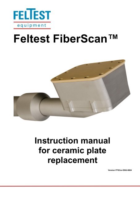
<strong>Feltest</strong> FiberScanInstruction manualfor ceramic platereplacementVersion FFSCer-ENG-0804
REPLACING THE CERAMIC SENSOR PLATEWARNING!Do not use a damaged rubber “O”-ring, as it will impair the sensors protection,resulting in costly damages to the microwave sensor!WARNING!Do not touch the microwave sensor surface for any reason!WARNING!It is very important NOT to tighten the screws all the way down in one step, but toGRADUALLY turn one screw until the “resistance” becomes slightly higher and thengo to the next screw.WARNING!All the following steps are at the operator’s risk. <strong>Feltest</strong> Equipment BV take no liabilityfor improper installation of the ceramic plate.The FiberScan TM has been engineered for an easy ceramic plate replacement, without theneed to send it in.In order to safely apply a new ceramic foil, please follow the next steps:Step 1 – remove the damaged ceramic plateLoosen and remove the screws in theceramic plate.Carefully remove the damaged ceramic platefrom the sensor head. The plate might stick alittle to the sensor housing, due to the threadlocking material (like Loctite or similarproducts).Figure 1 - Removing the ceramic plate2
The ceramic plate is pushed against a silicone “O”-ringunderneath to ensure the right waterproof level.Gently remove the thread locking residues around eachscrew hole. Be careful not to damage “O”-ring!Make sure the microwave sensor surface is completelydry. If it is not, please blow gently a little bit of CLEANcompressed air on its surface. If in doubt if waterpenetrated the sensor's interior, leave the sensorhousing open for at least 24 hours in a warm and dryplace.Figure 2 - The microwave sensor and the black "O"-ringStep 2 – preparation of the new ceramic plateMake sure that the hole indicated in figure 45 containsheat conductive paste, to improve the heat exchangebetween the ceramic sensor plate and the build-intemperature sensor.WARNING: if the heat conductive paste is not used, theFiberScan will not be able to achieve it's normalaccuracy.Figure 3 - The hole for the temperature sensorStep 3 – installation of the new ceramic platePosition the new ceramic plate on the sensor housing,taking care that the mounting holes in the ceramic platecoincide with mounting holes in the metal housing.The temperature sensor (as indicated in figure 42)should fit into the according hole of the ceramic plate(as indicated in figure 41).Figure 4 - Watch the temperature sensor!3
Put a small drop of a thread locking material (likeLoctite 222 or similar) into the mounting holes, toavoid that the screws will come loose easily.Do not use too strong glues to make sure that thescrews still can be loosened when the ceramic plateneeds to be removed again.Figure 5 - Applying the thread locking materialThe screws must be tightened very carefully, too muchforce or tension will crack the ceramic. Therefore thescrews must be tightened gradually and one-by-one, asindicated in figure 48.As soon as the needed force increases, go to the nextscrew and work your way around all the screws in atleast 3 times. NEVER tighten one screw all the way andthen go to the next, this will surely damage the ceramicplate!Figure 6 - Slightly tighten the screws one-by-oneIMPORTANT: when the required force becomes higher,stop turning the screws immediately! Look at thedistance between the ceramic plate and the metalsensor housing: when the ceramic is in direct contactwith the metal housing, the "O"-ring is fully compressedand the screws cannot be tightened any further!The applied torque on the screws should be between0.5 and 0.7 N/m. This can be checked with specialtools, as shown in figure 49.Figure 7 – The applied torque may not exceed 0.7 N/mAfter the installation of a new ceramic plate a new calibration must be started.4
INSTRUMENT CALIBRATION (SET UP > CALIBRATION)With the calibration procedure it is possible to verify the calibration of the sensor and ifnecessary, to perform a re-calibration with the supplied special S glass plate.The FiberScan works with two calibrations: a factory calibration that takes more than 5 hoursin our specialized laboratory and a local calibration that is used to compensate for smalldeviations due to local circumstances like (stock) temperature. The calibration menu (part ofthe Setup menu) of the FiberScan refers to this local calibration.The calibration influences the accuracy of the FiberScan, therefore carefully read thefollowing remarks.IMPORTANT!For the best accuracy it is advised to first bring the sensor head to workingtemperature (the temperature of the stock by keeping the sensor head in the whitewater) and then execute the calibration procedure, especially if the workingtemperature is close to the working limits of the instrument.CAUTION!Before proceeding, please make sure that the sensor surface is completely dry andclean, free from any residue.CAUTION!For a calibration the sensor needs to be in an area free of disturbances. Make surethat the sensor head is at least 50cm away from metallic objects and/ortelecommunication equipment like mobile phones. As the human body contains alot of water, also people should keep the distance. See figure 31.Figure 8 – Minimum free zone during calibration5
CAUTION!If the procedure is not correctly executed, the instrument can give less accurate testresults.CAUTION!The reference glass plate is placed correctly when the centre of the glass is on thecentre of the sensor head, as shown in figure 32.Figure 9 - Position of the glass plate on the sensor headBefore starting the calibration procedure please:1. verify that the sensor is correctly connected to the control unit (see paragraph 3.1 of the<strong>Feltest</strong> FiberScan instruction manual).2. set the Speed/Accuracy to 1 for best accuracy (see paragraph 4.6.1 of the <strong>Feltest</strong>FiberScan instruction manual).The calibration procedureUse the UP and DOWN buttons to move the cursor to the Set up menu item and press E toaccess it. Select the “calibration” option and the following screen is shown:Figure 10 - Starting the calibration verification procedure6
When the reference glass plate (or "tile") is placed according to the instructions above, pressthe measurement button to verify the calibration. After the verification procedure there are twopossibilities:If the test results are within the tolerance range of ±5% of the reference glass plate (seefigure 34), the result is accepted and the calibration menu is automatically exited afterapproximately 5 seconds.Figure 11 - Calibration acceptedIf the test results are outside the tolerance range of ±5% of the reference glass plate(see figure 35), the user will be asked to perform a new calibration.Figure 12 - Verification out of range7
To start the calibration procedure, hold down the E and the UP arrow buttons simultaneously,or press C to exit the procedure and go back to the Set up menu.CAUTION!During the calibration process do not remove the reference glass plate from thesensor and keep distance from it.Once the calibration process has started, the progress bar will appear, see figure 36.Figure 13 - Calibration in progressWhen the progress bar is at 100%, the sensor head LED will start flashing orange; nowremove the reference glass plate and press the measure button once again (figure 37). Nowthe second phase of the calibration procedure is started.If you are uncertain if the first phase of the procedure was done correctly (for example whenthe reference plate moved) it is possible to press the C button and exit the procedure withoutcalibration changes.Figure 14 – Second phase of the calibration8
Again, the progress of the second phase is indicated by a progress bar (figure 38) and whenthe whole calibration procedure is finished the user is notified (figure 39).Figure 15 - Calibration in progressFigure 16 - Calibration procedure finishedAfter the finishing the second part of the procedure, the calibration is verified againautomatically. A few seconds after the "Calibration done!" message the first screen will showup again, requesting to re-place the reference glass plate on the sensor head and to proceedwith the verification (figure 40).Figure 17 - Verifying the renewed calibrationIf the calibration procedure was correctly executed, the verification will have a positive resultand the calibration procedure will end; if the verification fails it is possible to repeat the fullcalibration procedure once again.9