Data Centre Reliability and Redundancy - Server Racks Australia
Data Centre Reliability and Redundancy - Server Racks Australia
Data Centre Reliability and Redundancy - Server Racks Australia

Create successful ePaper yourself
Turn your PDF publications into a flip-book with our unique Google optimized e-Paper software.
<strong>Data</strong> <strong>Centre</strong> <strong>Reliability</strong><strong>and</strong> <strong>Redundancy</strong>What do they mean <strong>and</strong> are youare getting what you need?
What's the message?• Why consider <strong>Reliability</strong> <strong>and</strong> <strong>Redundancy</strong>?• How do you know what <strong>Reliability</strong> <strong>and</strong>/or<strong>Redundancy</strong> is required for your <strong>Data</strong> <strong>Centre</strong>?• How do you communicate to the designengineer?• How does the design engineer communicate toyou?• What are the typical issues <strong>and</strong> what cantypically go wrong?• How to consider <strong>Reliability</strong> <strong>and</strong> <strong>Redundancy</strong>?• Summary.
Please return to:NürnbergMesse GmbHProjektleitung InterzooMessezentrum90471 NürnbergFax +49(0)911.8606-8287Deadline:immediately, at the latestby 15 January 2006Return essential!Hall:St<strong>and</strong> No:________________________________________________________Company: ____________________________(will be completed by the organizer)Interzoo 20061. Exhibition Catalog EntriesPlease copy the relevant forms for yourco-exhibitors!We require the following entries in accordance with the ”General Conditions forEntries <strong>and</strong> Advertisements in the Exhibition Catalog“:1.1 Alphabetical List of Exhibitors(Please complete in detail!)These entries contain company name <strong>and</strong> address, telecommunication numbers(e-mail-addresses in small letters only), exhibition articles, hall <strong>and</strong> st<strong>and</strong> number.The fee for the communication package is EUR 420 for direct exhibitor <strong>and</strong>EUR 420 for co-exhibitor plus VAT at the statutory rate <strong>and</strong> is charged inaccordance with the “Special Conditions for Participation”. The communicationpackage includes: Entries in the print <strong>and</strong> online exhibition catalog, entries in theelectronic new products center, link, display of press information, free exhibitioncatalog, entry in the exhibition guide.Details for print <strong>and</strong> online exhibition catalogCompany:(Please underline the word applicable for entry in the alphabetical list.) Direct exhibitor Co-exhibitor(Direct exhibitor)NotesEntries in the alphabetical list of exhibitors can be prepared using aPC <strong>and</strong> enclosed on a separate sheet.This makes it easier for you to obtain an error-free entry in the exhibitioncatalog.The signature line (place, date, company stamp <strong>and</strong> authorizedsignature) must be signed on this original order form.Exhibition articles:(Please use max. 4 lines)Street:Postcode, town, country:German translation of exhibition articles:Tel: /Fax: /E-mail:Internet:Entries in the list of products see overleaf!Company ordering:Person to contact for queries:Tel: /Fax: /E-mail:Internet:We accept all items of the enclosed “General Conditions for Entries<strong>and</strong> Advertisements in the Exhibition Catalog”.Place <strong>and</strong> dateCompany stamp <strong>and</strong> authorized signature of direct exhibitorPlease turn over!
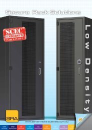
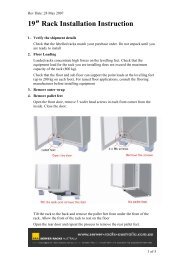
<strong>Reliability</strong> vs <strong>Redundancy</strong>100% None<strong>Reliability</strong><strong>Redundancy</strong>None100% or more
How?• How do you know what <strong>Reliability</strong> <strong>and</strong>/or<strong>Redundancy</strong> is required for your <strong>Data</strong><strong>Centre</strong>?1. Underst<strong>and</strong> the intended <strong>Data</strong> <strong>Centre</strong> use.2. Underst<strong>and</strong> stakeholder expectations.3. Underst<strong>and</strong> the reliability of the equipmentproposed.4. Underst<strong>and</strong> the <strong>Reliability</strong> of the availableenergy <strong>and</strong> water supplies.5. Underst<strong>and</strong> the available budget limitations.
How?• How do you communicate to the designengineer?• How does the designengineer communicateto you?Agree on a commonlanguage!
What are the typical issues?• Very complicated operational <strong>and</strong> servicinginter-relationships.• Poor briefing / wrong language used.• Inadequate budget to meet brief.• Downtime for repairs or maintenance.• Cheaper equipment may be less reliable <strong>and</strong>therefore require greater redundancy.• Key stakeholders on ‘different pages’.• Testing <strong>and</strong> Commissioning.• Who will operate <strong>and</strong> maintain the systems?• Underst<strong>and</strong>ing the various classifications, 999,TIA Tier 3, Uptime.
• Single Point of Failure not properlyanalysed.
• Partial or Multiple equipment failures notconsidered properly.
• Installation does not meet the design.
• Equipment is not tested or commissionedproperly.
What else can go wrong?• Complex systems difficult for techniciansto underst<strong>and</strong> <strong>and</strong> maintain.• Design makes maintenance difficult
• Routine <strong>and</strong>/or monitored equipmentmaintenance is not undertaken properly.
• End user compromises design throughpoor change management.
• End user doesn’t underst<strong>and</strong> designprinciples.
• Human Error!
How to consider <strong>Reliability</strong> <strong>and</strong><strong>Redundancy</strong>?• Mean Time To Repair (MTTR)• Mean Time To Failure (MTTF)• Mean Time Between Failure (MTBF)• Availability (MTBF / MTBF + MTTR)• MIL-STD-756B• Single Point Of Failure (SPOF)• Failure Mode Analysis (FMA)• Steady State Operation (SSO)• TIA 942 Tier system
What is the relationship betweenMTBF <strong>and</strong> <strong>Reliability</strong>?• <strong>Reliability</strong> theory is a statistical approach to predictingequipment failures.• It can become very difficult to interpret in relation to <strong>Data</strong><strong>Centre</strong> infrastructure.• Basic Theory is;• MTBF = Mean Time Between Failure• This is actually defined as the inverse of the failure rateover a given time period.• That is…failure rate (say failures per hour)λ = 1/MTBF• This then allows <strong>Reliability</strong> over a particular time periodto be estimated using an exponential equation ofR(t) = e -t/MTBF
MTBF Misconceptions• Often thought to mean a certainguaranteed time between failures.• THIS IS NOT CORRECT!• It is a calculated statistical averageassuming a constant failure rate.• MTBF does NOT account for InfantMortality (Burn in) that occurs duringfactory batch testing <strong>and</strong> specific projectcommissioning activities.
More MTBF Misconceptions• MTBF is NOT service life.• Service life is determined by specific componentusage requirements <strong>and</strong> is addressed bymonitored <strong>and</strong>/or routine maintenance orreplacement regimes.• An example of this is UPS battery replacement<strong>and</strong> generator bearing replacements.• It is important to note that in some cases MTBFcan exceed the service life of a component.
LED light fitting example• MTBF= 200,000 hours• Duration of service (t) = 8,760 hours (1yr)• Number of units = 1000• <strong>Reliability</strong> = 95.62%• Failure rate = 4.38%• Expected failures = 43
• MTBFUPS System example= 100,000 hours• Duration of service (t) = 43,800 hours(5y)• Number of units = 2• <strong>Reliability</strong> = 65%• Failure rate = 35%• Expected failures = 1
Result• It is therefore important to underst<strong>and</strong> thatit is almost certain that one UPS will failover a 5 year period.• Based on this underst<strong>and</strong>ing there mustbe an expectation that any particular itemof critical plant will fail unexpectedly atsome point in time.
What does <strong>Reliability</strong> mean?• Different things to different people!• ICT vs Power vs Cooling.• Short term power failure can result in longterm ICT failure.• Short term cooling failure may not be critical.• Can be defined as determining the risk offailure.
<strong>Redundancy</strong> requirements• Need to respond to equipment <strong>and</strong> / orsystem failures.• Depends on the specific <strong>Data</strong> <strong>Centre</strong>requirements.• Depends on the equipment installed.• Depends on the tolerable ICT downtimepermissible.• Depends on the specific system designcharacteristics.
Communicating <strong>Redundancy</strong>• We need a common language thatcommunicates redundancy• There are very few recognized st<strong>and</strong>ardsthat can be used• One that has been useful is ANCI/TIA/942• This is an American St<strong>and</strong>ard <strong>and</strong>therefore needs to be used carefully in<strong>Australia</strong>.
Overview of <strong>Data</strong> <strong>Centre</strong> CriticalSystems• ANSI/TIA 942 has an appendix thataddresses various aspects of redundancy• It exp<strong>and</strong>s on the Uptime Institute TierSystem.• The appendices cover components of a<strong>Data</strong> <strong>Centre</strong> that affect reliability <strong>and</strong>redundancy including Architectural,Structural <strong>and</strong> fire systems in addition toMechanical <strong>and</strong> Electrical.
TIA 942 – Architectural (1)Uptime TieringReferenceArchitecturalSite SelectionProximity to flood hazard asmapped on the federal floodhazard boundry or floodinsurance mapNo RequirementNot in 50 year Floodhazard areaNot within 100 year flood hazardarea <strong>and</strong> greaterthan 91m (300ft)from 50 year flood hazard areaGreater than 91m (300ft) from100 year flood hazardProximity to costal or inl<strong>and</strong> No Requirement No Requirement greater than 91m (300ft) Greater than 0.8km (1/2 mile)waterwaysProximity to major highway No Requirement No Requirement greater than 91m (300ft) Greater than 0.8km (1/2 mile)trafic arteriesProximity to major airports No Requirement No Requirement Greater than 1.6km (1 mile) <strong>and</strong>less than 48km (30 miles)Greater than 8km/5 miles <strong>and</strong>less than 48km/30 milesProximity to majormetropolitan areaParkingSeparate visitor <strong>and</strong>employee parking areasNo Requirement No Requirement less than 48km (30 miles) less than 16km (10 miles)No Requirement No Requirement yes (physically separated withseparate enteries)Separate from loading docks No Requirement No Requirement yes (physically separated withseparate enteries)Proximity of visitor parking todata centre perimiter buildingwallsTier 1 Tier 2 Tier 3No Requirement No Requirement 9.1m (30 ft) minimum separationwith physical barrier to preventvehicle from driving closerMulti-tenant occupancy No Restriction Allowed if occupanciesnon- hazardousAllowed if tenants are <strong>Data</strong>Cenntres or TelecommunicationscompaniesTier 4yes (physically separated byfence or wall with separateenteries)yes (physically separated byfence or wall with separateenteries)18.3m (60 ft) minimumseparation with physicalbarrier to prevent vehiclefrom driving closerAllowed if tenants are <strong>Data</strong>Cenntres orTelecommunications
TIA 942 – Architectural (2)Building ConstructionType of construction No Restriction No Restriction Type IIA,IIIA or VA Type 1A or 1BFire Resistive RequirementsExterior bearing walls Code requirement Code requirement 1 Hour Minimum 4 Hours MiinimumInterior bearing walls Code requirement Code requirement 1 Hour Minimum 2 Hours MinimumExterior nonbearing walls Code requirement Code requirement 1 Hour Minimum 4 Hours MiinimumStructural frame Code requirement Code requirement 1 Hour Minimum 2 Hours MinimumInterior non-computer room Code requirement Code requirement 1 Hour Minimum 1 Hour MinimumwallsInterior computer room walls Code requirement Code requirement 1 Hour Minimum 2 Hours MinimumShaft enclosures Code requirement Code requirement 1 Hour Minimum 2 Hours MinimumFloors <strong>and</strong> Floor-ceilings Code requirement Code requirement 1 Hour Minimum 2 Hours MinimumRoofs <strong>and</strong> roof-ceilings Code requirement Code requirement 1 Hour Minimum 2 Hours MinimumCompliance with NFPA 75 No Requirement Yes Yes YesMiscellanous Building ComponentsVapour barriers for computer No Requirement Yes for walls noYesYesroomrequirements for ceilingsbuilding entrances withsecurity checkpointsNo Requirement No Requirement Yes (primary building entrancemanned)Yes (primary buildingentrance manned)Access Floor Panelconstruction (when provided)No Requirement No Requirement Computer grade all steel Computer grade all steel or orcomputer grade steel withconcrete filledUnderstructure (when accessfloor is provided)No Requirement No Requirement Bolted stringer Bolted stringer with 1.2m x1.2m (4 ft x 4 ft) basket weavepatten
TIA 942 – Architectural (3)Ceilings with in Computer areas (when provided)Ceiling construction No Requirement No Requirement If provided - suspended withclean room class 10M-100Mperforated tilesSuspended with clean roomclass 100 non perforated vinylcoated gypsum board tilesCeiling Height (above raisedaccess floor if provided)2.6m (8.5 ft) minimum 2.7m (9.0 ft) minimum 3.0m (10 ft) minimum (not lessthan 460mm (18 in) above tallestpiece of equipment)3.0m (10 ft) minimum (not lessthan 600mm (24 in) abovetallest piece of equipment)RoofingClass No Restrictions Class A Class A Class AType No Restrictions No Restrictions Non-redundant with Noncombustibledeck (nomechanically attached systems)Double redundant withconcrete deck (nomechanically attachedsystems)Wind Uplift resistance Minimum coderequirementsFM I-90 FM I-90 minimum FM I-120 minimumRoof slopeDoors <strong>and</strong> WindowsFire RatingDoor SizeWindows on perimiter ofcomputer roomMinimum coderequirementsMinimum coderequirementsMinimum coderequirementsAllowed with minimumCode required fireratingMinimum coderequirements1:48 (1/4 in per foot) minimum 1:24 (1/2 in per foot) minimumMinimum codeMin Code Req, not less than 0.75 Min Code req, not less thanrequirementshour at Computer room1.5 hours at Computer RoomMinimum codeMin Code Req, not less than 1m Min Code Req, not less thanrequirementswide <strong>and</strong> 2.13m High1.2m wide <strong>and</strong> 2.13m HighAllowed with minimum interior windows allowed with interior windows allowedCode required fire rating minimum 1 hour fire rating no with minimum 1 hour fireexterior windows allowed rating no exterior windowsallowed
TIA 942 - Architectural (4)Entry LobbyPhysically Separate from No Requirement Yes Yes Yesother areas of <strong>Data</strong> <strong>Centre</strong>Fire separation from other Minimum codeMinimum codeMinimum code requirements (not Minimum code requirementsareas of <strong>Data</strong> <strong>Centre</strong>requirementsrequirementsless than 1 Hour)(not less than 2 Hour)Security Counter No Requirement No Requirement Yes Yes (physically separated)Single person interlock to No Requirement No Requirement Yes Yesprevent pass backAdminstrative OfficesPhysically Separate from No Requirement Yes Yes Yesother areas of <strong>Data</strong> <strong>Centre</strong>Fire separation from other Minimum codeMinimum codeMinimum code requirements (not Minimum code requirementsareas of <strong>Data</strong> <strong>Centre</strong>requirementsrequirementsless than 1 Hour)(not less than 2 Hour)Security Office No Requirement No Requirement Yes YesPhysically Separate from No Requirement No Requirement Yes Yesother areas of <strong>Data</strong> <strong>Centre</strong>Fire separation from other Min Code Req Min Code Req Not less than 1 Hour Not Less than 2 Hoursareas of <strong>Data</strong> <strong>Centre</strong>180 deg peepholes on No Requirement Yes Yes YesSecurity equipment <strong>and</strong>roomsDedicated <strong>and</strong> hardenedsecurity equipment <strong>and</strong>No Requirement Yes Yes, with 16mm (5/8) plywoodwalls <strong>and</strong> solid core doorYes, with 16mm (5/8) plywoodwalls <strong>and</strong> solid core doormonitoring roomsOperations <strong>Centre</strong>Operations <strong>Centre</strong> physically No Requirement No Requirement Yes YesSeparate from other areas of<strong>Data</strong> <strong>Centre</strong>Fire separation from other No Requirement No Requirement 1 Hour 2 Hoursareas of <strong>Data</strong> <strong>Centre</strong>Proximity to computer room No Requirement No Requirement Indirectly accessable (maximumof 1 adjoining room)Directly accessable
TIA 942 - Architectural (5)Restrooms <strong>and</strong> Break room areasProximity to computer room<strong>and</strong> support areasNo Requirement No Requirement If immediately adjacent,provided with leak preventionbarrierFire separation from computerroom <strong>and</strong> support areasMinimum coderequirementsMinimum coderequirementsMinimum code requirements (notless than 1 Hour)Not immediately adjacent <strong>and</strong>provided with leak preventionbarrierMinimum code requirements(not less than 2 Hour)UPS <strong>and</strong> Battery RoomsAisle widths for maintenance,repair, or equipment removalNo Requirement No Requirement Minimum code requirements (notless than 1m (3 ft) clear)Minimum code requirements(not less than 1.2m (4 ft) clear)Proximity to computer room No Requirement No Requirement Immediately adjacent Immediately adjacentFire separation from other Minimum codeMinimum codeMinimum code requirements (not Minimum code requirementsareas of <strong>Data</strong> <strong>Centre</strong>requirementsrequirementsless than 1 Hour)(not less than 2 Hour)Required Exit CorridorsFire separation from computer Minimum codeMinimum codeMinimum code requirements (not Minimum code requirementsroom <strong>and</strong> support areas requirementsrequirementsless than 1 Hour)(not less than 2 Hour)Width Min Code Req Min Code Req Minimum code requirements <strong>and</strong>not less than 1.2m (4 ft) clearShipping <strong>and</strong> Receiving areaShipping <strong>and</strong> receiving areaphysically Separate fromFire separation from otherareas of <strong>Data</strong> <strong>Centre</strong>Physical protection of wallsexposed to lifting equipmenttrafficMinimum code requirements<strong>and</strong> not less than 1.5m (5 ft)clearNo shipping <strong>and</strong>receiving area providedno Yes YesMin Code Requirement Minimum codeNot less than 1 HourNot Less than 2 Hoursif shipping <strong>and</strong>requirementsreceiving area presentNo Requirement No Requirement Yes (minimum 19mm (3/4 in) Yes (steel bollards or similarplywood wainscot)protection)Number of Loading docks No Requirement 1 per 2500sqm ofcomputer roomGenerator <strong>and</strong> Fuel Storage areasProximity to computer room<strong>and</strong> support areasProximity to publiclyaccessable areas1 per 2500sqm of computer room(2 Minimum)No Requirement No Requirement If within <strong>Data</strong> <strong>Centre</strong> Building -min 2 Hour separation from allother areas1 per 2500sqm of computerroom (2 Minimum)Separate building or exteriorweatherproof enclosures withCode required buildingseparationNo Requirement No Requirement 9m (30 ft) or greater separation 19m (60 ft) or greaterseparation
TIA 942 – Security (1)Uptime TieringReferenceSecurity Tier 1 Tier 2 Tier 3 Tier 4System CPU UPS capacity No requirement Building Building Building + 8 hourBattery minimumField Panels UPS capacity No requirement Building + 4 hourr BatteryminimumBuilding + 8 hour BatteryminimumBuilding + 24 hourBattery minimumField Device UPS capacity No requirement Building + 4 hourr BatteryminimumBuilding + 8 hour BatteryminimumBuilding + 24 hourBattery minimumDedicated Security staff pershiftNo security staffing provided 1 per 3000 sqm (1 Minimum) 1 per 2000 sqm (2 Minimum) 1 per 2000 sqm (3Minimum)No of 8 hour security shifts No requirement 1 (minimum 5 days per week) 2 (7 days per week) 3 (7 days per week)Security Access Control/Monitoring at:Generators Industrial grade lock Intrusion Detection Card Access Card AccessUPS, Telephone & MEPIndustrial grade lock Intrusion Detection Card Access Card AccessRoomsFiber Vaults Industrial grade lock Intrusion Detection Intrusion Detection Card AccessEmergency Exit Doors Industrial grade lock Monitor Delay egress per code Delay egress per codeAccessible exteriorwindows/openingsNo MonitoringIntrusion DetectionIntrusion Detection (with offsitemonitoring during shifts when nosecurity staff is present)Intrusion Detection (with offsitemonitoring during shifts whenno security staff is present)Security Operations <strong>Centre</strong> No requirement No requirement Card Access Card AccessNetwork Operations <strong>Centre</strong> No requirement No requirement Card Access Card AccessSecurity Equipment Rooms No requirement Intrusion Detection Card Access Card Access
TIA 942 – Security (2)Doors into computer rooms Industrial grade lock Intrusion Detection Card or biometric access foringressPerimiter Building doors No requirement Intrusion Detection Card access if main entrance;intrusion detection all othersMain door onto computer Industrial grade lock Card Access Single person Interlock toroom floorprevent passbackCard or biometricaccess for ingress <strong>and</strong>egressCard access if allentranceSingle person interlockto prevent passback,with biometricBullet resistant walls, windows & doorsSecurity counter in lobby No requirement No requirement Level 3 minimum Level 3 minimumSecurity counter in shipping No requirement No requirement No requirement Level 3 minimum<strong>and</strong> receivingCCTV MonitoringBuilding Perimiter <strong>and</strong>No requirement No requirement Yes YesparkingGenerators No requirement No requirement Yes YesAccess Controlled doors No requirement Yes Yes YesComputer room floors No requirement No requirement Yes YesUPS, Telephone & MEPNo requirement No requirement Yes YesRoomsCCTVCCTV recording of allNo requirement No requirement Yes - Digital Yes - Digitalactivity on all camerasRecording rate (Frames/sec) No requirement No requirement 20 frames/sec min 20 frames/sec min
TIA 942 - StructuralUptime Tiering ReferenceStructural Tier 1 Tier 2 Tier 3 Tier 4Any seismic zone acceptable, but may requireNo Restriction No Restriction No Restriction No restrictionspecial support mechanismsFacility designed to seismic zone requirements No Restriction No Restriction No Restriction In seismic zone 0, 1, 2 to Zone 3requirements, in siesmic zone 3 & 4 toZone 4 requirementsSite specific response spectra - degree of localseismic acceleratorsNo No With operation status after 10% in50 year eventWith operation status after 5% in 100year eventImportance factor I=1 I=1.5 I=1.5 I=1.5Telcommunications equipment racks/cabinetsNo Base only Fully braced Fully bracedanchored at base or supported top <strong>and</strong> bottomDeflection limitations on telcommunicationsNo No Yes Yesequipment within acceptable limitsBracing of electrical conduits <strong>and</strong> cable trays Per code Per code with importance factor Per code with importance factor Per code with importance factorBracing of mechanical system major duct runs Per code Per code with importance factor Per code with importance factor Per code with importance factorFloor loading capacity superimposed live load 7.2kPa (150lbf/sqsf) 8.4kPa (175lbf/sqft) 12kPa (250lbf/sqsf) 12kPa (250lbf/sqsf)Floor hanging capacity for ancillary loads1.2kPa (25lbf/sqsf) 1.2kPa (25lbf/sqsf) 2.4kPa (50lbf/sqsf) 2.4kPa (50lbf/sqsf)suspended from belowConcrete slab thickness at ground 127mm 127mm 127mm 127mmConcrete topping over flutes for elevated floorsaffects size of anchor which can be installed102mm 102mm 102mm 102Building LFRS (Shearwall/bracedframe/moment frame) indicates displacementof structureBuilding Energy Dissipation - PassiveDampers/base isolation (energy absorption)Battery/UPS floor vs building composition.Concrete floors more difficult to upgrade forintense loads. Steel framing with metal deck<strong>and</strong> fill much more easily upgradedSteel deck <strong>and</strong> Fill/ Pre tension concrete/ CIPMild - PT slabs much moore difficult to installanchorsSteel/Conc MF Conc.Shearwall/Steel BF Conc.Shearwall/Steel BF Conc.Shearwall/Steel BFNone None Passive dampers Passive dampers/Base isolationPT Concrete CIP Mild Concrete Steel Deck & Fill Steel Deck & fillPT Concrete CIP Mild Concrete Steel Deck & Fill Steel Deck & fill
TIA 942 – Electrical systems (1)Uptime TieringReferenceElectrical Tier 1 Tier 2 Tier 3 Tier 4GeneralStstem allowanceconcurrent maintenanceNoDown to but not including UPSOutput PanelboardsDown to but not includingPower Distribution UnitsThroughout DistributionSystemsSingle points of failurePower Syatem AnalysisComputer <strong>and</strong>TelecommunicationsEquipment Power CordsOne or more single pointsof failure fo rthedistribution systemsserving electricalequipment or mechanicalsystemsShort Circuit StudyCoordination Study ArcFalsh AnalysisSingle cord feed with100% capacityOne or more single points offailure fo rthe distributionsystems serving electricalequipment or mechanicalsystemsShort Circuit StudyCoordination Study Arc FalshAnalysisSingle cord feed with 100%capacityNo more than single points offailure for the distributionsystems serving electricalequipment or mechanicalsystemsShort Circuit StudyCoordination Study ArcFalsh Analysis Load FlowStudyRedundant cord feed with100% capacity on remainingcord or cordsNo single points of failure forthe distribution systemsserving electrical equipmentor mechanical systemsShort Circuit StudyCoordination Study ArcFalsh Analysis Load FlowStudyRedundant cord feed with100% capacity on remainingcord or cordsUtilityUtility entrance Single feed Single feed N+1 Redundant Feed 2N Redundant Feed fromdifferent utility substationsMain Utility SwitchboardService Shared Dedicated Dedicated DedicatedConstructionPanel Board with bolt oncircuit breakersSwitchboard with stationarycircuit breakersSwitchboard with drawoutcircuit breakersSwitchboard with drawoutcircuit breakersSurge Suppression Optional Optional Yes YesGenerators correctly sizedfor UPSYes Yes Yes YesUninterruptible Power Supply System
TIA 942 – Electrical systems (2)<strong>Redundancy</strong> N N N+1 2NTopologySingle or Parallel Single or Parallel ModulesModuleswith Static BypassAutomatic Bypass None Non dedicated maintenancebypass feeder to UPS outputswitchboardMaintenance BypassarrangementOutput Power DistributionBattery StringBattery TypeParallel Redundant modules,Distributed RedundantModules or Block RedundantSystemsDedicated maintenancebypass feeder to UPS outputswitchboardParallel Redundantmodules, DistributedRedundant Modules or BlockRedundant SystemsDedicated maintenancebypass feeder to UPS outputswitchboardBypass from same source Bypass from same source Bypass from same source Bypass from reserve UPSsystemPanelboard incorporating Panelboard incorporatingst<strong>and</strong>ard thermal st<strong>and</strong>ard thermal magnetic tripmagnetic trip breakersbreakersCommon string formultiple modules5 year valve regulatedlead acidDedicated string for eachmodule10 year valve regulated leadacid or flood typePanelboard incorporatingcircuit breakers that arecoordinated under overload<strong>and</strong> ground fault currentconditionDedicated string for eachmodule15 year valve regulated leadacid or flood typePanelboard incorporatingcircuit breakers that arecoordinated under allovercurrent conditionsDedicated string for eachmodule20 year lead acid flood typeBattery Minimum Backup5 minutes 7 minutes 10 minutes 15 minutesTimeBattery Monitoring System Optional Optional String level by UPS system Centralised automatedsystem to check each cellfor, voltage <strong>and</strong> impedanceor resistanceFlywheel Allowed Allowed Allowed AllowedPower Distribution UnitTransformer Optional K-rated or harmoniccancellingK-rated or harmoniccancelling, Front accessablefor maintenanceK-rated or harmoniccancelling low inrush, Frontaccessable for maintenanceAutomatic Static Transfer SwitchOvercurrent Device NA Fuse Circuit breaker Circuit breakerMaintenance Bypass NA Manual non Guided Manual Guided Manual GuidedOutput NA Single circuit breaker Dual circuit breaker Dual circuit breaker
TIA 942 – Electrical systems (3)GroundingLighting Protection System Based on Risk analysis Based on Risk analysis Yes YesService entrance groundsYes Yes Yes Yes<strong>and</strong> generator grounds fullycomply to NEC or localcodes<strong>Data</strong> <strong>Centre</strong> groundingOptional Optional Yes Yesinfrastructure in ComputerroomComputer Room Emergency Power Off (EPO) SystemInstallationDo not install if notrequired by Authoritieshaving juristrictionDo not install if not required byAuthorities having juristrictionDo not install if not requiredby Authorities havingjuristrictionDo not install if not requiredby Authorities havingjuristrictionTest Mode Optional Optional Yes YesAlarm Optional Optional Yes YesAbort Switch Optional Optional Yes YesCentral Power MonitoringMonitored Points None Utility, UPS, Generator Utility, Main Transformer,UPS, Generator, AutomaticStatic Switch, PDU,Automatic Transfer SwitchesUtility, Main Transformer,UPS, Generator, AutomaticStatic Switch, PDU,Automatic TransferSwitch,es, Surge ProtectionDevce, Critical Load BranchCircuitsNotification Method NA Control Room console Control Room console,Pager, email, Text messageControl Room console,Pager, email, Text message
TIA 942 – Electrical systems (4)Battery RoomSeparate room No Yes Yes YesIndividual battery banksNo Yes Yes Yesisolated from each otherShatterproof viewing glassNo No No Yesin Battery room doorSt<strong>and</strong>by Generating SystemsGenerator SizingSized for UPS SystemonlySized for UPS & mechanicalSystemSized for total building loadwith N+1 redundancySized for total building loadwith 2N redundancyGenerators on single bus Yes Yes Yes NoLoad BankInstallation None Provision for portable Provision for portable PermenantEquipment Tested NA Generator Generator, UPS Generator, UPSAuto Shutdown NA None Automatic upon failure ofutilityAutomatic upon failure ofutilityTestingFactory Acceptance Testing Optional Optional Yes YesSite Circuit Breaker Testing Optional Optional Contact resistance test for allcritical circuit breakers incritical <strong>and</strong> essential paths,225 Amps <strong>and</strong> higherCommissioning Optional Component level, system level Component level, systemlevel, Integrated systemPrimary injection <strong>and</strong>Contact resistance test forall critical circuit breakers incritical <strong>and</strong> essential paths,225 Amps <strong>and</strong> higherComponent level, systemlevel, Integrated system
TIA 942 - MaintenanceUptime Tiering ReferenceEquipment Maintenance Tier 1 Tier 2 Tier 3Tier 4Maintenance StaffOn site day shift Only.On call at other timesOn site day shift Only.On call at other timesOn site 24 hrs M-F, on-callweekendsOnsite 24 x 7Preventative Maintenance None None Limited preventativemaintenance programFacility Training Programs None None Comprehensive trainingprogramComprehensive preventativemaintenance programComprehensive program includingmanual operation procedures if it isnecessary to bypass control system
TIA 942 – Mechanical systems (1)Uptime Tiering ReferenceMechanicalGeneralRouting of water or drainpiping not associated with the<strong>Data</strong> <strong>Centre</strong> Equipment in datacentre spacesPositive pressure in comuterroom <strong>and</strong> associated spacesrelative to outdoors <strong>and</strong> nondata centre spacesFloor drains in computer roomfor condensate drain water,humidifers flush water <strong>and</strong>sprinkler Mechanical discharge systems water onSt<strong>and</strong>by generatorWater Cooled SystemsIndoor terminal AirConditioning unitsHumidity control for ComputerroomsElectrical Service toMechanical EquipmentTier 1 Tier 2 Tier 3 Tier 4Permitted but notrecommendedPermitted but notrecommendedNot PermittedNot permittedNo requirement Yes Yes YesYes Yes Yes YesNo requirement Yes Yes YesNo Redundant unitsOne redundant AC unit percritical areaQty of A/C units sufficent tomainain critical area during lossof one source of electrical powerQty of A/C units sufficent tomainain critical area during lossof one source of electrical powerNo requirement Humidification provided Humidification provided Humidification providedSingle path of Electricalpower to A/C equipmentSingle path of Electricalpower to A/C equipmentMultiple paths of electrical powerto AC equipment. Connected incheckerboard fashion for coolingredundancyMultiple pathsof electrical powerto AC equipment. Connected incheckerboard fashion for coolingredundancy
TIA 942 – Mechanical systems (2)Heat RejectionDry Coolers (whereapplicable)Closed- circuit fluid coolers(where applicable)Circulating pumpsPiping systemChilled Water SystemIndoor Terminal AirConditioning unitsHumidity Control for ComputerroomsElectrical Service toMechanical EquipmentHeat RejectionChilled Water Piping SystemNo redundant dry coolersNo redundant fluid coolersNo redundant condenserwater pumpsSingle path condenserwater systemNo Redundant AC unitsOne redundant unit persystemOne redundant unit persystemOne redundant unit persystemSingle path condenserwater systemOne redundant AC unit percritical areaQty of units sufficent to provideminimal temporary capacity tocritical area during loss of onesource of electrical powerQty of units sufficent to provideminimal temporary capacity tocritical area during loss of onesource of electrical powerQty of units sufficent to provideminimal temporary capacity tocritical area during loss of onesource of electrical powerHeaded parallel piped condenserwater systemQty of units sufficent to provideminimal temporary capacity tocritical area during loss of onesource of electrical powerQty of units sufficent to mainaincritical area during loss of onesource of electrical powerQty of units sufficent to mainaincritical area during loss of onesource of electrical powerQty of units sufficent to mainaincritical area during loss of onesource of electrical powerDual path condenser watersystemQty of A/C units sufficent tomainain critical area during lossof one source of electrical powerNo requirement Humidification provided Humidification provided Humidification providedSingle path of Electricalpower to A/C equipmentSingle path chilled waterpiping systemSingle path of Electricalpower to A/C equipmentSingle path chilled waterpiping systemMultiple paths of electrical powerto AC equipmentDual path ladder drop chilledwater system with isolation valvesMultiple paths of electrical powerto AC equipmentDual path chilled water systemChilled Water Pumps No Redundant units One redundant unit persystemAir-cooled Chillers No Redundant units One redundant unit persystemWater Cooled Chillers No Redundant units One redundant unit persystemCooling Towers No Redundant units One redundant unit persystemCondenser Water Pumps No Redundant units One redundant unit persystemCondenser Water PipingSystemSingle path condenserwater systemSingle path condenserwater systemQty of units sufficent to mainaincritical area during loss of onesource of electrical powerQty of units sufficent to provideminimal temporary capacity tocritical area during loss of onesource of electrical powerQty of units sufficent to provideminimal temporary capacity tocritical area during loss of onesource of electrical powerQty of units sufficent to provideminimal temporary capacity tocritical area during loss of onesource of electrical powerQty of units sufficent to provideminimal temporary capacity tocritical area during loss of onesource of electrical powerHeaded parallel piped condenserwater systemQty of units sufficent to mainaincritical area during loss of onesource of electrical powerQty of units sufficent to maintaincritical area during loss of onesource of electrical powerQty of units sufficent to maintaincritical area during loss of onesource of electrical powerQty of units sufficent to maintaincritical area during loss of onesource of electrical powerQty of units sufficent to maintaincritical area during loss of onesource of electrical powerDual path condenser watersystem
TIA 942 – Mechanical systems (3)Air-Cooled SystemsIndoor Terminal AirConditioning units/OutdoorCondensorsNo Redundant AC unitsOne redundant AC unit percritical areaQty of AC units sufficent toprovide minimal temporarycapacity to critical area duringloss of one source of electricalpowerQty of A/C units sufficent tomainain critical area during lossof one source of electrical powerElectrical Service toMechanical EquipmentHumidity control for ComputerroomsHVAC Control SystemHVAC Control SystemPower source to HVAC controlsystemPlumbing (for Water-cooledheat rejection)Make-up WaterPoints of connection tocondenser water systemSingle path of Electrical Single path of Electrical Multiple paths of electrical power Multiple paths of electrical powerpower to A/C equipment power to A/C equipmentto AC equipmentto AC equipmentNo requirement Humidification provided Humidification provided Humidification providedControl system failure willinterrupt cooling to criticalareaSingle path of Electricalpower to HVAC controlsystemControl system failure willnot interrupt cooling tocritical areaRedundant, UPS electricalpower to BMS controlControl system failure will notinterrupt cooling to critical areaRedundant, UPS electrical powerto BMS controlControl system failure will notinterrupt cooling to critical areaRedundant, UPS electrical powerto BMS controlSingle water supply with no Dual sources or one source Dual sources or one source + onsiteDual sources or one source + on-on-site storage+ on-site storagestoragesite storageSingle point of connection Single point of connection Two points of connection Two points of connection
TIA 942 – Fuel OilUptime Tiering ReferenceFuel Oil Tier 1 Tier 2 Tier 3Tier 4Bulk Storage tanks Single storage tank Single storage tanks Multiple storage tanks Multiple storage tanksStorage tanks, pumps <strong>and</strong>pipingGenerator fuel capacity at fullloadSingle pump <strong>and</strong>/orsupply pipeMultiple pumps <strong>and</strong>multiple supply pipesMultiple pumps <strong>and</strong>multiple supply pipesMultiple pumps <strong>and</strong>multiple supply pipes8 hrs 24 hrs 72 hrs 96 hrs
TIA 942 – Fire SuppressionUptime Tiering ReferenceFire Suppression Tier 1 Tier 2 Tier 3Tier 4Fire Detection System No Yes Yes YesFire Suppression SystemWhen requiredPre-action (whenrequired)Pre-Action (whenrequired)Clean agents listed inNFPAGaseous suppression system No NoEarly warning smoke detectionsystem No Yes Yes YesWater leak detection system No Yes Yes YesPre-Action (whenrequired)Clean agents listed inNFPA
TIA 942 - Items beyond the designerscontrolTHIS IS A LIST OF ITEMS BEYOND THE CONTROL OF THE DESIGNERITEM Tier 1 Tier 2 Tier 3 Tier 4SECURITYDedicated Security staff No security staffing 1 per 3000 sqm (1 1 per 2000 sqm (2 1 per 2000 sqm (3 Minimum)per shiftprovidedMinimum)Minimum)No of 8 hour security No requirement 1 (minimum 5 days 2 (7 days per week) 3 (7 days per week)shiftsper week)MAINTENANCEMaintenance StaffOnsite 24 x 7On site day shift Only.On call at other timesOn site day shift Only.On call at other timesOn site 24 hrs M-F,on-call weekendsPreventativeMaintenanceFacility TrainingProgramsNone None LimitedpreventativemaintenanceprogramNone None Comprehensivetraining programComprehensive preventativemaintenance programComprehensive programincluding manual operationprocedures if it is necessaryto bypass control system
TIA 942 - Additional items beyond designerscontrolThese items are also beyond the control of the designer as they are determined by site selection rather than data centre designITEM Tier 1 Tier 2 Tier 3 Tier 4Site SelectionProximity to flood hazard asmapped on the federal floodhazard boundry or floodinsurance mapNo Requirement Not in 50 yearFlood hazardareaNot within 100 year floodhazard area <strong>and</strong> greaterthan91m (300ft) from 50 year floodhazard areaGreater than 91m (300ft)from 100 year flood hazardProximity to costal or inl<strong>and</strong> No Requirement NowaterwaysRequirementProximity to major highway trafic No Requirement NoarteriesRequirementProximity to major airports No Requirement NoRequirementProximity to major metropolitanareaSTRUCTURALTelcommunications equipmentracks/cabinets anchored at baseor supported top <strong>and</strong> bottomNo Requirement NoRequirementgreater than 91m (300ft) Greater than 0.8km (1/2mile)greater than 91m (300ft) Greater than 0.8km (1/2mile)Greater than 1.6km (1 mile) Greater than 8km/5 miles<strong>and</strong> less than 48km (30 miles) <strong>and</strong> less than 48km/30 milesless than 48km (30 miles)less than 16km (10 miles)No Base only Fully braced Fully bracedFloor loading capacity7.2kPa8.4kPa12kPa (250lbf/sqsf)12kPa (250lbf/sqsf)superimposed live load (150lbf/sqsf) (175lbf/sqft)Concrete slab thickness at ground 127mm 127mm 127mm 127mmConcrete topping over flutes forelevated floors affects size ofanchor which can be installed102mm 102mm 102mm 102Building LFRS (Shearwall/bracedframe/moment frame) indicatesdisplacement of structureSteel/Conc MFConc.Shearwall/Steel BFConc.Shearwall/Steel BFConc.Shearwall/Steel BFBuilding Energy Dissipation -Passive Dampers/base isolation(energy absorption)None None Passive dampers Passive dampers/BaseisolationELECTRICALUtility entrance Single feed Single feed N+1 Redundant Feed 2N Redundant Feed fromdifferent utility substationsFactory Acceptance Testing Optional Optional Yes YesSite Circuit Breaker Testing Optional Optional Contact resistance test for allcritical circuit breakers incritical <strong>and</strong> essential paths, 225Amps <strong>and</strong> higherPrimary injection <strong>and</strong>Contact resistance test forall critical circuit breakersin critical <strong>and</strong> essentialpaths, 225 Amps <strong>and</strong> higher
TIA 942 - Design parameters that areaffected by capital costThese are examples where TIA makes decisions that may be over ruled by cost or practicalityITEM Tier 1 Tier 2 Tier 3 Tier 4ELECTRICALBattery Type5 year valve regulatedlead acid10 year valve regulatedlead acid or flood type15 year valve regulated leadacid or flood type20 year lead acid flood typeFactory AcceptanceTestingOptional Optional Yes YesSite Circuit BreakerTestingFUEL SYSTEMOptional Optional Contact resistance test for allcritical circuit breakers incritical <strong>and</strong> essential paths,225 Amps <strong>and</strong> higherPrimary injection <strong>and</strong> Contactresistance test for all criticalcircuit breakers in critical <strong>and</strong>essential paths, 225 Amps <strong>and</strong>higherBulk Storage tanks Single storage tank Single storage tanks Multiple storage tanks Multiple storage tanksStorage tanks, pumps Single pump <strong>and</strong>/or supply Multiple pumps <strong>and</strong> Multiple pumps <strong>and</strong> multiple Multiple pumps <strong>and</strong> multiple<strong>and</strong> pipingpipemultiple supply pipessupply pipes supply pipesGenerator fuel capacity8 hrs 24 hrs 72 hrsat full load96 hrsFIREFire SuppressionSystemWhen requiredPre-action (whenrequired) Pre-Action (when required) Pre-Action (when required)Gaseous suppressionsystem No No Clean agents listed in NFPA Clean agents listed in NFPA
TIA 942 - Non <strong>Australia</strong>n referencesThese are examples where TIA942 calls up st<strong>and</strong>ards that are not familiar to <strong>Australia</strong>n designers. In some cases it is notpossible to easily interpret these requirementsITEM Tier 1 Tier 2 Tier 3 Tier 4Building ConstructionType of construction No Restriction No Restriction Type IIA,IIIA or VA Type 1A or 1Broofing Class No Restrictions Class A Class A Class AFire Resistive RequirementsExterior bearing walls Code requirement Code requirement 1 Hour Minimum 4 Hours MiinimumInterior bearing walls Code requirement Code requirement 1 Hour Minimum 2 Hours MinimumExterior nonbearing walls Code requirement Code requirement 1 Hour Minimum 4 Hours MiinimumStructural frame Code requirement Code requirement 1 Hour Minimum 2 Hours MinimumInterior non-computer room Code requirement Code requirement 1 Hour Minimum 1 Hour MinimumwallsInterior computer room walls Code requirement Code requirement 1 Hour Minimum 2 Hours MinimumShaft enclosures Code requirement Code requirement 1 Hour Minimum 2 Hours MinimumFloors <strong>and</strong> Floor-ceilings Code requirement Code requirement 1 Hour Minimum 2 Hours MinimumRoofs <strong>and</strong> roof-ceilings Code requirement Code requirement 1 Hour Minimum 2 Hours MinimumCompliance with NFPA 75 No Requirement YesYesYesRoofingSTRUCTUREBuilding LFRS(Shearwall/bracedframe/moment frame)indicates displacement ofstructureBuilding Energy Dissipation -Passive Dampers/baseisolation (energy absorption)Conc.Shearwall/Steel BFConc.Shearwall/SteelBFConc.Shearwall/SteelBFSteel/Conc MFNone None Passive dampers Passive dampers/BaseisolationELECTRICALPower Distribution Unit -TransformerOptionalPanelboardincorporatingst<strong>and</strong>ard thermalmagnetic tripbreakersK-rated orharmoniccancellingPanelboardincorporatingst<strong>and</strong>ard thermalmagnetic tripbreakersK-rated or harmoniccancelling, Frontaccessable formaintenancePanelboardincorporating circuitbreakers that arecoordinated underoverload <strong>and</strong> groundfault current conditionK-rated or harmoniccancelling low inrush,Front accessable formaintenancePanelboardincorporating circuitbreakers that arecoordinated under allovercurrent conditionsUPS Output Power Distribution
TIA 942 - Common design deficiencies (1)THE FOLLOWING LIST OF ITEMS FROM TIA REPRESENT AREAS WHERE DESIGNS ARE OFTEN DEFICIENTITEM Tier 1 Tier 2 Tier 3 Tier 4Ststem allowanceconcurrent maintenanceNoDown to but notincluding UPS OutputPanelboardsDown to but notincluding PowerDistribution UnitsThroughout DistributionSystemsSingle points of failurePower Syatem AnalysisConstructionOne or more single pointsof failure fo rthedistribution systemsserving electricalequipment or mechanicalShort Circuit StudyCoordination Study ArcFalsh AnalysisPanel Board with bolt oncircuit breakersOne or more singlepoints of failure fo rthedistribution systemsserving electricalequipment orShort Circuit StudyCoordination Study ArcFalsh AnalysisSwitchboard withstationary circuitbreakersNo more than singlepoints of failure for thedistribution systemsserving electricalequipment orShort Circuit StudyCoordination StudyArc Falsh AnalysisLoad Flow StudySwitchboard withdrawout circuitbreakersGroundingLighting Protection System Based on Risk analysis Based on Risk analysis Yes YesService entrance groundsYes Yes Yes Yes<strong>and</strong> generator grounds fullycomply to NEC or localcodes<strong>Data</strong> <strong>Centre</strong> groundingOptional Optional Yes Yesinfrastructure in ComputerroomComputer Room EmergencyPower Off (EPO) SystemDo not install if notrequired by Authoritieshaving juristrictionDo not install if notrequired by Authoritieshaving juristrictionDo not install if notrequired by Authoritieshaving juristrictionNo single points of failurefo rthe distribution systemsserving electricalequipment or mechanicalsystemsShort Circuit StudyCoordination Study ArcFalsh Analysis Load FlowStudySwitchboard with drawoutcircuit breakersDo not install if notrequired by Authoritieshaving juristrictionInstallationTest Mode Optional Optional Yes YesAlarm Optional Optional Yes YesAbort Switch Optional Optional Yes YesElectrical Service toMechanical EquipmentSingle path of Electricalpower to A/C equipmentSingle path of Electricalpower to A/C equipmentMultiple paths ofelectrical power to ACequipment. Connectedin checkerboardfashion for coolingredundancyMultiple pathsof electricalpower to AC equipment.Connected incheckerboard fashion forcooling redundancy
TIA 942 - Common design deficiencies (2)HVAC Control SystemHVAC Control SystemControl system failure willinterrupt cooling tocritical areaControl system failurewill not interrupt coolingto critical areaControl system failurewill not interruptcooling to critical areaControl system failure willnot interrupt cooling tocritical areaPower source to HVACcontrol systemSingle path of Electricalpower to HVAC controlsystemPlumbing (for Water-cooled heat rejection)Make-up WaterSingle water supply withno on-site storagePoints of connection tocondenser water systemMAINTENANCEMaintenance StaffSingle point of connectionRedundant, UPSelectrical power to BMScontrolDual sources or onesource + on-site storageSingle point ofconnectionRedundant, UPSelectrical power toBMS controlDual sources or onesource + on-sitestorageTwo points ofconnectionOn site day shift Only. Oncall at other timesOn site day shift Only.On call at other timesOn site 24 hrs M-F, oncallweekendsPreventative Maintenance None None Limited preventativemaintenance programFacility Training Programs None None Comprehensivetraining programRedundant, UPS electricalpower to BMS controlDual sources or onesource + on-site storageTwo points of connectionOnsite 24 x 7Comprehensivepreventative maintenanceprogramComprehensive programincluding manualoperation procedures if itis necessary to bypasscontrol system
Summary (design)• Establish clear <strong>and</strong> concise redundancyrequirements.• Use a language understood by all parties.• Get a clear underst<strong>and</strong>ing of allstakeholder expectations including thebudget <strong>and</strong> all risks.• Design to meet the brief within the budget.• Ensure designers underst<strong>and</strong> the intendedmaintenance regime.
Summary (operation)• Install, commission <strong>and</strong> operate inaccordance with the design.• Establish a regular failure mode testingregime.• Undertake both monitored <strong>and</strong> properroutine maintenance.• Ensure the end users underst<strong>and</strong> thespecific design principles.• Ensure the <strong>Data</strong> <strong>Centre</strong> has an effectivechange management process.
Questions