HOT GLASS VACUUM PRESS INSTRUCTION MANUAL - Hot Press
HOT GLASS VACUUM PRESS INSTRUCTION MANUAL - Hot Press
HOT GLASS VACUUM PRESS INSTRUCTION MANUAL - Hot Press
You also want an ePaper? Increase the reach of your titles
YUMPU automatically turns print PDFs into web optimized ePapers that Google loves.
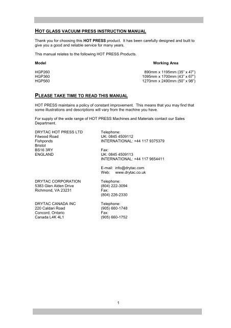
<strong>HOT</strong> <strong>GLASS</strong> <strong>VACUUM</strong> <strong>PRESS</strong> <strong>INSTRUCTION</strong> <strong>MANUAL</strong>Thank you for choosing this <strong>HOT</strong> <strong>PRESS</strong> product. It has been carefully designed and built togive you a good and reliable service for many years.This manual relates to the following <strong>HOT</strong> <strong>PRESS</strong> Products.ModelWorking AreaHGP260 890mm x 1195mm (35” x 47”)HGP360 1095mm x 1700mm (43” x 67”)HGP560 1270mm x 2490mm (50” x 98”)PLEASE TAKE TIME TO READ THIS <strong>MANUAL</strong><strong>HOT</strong> <strong>PRESS</strong> maintains a policy of constant improvement. This means that you may find thatsome illustrations and descriptions will vary from the machine you have.For supply of the wide range of <strong>HOT</strong> <strong>PRESS</strong> Machines and Materials contact our SalesDepartment.DRYTAC <strong>HOT</strong> <strong>PRESS</strong> LTD Telephone:Filwood Road UK: 0845 4509112Fishponds INTERNATIONAL: +44 117 9375379BristolBS16 3RYFax:ENGLAND UK: 0845 4509113INTERNATIONAL: +44 117 9654411E-mail: info@drytac.comWeb: www.drytac.co.ukDRYTAC CORPORATIONTelephone:5383 Glen Alden Drive (804) 222-3094Richmond, VA 23231Fax:(804) 226-2330DRYTAC CANADA INCTelephone:220 Caldari Road (905) 660-1748Concord, OntarioFax:Canada L4K 4L1 (905) 660-17521
SETTING-UP YOUR NEW <strong>VACUUM</strong> <strong>PRESS</strong>During manufacture, each Vacuum <strong>Press</strong> is set up and tested thoroughly.Your press and its pump are each packed in a carefully designed carton. These have beentested to ensure that the items are in perfect condition upon arrival.Please check the carton and the press carefully. If there are any obvious signs of damage,contact your dealer.Prepare a BenchPlease ensure that you have a suitable stand, bench or table ready. This should be firm and flat,and of an adequate size and strength. Ideally, it should be at least twice the size of the press.That way, you will have an adequate space for preparation of the work you will be mounting andlaminating. We supply a range of tailor made stands offering a firm and sturdy support for ourrange of vacuum presses.Lift the press onto the stand or bench and temporarily position it so that you can gain access tothe connection points at the rear of the machine.The ideal working height of the press will vary depending on the height of the operator.Experience indicates that a table top height of between 700mm (28”) and 790mm (31”) will besuitable.Open your <strong>Press</strong>Now, open your press. The top should stay in the open position supported by the gas struts.Open and close the top a few times to ensure that the struts are functioning properly.Open the Pump BoxThe pump should be placed on or near the floor. Vibration during operation may cause the pumpto move and could cause damage if the pump fell from a table.Connecting the Vacuum PumpConnect the piece of vacuum tubing. The vacuum tubes are a simple “push fit” into the specialconnectors. You will feel two stages of resistance as the tube is fitted. The ends of the tubemust be clean and smooth to ensure a good seal. If damaged, simply cut off 5mm (1/4”) with asharp knife.3
Connect one end of the tube to the fitting on the rear of the press.Connect the other end of the tube to the fitting on the pump.Should you need to remove a tube from a connector, simply push down on the rim of the fittingwith a finger and the tube should easily pull out.The electrical lead from the pump can now be connected to the socket in the rear of the press.4
Connect to the electrical outletExamine the plate carrying the serial number and voltage. Check that the voltage is suitable foryour local supply. It is important that a supply of the right amperage is used. The table belowshould help you select the correct supply and connectors.Model Current(A) Power(kW) Size of supply (A)HGP260 11 2.5 13HGP360 18 4.2 20HGP560 25 6.7 30Depending on the market your machine was built for, the wiring will be coloured as follows:BROWN = LIVEBLUE = NEUTRALGREEN/YELLOW = EARTHor,BLACK = LIVEWHITE = NEUTRALGREEN = GROUNDFor operator safety, it is essential that the machine be correctly earthed (grounded).After connecting the vacuum tube and the pump connect the mains lead to the outlet, but do notswitch on yet. When facing the back of the press check that the two circuit breakers are in the“ON” position i.e., the switches are pointing to the right. The one nearest the centre of themachine protects you from electric shock should a wire become loose. You should test itperiodically by using the small button marked “T”. The second circuit breaker prevents overloadshould a short circuit occur. Now slide the press into the required working position on the worktop.5
ControlsExamine the control panel on the front of the press.Control Panel Layout1 2 3 4 5 6Key Controls are:1. Variable <strong>Press</strong>ure Adjustment - Allows pressure adjustment (by regulating thevacuum) for mounting onto foam centred board.2. Vacuum gauge - Indicates actual vacuum pressure. A satisfactorymaximum reading is 25”+.3. Auto/Manual Switch - Acts as a simple on/off switch for the pump if you do notneed to use the timer.4.Timer- Automatically controls the vacuum pump andwill switch it off at the end of the pre-set cycle.5. Power Switch - Switches on the power supply to the press.6. Temperature Controller - indicates the actual glass temperature, andmaintains that temperature at your chosen presetlevel.Now Switch OnCheck that the pump switch on the front panel is in the AUTO position.Switch on the power switch on the front of the press. The digital display on the temperaturecontroller will initially show the letters “LAE”, followed a couple of seconds later by a nominaltemperature. It will soon start to rise, and after about 15 minutes will show the temperature presetduring manufacture. This will normally be 90 O C or 195 O F.6
Adjustment of Temperature Controller1 2 3 4To change the set temperature, press and hold Button 1, now press Button 2 to lower settemperature or button 3 to raise set temperature. To turn heating off, press and hold button 4 forthree seconds. To turn heating on again, press button 4 for three seconds.When the press is heating, the “out1” indicator will illuminate.At the factory the temperature controller is set to allow a maximum temperature of 115 O C or 239O F, depending on which market your machine was made for.Operating the vacuum pumpAutomatic Control1 2 3 4For automatic control, the pump switch should be set in the AUTO Position. The timer controlsthe length of the cycle. To start the cycle, press button 1. Once the pre-set time has elapsed thepump will stop, air will be let back into the press and the counter will return to showing the pre-settime.If you wish to stop the cycle part way through simply press button 1. This will stop the pump,release the vacuum and reset the timer.To Change The Pre-set Timer<strong>Press</strong> button 2 to reduce the time or button 3 to increase the time.7
Manual OperationSwitching the PUMP switch to the <strong>MANUAL</strong> position will cause the pump to start. The pump isstopped when the switch is returned to the AUTO position.The timer also has a manual mode which allows it to be used as a simple on/off switch. <strong>Press</strong>button 4 and hold for five seconds. The display will change to “OFF”. <strong>Press</strong>ing button 3 will turnthe pump on and button 2 will stop it. To revert back to timed operation, press button 4 again forfive seconds, the display will revert to the time. Although this facility is available we advise usersto carry out manual operation using the AUTO/<strong>MANUAL</strong> switch rather than the manual mode onthe timer.Safety noteThis product should only be used for the purpose and manner for which it was designed. Weinclude care and maintenance advice with our product that should be read carefully and followedbefore use.For complete operator safety, Vacuum <strong>Press</strong> machines are fitted with circuit breakers, fuses anda high temperature overriding cut-out.The high temperature cut-out can be seen attached to the inside of the glass. If the temperaturerises above 125 o C/ 257 o F, the cut-out will turn off all power to the system. It will thenautomatically reset itself after the press has cooled sufficiently, which may take up to 15 minutes.If the cut-out operates repeatedly, please contact your dealer.ROTINE MAINTENANCE OF <strong>PRESS</strong>CleaningSweep or vacuum dust and bits from the rubber diaphragm. Keeping dirt away from the machinewill help prevent the pump becoming blocked.Check the pump filter bowl for water periodically. To drain the bowl, ensure the pump is switchedoff, then simply unscrew the bowl, tip the water out and re-fit the bowl.Clean all the way around the grey silicone seal with a damp cloth, checking for foreign matterand cuts.If any adhesive has accumulated on the glass, this may be dissolved with acetone or nail varnishremover DO NOT USE ABRASIVE CLEANERS.The coloured metal frame may be cleaned with normal, non-abrasive household cleaners.SOME COMMON PROBLEMS1. Foam trapped in the sealIt is very easy for the foam sheet to become misplaced, and inadvertently be trapped in the seal.This allows air to flow in, preventing a good vacuum being pulled. Foam used in the press willtend to expand in size over time. As this happens, you should lay it on the bench and slice astrip off each edge.8
2. Very small gap at the rear of pressThis can be created by movement whilst the press is in transit, follow the instructions foradjusting the hinges.3. Very small gap at front of pressThe catches may need adjustment.4. Vacuum problemsFirst try the “Thumb Test”. Put your thumb over the extractor and observe the gauge.Not a good Vacuum ? - Check the following:1. Check that the tube fittings are tight.2. Check the filter for blockage. Ensure the pump is off, then unscrew the filterbowl, pull the filter cartridge out and refit the bowl. If this rectifies the fault, the filter element willneed cleaning. Unscrew the retaining plate at the bottom of the cartridge and withdraw the filterelement, wash in ordinary household detergent and re-assemble complete unit.3. Check the pump. If it is faulty, speak to your dealer.If there are still problems - check the following:1. Is there anything trapped in the seal, is it damaged? Any paper, foam orcanvas blocking the seal can cause a vacuum leak. If the seal is damaged, remove a sectionand replace.2. Check the press is level. If one edge is overhanging a table, it can prevent agood seal.3. Are the catches tight enough? The catches should close with a smooth“click”. Over tightening will make the machine difficult to close and will not improve the vacuum.4. Try to adjust the hinges. Follow the guide on page 13 to adjust the bottomhinges.9
5. The “bookmark” test. Cut thin strips of paper and place in different sections ofthe seal around the press. Close the lid and secure the catches, then try to remove the paper.The paper will normally be held tight. If the paper can be pulled out, this will indicate a gapbetween the seal and the lid of the press.6. Search for a hole in the diaphragm. Splits are most common along the edgesand corners. Switch off power supply to press. Remove the screws holding the diaphragm.Then lift it out of the press and inspect both sides for holes.Vacuum will not release?Does the solenoid (the Solenoid can be found at the rear of the <strong>Press</strong>ure Adjuster) click whenyou switch on? If not this indicates that the solenoid is faulty.CatchesThe catches at the front should close with a comfortable “click”. If they are loose, or if they needexcessive pressure to close, they can readily be adjusted by turning the catch on the pivotedthreaded shaft. Do this just one turn at a time.10
Lengthening the amount of threaded shaft visible (by turning anti-clockwise) will have the effectof tightening the catch, and shortening the amount (by turning clockwise) will have the effect ofloosening it.The catch is designed to work with a light “click”. Adjusting it to make it excessively tight will notimprove the effectiveness of the vacuum seal, and may seriously damage the catch.11
HingesThe hinges at the rear of the press are designed and fitted in such a way that they can be easilyadjusted to ensure a good vacuum seal. Ensure that both hinges are adjusted by the sameamount to keep the press lid level.The top part of the hinge is bolted to the top frame, and cannot be moved.Adjustment is carried out on the bottom part of the hinge. Both bolts pass through elongatedholes in the frame. Should it become apparent that the grey sealing gasket is not in contact withthe underside of the platen all the way across the back of the press, then the adjustmentprocedure is as follows:Bolts ABolt BClose the <strong>Press</strong>, loosen both bolts A 1 / 2 a turn. Switch on vacuum pump.Using a spanner lightly screw up bolt B on each hinge a little at a time until a vacuum is pulled.Only a small adjustment will be required. Re-tighten both bolts A.Checking & changing fusesThe fuses are located on the left side of the press. Disconnect from the mains. Open the fuseholder using a screwdriver, replace with a fuse of the same rating. Spare fuses are locatedunder the rubber diaphragm.Bolt ABolt BBolt Bolt B A12
WEEE RegulationsThis equipment falls within the scope of the European Union WasteElectrical and Electronic Equipment. At the end of it’s useful life, it mustbe disposed of in accordance with local codes in order to facilitaterecycling.13


