pro-wing installation instructions - Mill Supply, Inc.
pro-wing installation instructions - Mill Supply, Inc.
pro-wing installation instructions - Mill Supply, Inc.

You also want an ePaper? Increase the reach of your titles
YUMPU automatically turns print PDFs into web optimized ePapers that Google loves.
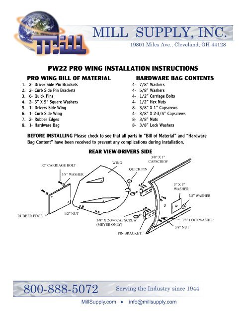
MILL SUPPLY, INC.19801 Miles Ave., Cleveland, OH 44128PW22 PRO WING INSTALLATION INSTRUCTIONSPRO WING BILL OF MATERIAL1. 2- Driver Side Pin Brackets2. 2- Curb Side Pin Brackets3. 6- Quick Pins4. 2- 5” X 5” Square Washers5. 1- Drivers Side Wing6. 1- Curb Side Wing7. 2- Rubber Edges8. 1- Hardware BagHARDWARE BAG CONTENTS4- 7/8” Washers4- 5/8” Washers4- 1/2” Carriage Bolts4- 1/2” Hex Nuts8- 3/8” X 1” Capscrews4- 3/8” X 2-3/4” Capscrews8- 3/8” Nuts8- 3/8” Lock WashersBEFORE INSTALLING Please check to see that all parts in “Bill of Material” and “HardwareBag Content” have been received to prevent any complications during <strong>installation</strong>.1/2” CARRIAGE BOLT5/8” WASHERREAR VIEW-DRIVERS SIDEWINGQUICK PIN3/8” X 1”CAPSCREW5” X 5”WASHER7/8” WASHERRUBBER EDGE1/2” NUT3/8” X 2-3/4”CAP SCREW(MEYER ONLY)3/8” LOCKWASHER3/8” NUTPIN BRACKET800-888-5072Serving the Industry since 1944<strong>Mill</strong><strong>Supply</strong>.com ♦ info@millsupply.com
WARNING DISCLAIMER1. Remove Pro-Wing attachments before traveling on public streets, as plow blade may be over legal size with<strong>wing</strong>s attached.2. Pro-Wings will not withstand the same degree of abuse as the blade. AVOID HITTING SOLID OBJECTS. Plowwith care.3. Pro Wing attachments add additional weight to your plow blade. The lifting ability of your power unit may bediminished and premature failure of your power unit may occur.LIMITED WARRANTYMaterials and workmanship for a period of 180 days, from date of customer (user) purchase.WARRANTY EXCLUSIONSIn no event shall Buyers Products Company (Pro-Wing Attachments) be liable for incidental or consequenstialdamages, or for damages resulting from mis-use, abuse, acts of God, or alterations of this <strong>pro</strong>duct. Damagesof failures of any <strong>pro</strong>ducts is attached. Limitations subject to individual state laws.PRO-WING INSTALLATION INSTRUCTIONS***READ ALL INSTRUCTIONS PRIOR TO INSTALLATION***1. Pro-Wings are not recommended for Meyer 2-Meter plows, Western 8-1/2 foot plows or any brand 9 or 10 foot plowsexcept the Meyer 9 foot plow.2. A new or near-new steel, end punched cutting edge should be used before applying Pro-Wings3. Park truck on a flat level surface, and lower plow blade.4. Drill or torch-cut a 1-1/8 inch diameter hole through the plow blade at the location shown in figure #1***Be sure to follow the contour of the blade***5. Assemble drivers side (left hand) pin brackets onto the plow blade using C-clamps as shown in figure #2. Place Wingonto plow and pin brackets using quick pins to hold in place. Make sure the <strong>wing</strong> will pivot freely in and out of the1-1/8” hole while resting on the pin brackets.6. Remove <strong>wing</strong> and mark the location of the pin brackets on the plow blade. If bolting the pin brackets to the blade,mark hole positions in the slots of the pin brackets. Be sure to avoid vertical ribs (except for Meyer plows). Set punchhole locations and drill 3/8 inch holes in plow blade. If welding pin brackets to plow blade, tack weld first and recheckto see that <strong>wing</strong> still pivots through the 1-1/8” hole (step 5). Weld fast.7. With pin brackets now installed, place Pro-Wing onto the pin brackets and rotate the <strong>wing</strong> pin through the plow bladehole. Use 7/8” flat washers on top of the 5” x 5” square washer to take up play. (Figures #2 and #4)8. If the A-Frame is not attached to the truck, raise the rear of the A-Frame 10” inches off the ground. Place rubbercutting edge tightly against the ground and the plows steel edge. (Figure #5) Mark the rubber edge with chalk fromthe rear of the <strong>wing</strong>. Drill two 3/4” holes according to your reference marks. Remove Wing from plow and bolt rubberedge to the <strong>wing</strong> using the carriage bolts and 5/8” flat washers as shown in figure #5.9. Blade guides can be bolted on when desired. (Figure #5)10. Repeat steps 4 through 8 for passenger side (right hand) Wing.
FIGURE 1FIGURE 24 1/2”3/8” HOLES1-1/8” HOLE1-1/8 inch diameter hole9-5/8” FOLLOWCONTOUROF BLADEBRACKETSPINFRONT VIEW DRIVERS SIDEREAR VIEW DRIVERS SIDEFIGURE 3FIGURE 4LONG BOLT FOR MEYER( 2 PLACES )QUICK PINSHORT BOLTPLOW BLADEWINGDRIVER SIDE WING5” X 5” WASHER7/8” WASHERFRONT VIEW DRIVERS SIDELOCK WASHERWING PIN BRACKETHEX NUTREAR VIEW DRIVERS SIDEFIGURE 5DRILL TWO 5/16” HOLESTO MOUNT BLADE GUIDESPLOW BLADEWINGRUBBER EDGEFRONT VIEW DRIVERS SIDE1/2” CARRIAGE BOLT ASSY.5/8”F.W.