

TTS Golf RoToR oWNERS MANUAl - Hunter Industries
TTS Golf RoToR oWNERS MANUAl - Hunter Industries
TTS Golf RoToR oWNERS MANUAl - Hunter Industries

Create successful ePaper yourself
Turn your PDF publications into a flip-book with our unique Google optimized e-Paper software.
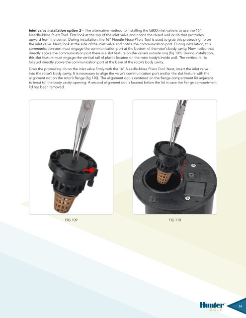
Inlet valve installation option 2 – The alternative method to installing the G800 inlet valve is to use the 16”Needle-Nose Pliers Tool. First look at the top of the inlet valve and notice the raised wall or rib that protrudesupward from the center. During installation, the 16” Needle-Nose Pliers Tool is used to grab this protruding rib onthe inlet valve. Next, look at the side of the inlet valve and notice the communication port. During installation, thiscommunication port must engage the communication port at the bottom of the rotor’s body cavity. Now notice thatdirectly above the communication port there is a slot feature on the valve’s outside ring (fig 109). During installation,this slot feature must engage the vertical rail of plastic located on the rotor body’s inside wall. The vertical rail islocated directly above the communication port at the base of the rotor’s body cavity.Grab the protruding rib on the inlet valve firmly with the 16” Needle-Nose Pliers Tool. Next, insert the inlet valveinto the rotor’s body cavity. It is necessary to align the valve’s communication port and/or the slot feature with thealignment dot on the rotor’s flange (fig 110). The alignment dot is centered on the flange compartment lid adjacentto (next to) the body cavity opening. A second alignment dot is located below the lid in case the flange compartmentlid has been removed.Fig 109 Fig 110Fig 108 Fig 108 Fig 109 Fig 10936


