4 Channel DC motor Controller Manual - Robot Gear Australia
4 Channel DC motor Controller Manual - Robot Gear Australia
4 Channel DC motor Controller Manual - Robot Gear Australia

You also want an ePaper? Increase the reach of your titles
YUMPU automatically turns print PDFs into web optimized ePapers that Google loves.
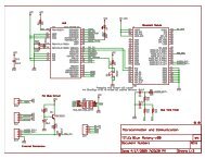
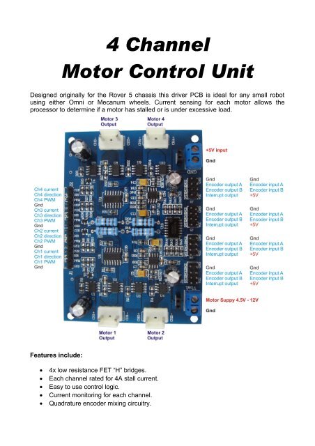
4 <strong>Channel</strong>Motor Control UnitDesigned originally for the Rover 5 chassis this driver PCB is ideal for any small robotusing either Omni or Mecanum wheels. Current sensing for each <strong>motor</strong> allows theprocessor to determine if a <strong>motor</strong> has stalled or is under excessive load.Features include:• 4x low resistance FET “H” bridges.• Each channel rated for 4A stall current.• Easy to use control logic.• Current monitoring for each channel.• Quadrature encoder mixing circuitry.
Power connectors:The PCB has two power connectors. One is +5V for logic (Vcc) and one for the <strong>motor</strong>power supply. The <strong>motor</strong> power supply should not be connected without firstconnecting the +5V for logic. This device is rated for a maximum <strong>motor</strong> supply voltageof 12V. Exceeding this voltage may permanently damage the device.The encoder mixing circuit:Unlike most <strong>motor</strong> controllers this PCB includes 4 mixing circuits for use with up to 4quadrature encoders. The mixing circuit takes the 2 inputs from a quadrature encoderand mixes them into a single output. Note that the interrupt output changes state wheneither input changes.This allows a single interrupt pin to monitor both inputs of a quadrature encoder.Because the interrupt output is twice the frequency of either input it also allows speedand distance to be measured with twice the resolution.Current output:Each channel has a current sensing circuit. The output of this circuit is approximately1V for each amp the <strong>motor</strong> draws (5V maximum). This output can be connecteddirectly to the analog input of any 5V micro controller.Control logic:The built in control logic allows each <strong>motor</strong> to be controlled by 2 pins. Driving thedirection pin high or low will cause the <strong>motor</strong> to run forward or reverse. The PWM pinis used to control the <strong>motor</strong> speed. When this pin is low, the <strong>motor</strong> is off. When this pinis high the <strong>motor</strong> is at full power. To vary the speed of the <strong>motor</strong> this pin must be PulseWidth Modulated.Motor output:Each channel has a <strong>motor</strong> output socket. Connect any 4.5V –12V <strong>DC</strong> <strong>motor</strong> with a stallcurrent of less than 4.5A to these pins. Exceeding 4.5A on these pins may permanentlydamage this device.