general recommendations - safety - AJ Maskin AS
general recommendations - safety - AJ Maskin AS
general recommendations - safety - AJ Maskin AS

Create successful ePaper yourself
Turn your PDF publications into a flip-book with our unique Google optimized e-Paper software.
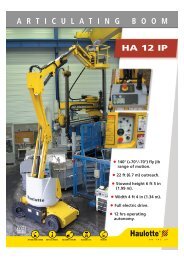
REPAIR MANUALSELF-PROPELLED SCISSOR PLATFORM242 031 8680 - E 05.05 GBISO 9001ARTICULEESMATSTELESCOPIQUESCISEAUXTRACTEESL'ACCES A L'ESPACEPINGUELY HAULOTTE • LA PERONNIERE - BP 9 - 42152 L'HORME • Tél. +33 (0) 4 77 29 24 24 • Fax SAV +33 (0) 4 77 31 28 11email haulotte@haulotte.com • Web www.haulotte.com
Repair manual 1GENERALThis manual gives the information required for you to perform servicing and repairoperations on certain pieces of equipment yourself.However, we would like to bring your attention to the importance of:• respecting the <strong>safety</strong> instructions concerning the machine itself, its use andits environment,• use within the limits of its performance,• correct servicing to ensure long service life.During and after the guarantee period, our After-Sales service is available toperform any servicing operations you may require.In this case, contact our local agency or our Plant After-Sales service, specifyingthe exact type of machine and its serial number.To order consumables or spare parts, use the "Instructions for use andmaintenace" manual and the "Spare parts" catalogue to order original parts, theonly guarantee of interchangability and perfect operation.REMINDER:We would like to remind you that our machines comply with theclauses of the "Machines Directive", 89/392/CEE, dated June 14th1989, modified by directives 91/368/CEE, dated June 21st 1991, 93/44/CEE, dated June 14th 1993, 93/68/CEE (98/37/CE) dated July22nd 1993 and 89/336 CEE, dated May 3rd 1989; to directive 2000/14/CE and directive EMC/89/336/CE.Caution!The technical data in thismanual is not binding and wereserve the right to makeimprovements ormodifications without alteringthis manual.1
21 Repair manual
Repair Manual4.4 - END OF TRAVEL SWITCHES CHART .....................................................................254.5 - SERIAL CARD ...........................................................................................................254.6 - MDI.............................................................................................................................264.7 - USING THE ON-BOARD CHARGER ........................................................................274.8 - CHOPPER .................................................................................................................285 - HYDRAULIC DIAGRAM.............................................................................................295.1 - HYDRAULIC DIAGRAM FOR OPTIMUM 6 AND 8 (B16288B) MODEL....................295.2 - HYDRAULIC INSTALLATION DIAGRAM A14681D ..................................................306 - DESCRIPTION OF THE HYDRAULIC CIRCUIT........................................................336.1 - HYDRAULIC BLOCK’S COMPONENTS ...................................................................336.2 - MK4 HYDRAULIC BLOCK SPECIFICATIONS..........................................................356.3 - HYDRAULIC FUNCTIONING ....................................................................................397 - MAINTENANCE..........................................................................................................457.1 - GENERAL RECOMMENDATIONS............................................................................457.2 - MAINTENANCE DEVICE...........................................................................................457.3 - ELECTRICITY SUPPLY.............................................................................................467.4 - MAINTENANCE PLAN...............................................................................................467.5 - OPERATIONS............................................................................................................487.6 - PRESENCE OF LABELS...........................................................................................497.7 - PRESENCE OF MANUALS .......................................................................................498 - PREVENTIVE MAINTENANCE SHEETS ..................................................................519 - OPERATING INCIDENTS ..........................................................................................619.1 - TABLE OF INCIDENTS .............................................................................................619.2 - FAILURE DETECTION FLOW CHARTS ...................................................................67ii
Repair Manual10 - CORRECTIVE MAINTENANCE PROCEDURES .................................................... 105iii
ivRepair Manual
Repair manual 31 - GENERAL RECOMMENDATIONS - SAFETY1.1 - GENERAL WARNING1.1.1 - ManualThis manual aims to help maintenance personnel service and repair the machine.It cannot, however, replace the basic training required by any person working onthe site equipment.The site manager must inform operators of the <strong>recommendations</strong> in theinstruction manual. He is also responsible for application of current "userregulations" in the country of use.Before operating on the machine, it is essential to be familiar with all the<strong>recommendations</strong> in this manual and the user manual to ensure personnel andequipment <strong>safety</strong>.1.1.2 - LabelsPotential dangers and <strong>recommendations</strong> for the machine are indicated on labelsand plates. Read the instructions on them.All labels conform to the following colour code:• Red indicates a potentially fatal danger.• Orange indicates a danger that may cause serious injury.• Yellow indicates a danger that may cause material damage or slight injury.Maintenance pesrsonnel must ensure that these labels and plates are in goodconditions and keep them legible. Spare labels and plates can be supplied by themanufacturer on request.1.1.3 - SafetyEnsure that any person entrusted with the machine is take the <strong>safety</strong> measuresimplied by its use.Avoid any working mode that may affect <strong>safety</strong>. Any use that does not comply withthe <strong>recommendations</strong> may generate risks and damage to people and equipment.After intervention, maintenance personnel must check that the operator manualis present. This must be kept by the user throughout the machine’s service life,even if it is loaned, rented or sold.Ensure that all the plates or labels related to <strong>safety</strong> and danger are complete andlegible.Caution!To attract the reader’sattention, instructions areindicated by thisstandardised sign.5
3 Repair manual1.2 - GENERAL SAFETY RECOMMENDATIONS1.2.1 - OperatorsOperators must be aged 18 or over and hold an operating permit issued by theemployer after verification of medical aptitude and the practical platform operationtest.Caution!Only trained operators mayuse Haulotte self-propelledplatforms.There must be at least two operators present, so that one of them can:• intervene rapidly if necessary,• take over the controls in the case of accident or breakdown,• monitor and prevent machines or people from circulating around the platform,• guide the platform operator if necessary.1.2.2 - EnvironmentNever use the machine:• On soft, unstable or cluttered floors.• On a floor with a tilt greater than the allowed limit.• With a windspeed above the permitted level. In case of outdoor use, checkthat windspeed is lower or equal to the permitted level using an anemometer.• Near electric lines (find out about minimum distances according to current).In temperatures of less than -15°C (in particular, in cold rooms); consult ourservice department if work is required in conditions below -15°C.• In an explosive atmosphere.• In an incorrectly ventilated area, as exhaust fumes are toxic.• During storms (risk of being struck by lightning).• At night if the machine is not equipped with an optional light.• In the presence of intense electromagnetic fields (radar, mobile and highcurrent).DO NOT DRIVE ON THE PUBLIC HIGHWAY.1.2.3 - Using the machineIt is important to ensure that in normal use, i.e. platform operation, the platformstation selection key remains in the the platform position to enable control of themachine from the platform. If a problem occurs on the platform, a person presentand trained in emergency/standby manoeuvres can help by putting the key in theground control position.Never use the machine with:• a load greater than the nominal load,• more people than the authorised number,• lateral force in the platform greater than the level permitted,• wind speed higher than the permitted level.6
Repair manual 3To avoid all risk of serious fall, operators must respect the following instructions:• Hold the hand rails firmly when climbing onto or operating the platform.• Wipe any traces of oil or grease off the steps, floor and hand rails.• Wear protective clothing suited to working conditions and current local legislation,in particular when working in hazardous areas.• Do not disable the <strong>safety</strong> system end of stroke contactors.• Avoid contact with fixed or mobile obstacles.• Do not increase working height by using ladders or other accessories.• Never use the hand rails as a means of access for getting onto and off theplatform (use the steps provided on the machine).• Never climb on the hand rails when the platform is raised.• Never drive the platform at high speed in narrow or cluttered areas.• Never use the machine without installing the platform protective bar or closingthe <strong>safety</strong> barrier.• Never climb on the covers.Caution!Never use the platform as acrane, goods lift or elevator.Never use the platform or towor haul.To avoid risks of tipping over, operators must respect the following instructions:• Do not disable the <strong>safety</strong> system end of stroke contactors.• Avoid moving the steering control levers in the opposite direction, withoutstopping in the "O" position (to stop during a travel manoeuvre, move themanipulator lever gradually).• Respect maximum load and maximum number of people authorised on theplatform.• Distribute the load evenly and place in the centre of the platform if possible.• Check that the floor resists the pressure and load per wheel.• Avoid contact with fixed or mobile obstacles.• Do not drive the platform at high speed in narrow or cluttered areas.• Do not drive the platform in reverse (inadequate visibility).• Do not use the machine if the platform is cluttered.• Do not use the machine with equipment or objects hanging from the handrails.• Do not use the machine with elements that may increase the wind load (e.g.panels).• Do not perform machine maintenance operations when the machine israised without setting up the required <strong>safety</strong> means (gantry crane, crane).• Make daily checks and monitor proper operation during periods of use.• Preserve the machine from any uncontrolled operation when it is not in service.NB:Do not tow the platform (it is not designed to be towed and must betransported on a trailer).1.3 - RESIDUAL RISKS1.3.1 - Risks of jolting - tipping overThe risks of jolting or tipping over are high in the following situations:- sudden action on the control levers,- platform overload,- uneven floor (pay attention to thaw periods in winter),- gusts of wind,- contact with obstacles on the ground or in the air,- working on quays, pavements, etc.Allow sufficient stopping distances:- 3 metres at high speed,- 1 metre at low speed.7
3 Repair manual1.3.2 - Electric risksCaution!If the machihe has a 220 Vplug, with max. 16A, theextension must be connectedto a mains socket protectedby a 30mA differential circuitbreaker.Electric risks are high in the following situations:- contact with a live line,- use during stormy weather.1.3.3 - Risks of explosion or burningThe risks of explosion or burning are high in the following situations:- work in an explosive or inflammable atmosphere,- filling the fuel tank near a naked flame,- contact with the hot parts of the motor,- use of a machine with hydraulic leaks.1.3.4 - Risks of collision- Risks of crushing people present in the machine’s movement area (travelor when manoeuvring the equipment).- The operator must assess any overhead risks before use.1.4 - VERIFICATIONSComply with current national legislation in the country of use.In FRANCE: Order dated June 9th 1993 + circular DRT 93-22 dated September1993, specifying:1.4.1 - Regular checksThe devices must be regularly inspected every 6 months to detect any defectliable to cause an accident.These inspections are to be carried out by an organisation or person speciallyappointed by the site manager and under his responsibility (company personnelor otherwise) Articles R 233-5 and R 233-11 of the Labour Code.The result of these inspections is recorded in a <strong>safety</strong> register updated by the sitemanager and constantly available to the Works Inspector and the company’s<strong>safety</strong> committee, if any, and the list of specially appointed personnel (Article R233-5 of the Labour Code).NB:This register can be obtained from professional organisations andfor some, from the OPPBTP or private prevention organisations.The appointed people must be experienced in the field of risk prevention (ArticleR 233-11 of decree no. 93-41).It is forbidden to allow anyone to perform any checks during machine operation(Article R 233-11 of the Labour Code).1.4.2 - Examination of device suitabilityThe manager of the site on which the equipment is used must ensure that themachine is suitable, i.e. appropriate to the work to be carried out safely and thatit is used in accordance with the instruction manual. Moreover, the French order,dated June 9th 1993, refers to problems asosciated with rental, examination ofthe condition, verifications before starting work after repair, and conditions ofstatic test coefficient 1.25 and dynamic test coefficient 1.1. All responsible usersshould find out about and respect the requirements of this decree.1.4.3 - ConditionDetect any deterioration liable to cause dangerous situations (<strong>safety</strong> devices,load limiters, tilt detector, cylinder leaks, deformation, weld condition, tightness ofbolts, hoses and electric connections, tyre condition, excessive mechanical play).8
Repair manual 3NB:In the case of rental, responsible users of the rented machine mustexamine the condition and check suitability. They must check withthe rental company that the <strong>general</strong> regular checks and checks beforestarting work have been performed.1.5 - REPAIRS AND ADJUSTMENTSMajor repairs, interventions or adjustments on the <strong>safety</strong> systems or elements(concerning mechanical, hydraulic and electric systems) must be carried out byPINGUELY-HAULOTTE personnel or personnel working on behalf ofPINGUELY-HAULOTTE, who will only use original spare parts.Any modification outside PINGUELY-HAULOTTE’s control is unauthorised.The manufacturer is not responsible if original spare parts are not used or if thework specified above is not performed by PINGUELY-HAULOTTE approvedpersonnel.1.6 - VERIFICATIONS BEFORE RESTARTING WORK1.7 - BEAUFORT SCALETo be performed after:• major dismantling-reassembly operations,• repair of the machine’s essential devices,• any accident caused by failure of an essential device.A suitability examination, examination of the condition, static test and dynamictest must all be carried out (see coefficient paragraph 1.4.2, page 8).The Beaufort Scale of wind force is accepted internationally and is used whencommunicating weather conditions. It consists of number 0 - 17, eachrepresenting a certain strength or velocity of wind at 10m (33 ft) above groundlevel in the open.Description of Wind Specifications for use on land MPH m/s0 Calm Calm; smoke rises vertically. 0-1 0-0.21 Light Air Direction of wind shown by smoke. 1-5 0.3-1.52 Light Breeze Wind felt on face; leaves rustle; ordinary vanes moved by 6-11 1.6-3.3wind.3 Gentle Breeze Leaves and small twigs in constant motion; wind extends 12-19 3.4-5.4light flag.4 Moderate Breeze Raises dust and loose paper; small Branches are moved. 20-28 5.5-7.95 Fresh Breeze Small trees in leaf begin to sway; crested wavelets form 29-38 8.0-10.7on inland waterways.6 Strong Breeze Large branches in motion; whistling heard in telephonewires; umbrellas used with difficulty.39-49 10.8-13.87 Near Gale Whole trees in motion; inconvenience felt when walkingagainst wind.50-61 13.9-17.18 Gale Breaks twigs off trees; <strong>general</strong>ly impedes progress. 62-74 17.2-20.79 Strong Gale Slight structural damage occurs (chimney pots and slatesremoved).75-88 20.8-24.49
103 Repair manual
Repair manual 32 - SPECIFICATIONSelf-propelled platforms, models Optimum 6 and 8, are designed for anyoverhead work within the limits of their characteristics (see paragraph 2.1,page 12) and within the respect of all <strong>safety</strong> instructions specific to the equipmentand places of use.The main operating station is on the platform.The operating station from the chassis is a standby or emergency station.REMINDER:For any information, intervention of spare part requests, please specifythe machine type and serial number.11
3 Repair manual2.1 - TECHNICAL CHARACTERISTICSLoadDescription Optimum 6 Optimum 8270 kg including2 people(Inside use)115 kg including1 people(outside use)230 kg including 2 people(Inside use)Manual lateral force 40 daN 20 daN 40 daNMaximum wind speed 0 Km/h 45 Km/h 0 Km/hFloor height 4.5 m 5.8 mWorking height 6.3 m 7.6 mFolded length with steps1.88 mOverall width0.76 mFolded height (<strong>safety</strong> barrier) 1.90 m 1.99 mFolded height (platform) 0.79 m 0.87 mWheelbase1.38 mFloor clearance80 mmFloor clearance with Pot Hole in use14 mmPlatform dimension1.73 m x 0.68 mExtension dimension0.92 mExtension capacity115 KgTravel speed with machine folded0/4.5 km/hTravel speed with machine lifted0/0.6 km/hInternal turning radius 0,4 m 0,4 mExternal turning radius1,8 mMaximum slope in travel 25%Maximum tilt allowed 2°Hydraulic tank20 lTotal mass 1335 Kg 1420 KgMaximum load on one wheel 605 daN 750 daNMaximum floor pressure 14,9 daN/cm 2 17,8 daN/cm 2Number of drive wheels 2 2Number of steering wheels 2 2TyresNon-marking - Solid rubberWheel diameter317 mmFree wheelYESMovementsproportional controlBatteries24 V - 180 Amp/h C5General hydraulic pressureTravelSteering230 bars230 bars100 barsLifting 110 bars 130 barsLifting time 20 s 23 sLowering time 35 s 32 sCE standardsYES12
78590Repair manual 32.2 - SIZE2.2.1 - Optimum 6 size7001900138018397602.2.2 - Optimum 8 size7009087519901380183976013
3 Repair manual2.3 - TIGHTENING TORQUE2.3.1 - Tightening torque for large thread screwsTightening torque in N.MNominal diameter8.8 10.9 12.9M 6*1 9 to 11 13 to 14 15 to 17M 7*1 15 to 19 21 to 24 26 to 28M 8*1.25 22 to 27 31 to 34 37 to 41M 10*1.5 43 to 45 61 to 67 73 to 81M 12*1.75 75 to 94 110 to 120 130 to 140M 14*2 120 to 150 170 to 190 200 to 220M 16*2 190 to 230 260 to 290 320 to 350M 18*2.5 260 to 320 360 to 400 440 to 480M 20*2.5 370 to 450 520 to 570 620 to 680M 22*2.5 500 to 620 700 to 770 840 to 930M 24.3*3 630 to 790 890 to 990 1070 to 1180M 27*3 930 to 1150 1300 to 1400 1560 to 1730M 30*3.5 1260 to 1570 1770 to 1960 2200 to 23502.3.2 - Tightening torque for fine thread screwsTightening torque in N.MNominal diameter8.8 10.9 12.9M 8*1 24 to 29 33 to 37 40 to 44M 10*1.25 46 to 57 64 to 71 77 to 85M 12*1.25 83 to 100 120 to 130 140 to 150M 14*1.5 130 to 160 180 to 200 220 to 240M 16*1.5 200 to 250 280 to 310 340 to 370M 18*1.5 290 to 360 410 to 450 490 to 540M 20*1.5 410 to 510 570 to 630 690 to 760M 22*1.5 550 to 680 780 to 870 920 to 1000M 24*1.5 690 to 860 970 to 1070 1160 to 1290M 27*2 1000 to 1300 1400 to 1560 1690 to 1880M 30*2 1400 to 1700 1960 to 2180 2350 to 26102.3.3 - Recommended torquesComponentBrakesHydraulic motorsWheelsTightening torques in N.M90 N.m90 N.m250 N.m14
Repair manual 32.4 - PRESSURE TABLES (IN BARS)Machine Useful load Useful load + 10% Main pressureOptimum 6Optimum 8Outdoor use: 115 Kg Outdoor use: 132 KgIndoor use: 270 Kg Indoor use: 292 KgOutdoor use: forbiddenOutdoor use: forbiddenIndoor use: 230 Kg Indoor use: 253 Kg2.5 - ADJUSTEMENT TIMES TABLEMovementSteeringpressure230 bars 100 bars230 bars 100 barsMargin: +/-10%. The lifting pressure is adjusted according to the actual load.Movement durationOptimum 6 Optimum 8Travel - Slow speed16 s +/-2s for 10mTravel - High speed8s +/- 2s for 10mTravel - Micro speed87 s +/- 19s for 10mSteering - right and left5 to 6 sRaising 21s +/-3s 23s +/- 3sLowering 37s +/- 5s 29s +/- 5s15
163 Repair manual
Repair manual 33 - WIRING DIAGRAM17
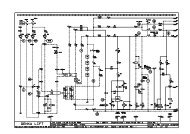
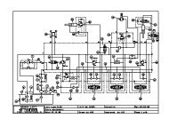
3.1 - WIRING DIAGRAM E 591A (PRESSURE SWITCH VERSION)3 Repair manual1 2 3 4 5 6 7 8 9 10 11 12 13 14 15 16 17 18 19 20 2111 11 116(1)RCHA1111110V - 220VSA31111111004 1316SM111SB2(2)6GD81B35HMU3411 10 9 5 14 1 3 611(4)61 1623438C34354140383752395136(8)1B4B2B12B1A7 A6 A9 B5 B1336(01-3)88HL4GVHSDirectionSteeringHors neutreNull positionHomme mortDeadmanConsigneCursorT O NSA1Mvt1110ADC2 B-9 610 6FU31HL55858SB35C4U29111196C1 B+E43HL19HL69549944(9)(01-9)(01-8)10(3) (6) (5) (7)9SB1aSB1F99106219 9SA2101100G999911SQ1010AFU4300AFU1SQ59KA1(01-2)SQ310010A3H32P11005973SQ4PT1FU2SQ6MDIGB1SQ192 1 6 5 3I5843543029333128494847464512151439938 27 4 34 30 31 32 33 2337 2624 25 36 29 11 21 13 21015959AlarmeAlarmHautHightBasBottomDroiteLeft SteeringCoupure 10m C1210 meters cut C12SurchargeOverloadindicateurindicatorDeversTiltDescenteLowerVoyant SurchargeMontØe Overload LightLiftU1PotholePF/CHAUEmergency StopJB+BUZZERDescente C12Lower C12GaucheRight SteeringDescente > SQ1Lower > SQ1ContacteurMain ContactorK100U1DescenteLowerPV-GVLS-HSGVHSGVHSMARReverseMAVForwardMontØeLiftLibreFreeOption phare de travailWorking light optionSA43Option feu ØclatsFlashing light optionM1100607VMNPB-4100L12 5 4210 9 8 7 16 20 19 18 3 176402726252423502221201918614216rch44HL336HL2YV2b YV3 YV4 YV9 YV5a YV5b YV6 YV7 YV8YV2aYV117(01-12)100MSB1(01-11)HA1100100KA177 7777 7KlaxonHorn100NBRE TOTAL DE FOLIOSIND DATE MODIFICATIONVISAa 12-09-2003 Voy Pesage LDFE591COMPACT 8-8W-10N-10-12 & OPTIMUM 6-8DATE DE CREATIONDESSINE PAR312-09-2003Laurent DI FLORIOPINGUELY-HAULOTTE01SCHEMA PRESDATE DE VERIFICATIONVERIFIE PARTEL: 04 77 29 24 2412-09-2003FrØdØric DENEZELa PØronniŁreBP 942152 L’HORME18
Repair manual 33.1.1 - Electric components : pressure switch versionComponentDescriptionFU1Power fuseFU2Chopper output protective fuseFU3Controls protective fusetFU4Working light protective fuseGB1BatteryHA1BuzzerHL1Situation light indicatorHL2Flashing lightHL3Working lightHL4Lifting light indicatorHL5Machine travel light indicatorHL6Weighing light indicatorM1Motorpump unitPT1 M.D.I displayRCHBattery charger relaySA1Control post selectionSA2Movement selectionSA3Platform travel / lifting selectionSA4Working light switchSB1Battery cut-off / Emergency stop (chassis)SB2Emergency stop (platform)SB3Buzzer controlSM1ManipulatorSP1Pressure switchSQ1Low position contactorSQ10Tilt sensorSQ3Top position contactorSQ4Travel interruption switchSQ5/SQ6Pothole system outUBattery chargerU1Electronic chopperU2Serial cardYVElectrovalve19
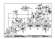
3.2 - WIRING DIAGRAM E591A : WEIGHING CARD VERSION3 Repair manual1 2 3 4 5 6 7 8 9 10 11 12 13 14 15 16 17 18 19 20 211111116(1)RCHA1111SB2220V - 110VSA3111111100164 13SM18(2)6GD111B35HMU343 614 13811 10 9 511(4)61 16234C34354140383752395136(8)1(01-3)886A7 A6 A9 B5 B13 B1 B12 B2 B4SB3 HL4MvtGVHSDirectionSteeringHors neutreNull positionHomme mortDeadmanConsigneCursor11T O NSA110AD58C2 B-C4U291110 6FU3HL558996511C1 B+E43HL19HL69549944(9)(3) (6) (5) (7)FJ4.1J4.4J4.6387J10.3J15.3GJ11.110A300<strong>AJ</strong>4.5J11.310AHJ4.3CARTE PESAGEWEIGHING CARD U3J4.2PT1J9.2 J9.3MDI3 321(01-9)(01-8)109SB1aSB1991061938499A1SA2SQ7101100938138611SQ10FU4FU1388386G1382GSQ510099100KA1(01-2)281 2SQ3SQ832100100597SQ4387FU2SQ6GB1SQ192 1 6 5 3I584354302933312826184948474645991215145938 27 4 34 30 31 32 33 2337 2624 25 36 29 11 21 13 2101AlarmeAlarmHautHightBasBottomDroiteLeft SteeringCoupure 10m C1210 meters cut C12SurchargeOverloadindicateurindicatorDeversTiltDescenteLowerMontØeLiftU1PotholePF/CHAUEmergency StopJB+BUZZERDescente C12Lower C12GaucheRight SteeringDescente > SQ1Lower > SQ1ContacteurMain ContactorKU1DescenteLowerPV-GVLS-HSGVHSGVHSMARReverseMAVForwardMontØeLiftLibreFreeVoyant PesageWeighing Light100Option phare de travailWorking light optionSA43Option feu ØclatsFlashing light option7VMNPB-L12 5 42 4010 9 8 7 616 20 19 18 3 1716252423502220196142rch100 6059M110041002726262118184436HL2 HL3YV8YV7YV6YV5bYV5aYV9YV4YV1 YV2a YV2b YV317(01-12)100MSB1(01-11)HA1100KA1777 7777KlaxonHorn100NBRE TOTAL DE FOLIOSIND DATE MODIFICATIONVISAa 12-09-2003 Voy Pesage LDFE591COMPACT 8-8W-10N-10-12 & OPTIMUM 6-8DATE DE CREATIONDESSINE PAR312-09-2003Laurent DI FLORIOPINGUELY-HAULOTTE01SCHEMA EURDATE DE VERIFICATIONVERIFIE PARTEL: 04 77 29 24 2412-09-2003FrØdØric DENEZELa PØronniŁreBP 942152 L’HORME20
Repair manual 33.2.1 - Electric components : weighing card versionComponentDescriptionA1Weighing angle sensorFU1Power fuse 300AFU2Chopper output protective fuseFU3Controls protective fuseFU4Working light protective fuseG1Pressure sensorGB1BatteryHA1BuzzerHL1Situation light indicatorHL2Flashing lightHL3Working lightHL4Lifting light indicatorHL5Machine travel light indicatorHL6Weighing light indicatorM1Motorpump unitPT1 M.D.I displayRCHBattery charger relaySA1Control post selectionSA2Movement selectionSA3Platform travel / lifting selectionSA4Working light switchSB1Battery cut-off / Emergency stop (chassis)SB2Emergency stop (platform)SB3Buzzer controlSM1ManipulatorSQ1Low position contactorSQ10Tilt sensorSQ3Top position contactorSQ4Travel interruption switchSQ5/SQ6Pothole system outUBattery chargerU1Electronic chopperU2Serial cardU3Weighing cardYVElectrovalve21
223 Repair manual
Repair manual 34 - ELECTRIC COMPONENTS’ DESCRIPTION4.1 - CH<strong>AS</strong>SIS CONTROL POSTSB1SA1 PT1 SA2U1• SB1• SA1• SA2• PT1• U1• RCH• Main switch including battery-cut-off function• Key contactor : selection of the command either on the top console with the possibility to take off the key,or on the turntable console with no need to maintain the command.• Command switch driving the platform up or down. 14 Up, 15 Down• Multifunction indicator (hour recorder, unloading indicator and numeric indicator of codes statements)• Chopper• Battery charger relay4.1.1 - Switches (E591a - Pressure switch version)SQ4 SQ1 SQ3 SQ5 SQ6SQ10 TILT SENSOR TEST MODE =0SP1• SQ1 • Low position switch : wire 28 ; 1 = low position of the platform ; 0 = high position of the platform.• SQ3 • Low position switch; wire 29, gets on position 0 at the end of lifting and cuts the lifting command.• SQ4 • Position switch to stop traveling at a platform height of 8 meters from the floor: wire 31• SQ5 & SQ6 • Position switch to control the extension of potholes. The wire 31 of this circuit must be closedbefore SQ1 gets on 0 ; otherwise it prevents lifting and traveling. Lowering is the only solution left.• SQ10 • Slope : wire 12 ; 1 at rest ; 0 = tilt• SP1 • Pressure switch wires 2823
3 Repair manual• FU2 10A• FU3 10A• FU4 10A :• FU1 250A• M1: .4.1.2 - Fuses and motors• Command fuse : protection of solenoid valves and horn.• Command fuse to feed the command circuit. It protects the whole command circuit.• Fuse protecting the feeding of the optional circuit of working head lights or flashing lights.• Power protection fuse.• Pump motor 24V 3000W4.2 - PLATFORM CONTROL POST EQUIPMENTSM1HA1HL5HL1HL6HL4SA3U2SB2• U2 • The serial card allows compiling the different elements of the console in order to get a digital transmissionsignal.• SM1 • Joystick• SA3 • Switch selecting either lifting or slow & high travel speed.• SB2 • Upside console emergency push button• HA1 •Buzzer• HL1 • Light visualising alarm codes (Flashing codes)• HL4 • Light visualising travel motion position : slow or high travel speed of SA3• HL5 • Light visualising lifting position of SA3• HL6 • Weighing light indicator4.3 - SOLENOID VALVES• YV1 • Solenoid valve selecting travel or up & down operations. At rest it controls travel, working it drives liftingwire 18.• YV2A • Solenoid valve that controls the forward gear wire 19• YV2B • Solenoid valve that controls backward gear wire 20• YV3 • Solenoid valve that controls high or low travel speed. At rest : low speed, working : high speed wire 21• YV4 • Solenoid valve that controls high or low travel speed ; at rest : low speed, working : high speed ; wire 22• YV5A • Solenoid valve that controls steering right• YV5B • Solenoid valve that controls left steering• YV6 • Solenoid valve that controls the potholes’ spreading out movement only when SQ1 is on 1.• YV7 • Solenoid valve that pilots the low cylinder lowering; wire 26.• YV9 • Solenoid valve : principal descent : ON when SQ1 is = 0 wire 50.24
Repair manual 34.4 - END OF TRAVEL SWITCHES CHARTSwitchMovement toperformRecommended adjustmentOptimum 6 Optimum 8CheckEnd of travel -lifting (SQ3)Pothole end oftravel(SQ5 & SQ6)SQ1 - Fin decourseréarmementdévers• Lifting4.33 m+/-15 cm5.80 m+/-15 cm• Lifting movement cut-off inhigh position• Lifting - - • Potholes’ extension whenthe plateform is raised at1.5 m• Microspeed activation• Disconnect YV6- - • Lifting movement impossible• Liftingabove 1.5 m• Travel movement impossibleabove 1.5 m• Liftingabove 1.5m andlowering1.75 m+/- 10cm1.75 m+/- 10cm• Check that the loweringmovement is properlyperformed ; the movementmust be interrupted at 1.5 m.4.5 - SERIAL CARDAB6 7 9 8 1 2 4 5 12 13C3214A B CA7 – Wire 51A9 – Wire 39A6 – Wire 52AcceleratorpotentiometerB1 wire 40 : Left steering switchB12 wire 41 : Right steering switchB13 wire 38 : Except neutralB5 wire 37 : Dead man switchB2 wire 35 : Travel selectionB4 wire 34 : Movement selectionB8 wire 36 : HornC1 : battery +C2 : battery –C4 : battery signal25
3 Repair manual4.5.1 - Serial card initialization• Emergency stop not pressed.• Put the key on OFF (stop).• Shunt the serial card (J1) with the help of a crimp.• Put the key on ON (start), and operate as follows, slowly:- 1.Advance high speedReturn to neutral positionRelease the joystick- 2.Backward movement high speedReturn to neutral positionRelease the joystick- 3.ClimbingReturn to neutral positionRelease the joystick- 4.Going downReturn to neutral positionRelease the joystickWhen these operations have been done, release the shunt.• Wait 5 seconds.• Put the key in position OFF.• Test the platform.4.6 - MDIThe state of charge of the batteries is displayed through a series of 5 LED’S.• 4 yellow LEDs (4 LEDs lit = batteries charged).• 1 red LED (signals that the battery unit is discharged).Hour meterA liquid crystal alphanumerical display unit situated at the centre of the chargeindicator dial informs the user about the number of hours performed.AlarmsThe same display unit used for the hour meter also plays the part of a state ofalarm indicator providing a code corresponding to the type of alarm reported. Thered LED flashes in order to attract the user’s attention.Software versionOn switching off the key, the eeprom version is displayed on the dial for a fewseconds (EPXXX where XXX represents the version). The English key symbolalso appears during this phase.26
Repair manual 34.7 - USING THE ON-BOARD CHARGERCaution!Set the chassis’ emergencystop button on the ’OFF’position before recharging.4.7.1 - CharacteristicsTraction batteries must be charged with the charger provided. DO NOTOVERCHARGE THEM• Charger: 24V - 30A• Power supply: 220V single phase - 50 Hz• Operating voltage: 24V• Charging time: approximately 11 hours for batteries discharged by 70% to80%Caution!In cold weather, the chargingtime increases.4.7.2 - Starting the chargePhoto 1Charging is started automatically when the charger is connected to the mains.The charger is equipped with a light indicator:• the indicator shows the current state of charge.StateRED onYELLON onGREEN onDescriptionMachine charging80% chargedMachine charging complete4.7.3 - Maintenance chargingIf the charger remains connected to the mains for more than 48 hours, it starts acharge cycle after the end of the previous charge in order to compensate for selfdischarge.4.7.4 - Charge interruptionCharging is stopped by disconnecting the charger from the mains. If the machinehas to be moved during a charge cycle, the charger must be disconnected. Thismay reduce battery life. After movement, reconnect the charger.4.7.5 - Precautions of use• Avoid recharging batteries if the electrolyte temperature is higher than 40°C.Leave to cool.• Keep the top of the batteries dry and clean. Incorrect connection or corrosionmay lead to serious power loss.• If new batteries are used, re-charge them 3 to 5 times after 3 or 4 hours’ use.• The charger has been configured in the plant with the cable provided. If thecable needs replacing, contact PINGUELY-HAULOTTE for authorisation.27
3 Repair manual4.8 - CHOPPER4.8.1 - Terminal-wire connections chartTerminal Wire Terminal Wire Terminal Wire1 Not in use 15 Not in use 29 39 Top position end oftravel input (SQ3)2 58 Input - 16 50 Lifting solenoid 30 45 MDI signalvalve output YV93 26 Lowering control YV7 17 27 Not in use 31 46 MDI signalsolenoid valve4 9 Input + 18 25 Pothole command32 47 MDI signalsolenoidvalve YV65 16 Output SB1control 19 24 Left steering solenoidvalve controlouputYV5b33 48 MDI signal6 22 OutputYV4 HS control7 21 OutputYV3 HS control8 20 OutputYV 2 b Reverse gearcontrol9 19 OutputYV2a Forward gearcontrol10 18 Output supplyingYV1 : travel movementselection11 54 Input – indicator lightDefault indicator20 23 Right steeringsolenoid valvecontrol ouputYV5a21 43 Series signalinput34 11 Top control panelvalidation35 Not in use22 12 Not in use 36 31 + Batterie23 49 MDI signal 37 14 Chassis lifting control24 33 Pothole end oftravel input (SQ5and SQ6)25 29 Low position endof travel input(SQ1)38 15 Chassis loweringinput39 Not in use12 44 Horn control 26 28 Overload pressure40 61 Not in useswitch input(SP1)13 9 Input + 27 12 Tilt indicator 41 Not in usesignal14 Not in use 28 Not in use 42 42 SB1control output28
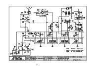
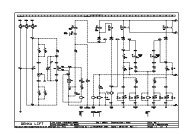
Repair manual 35 - HYDRAULIC DIAGRAM5.1 - HYDRAULIC DIAGRAM FOR OPTIMUM 6 AND 8 (B16288B) MODELESSIEU AVANTFRONT AXLEBB A1/2" BSPP 1/2" BSPP 1/2" BSPP 1/2" BSPPFREIN ESSIEU ARRIEREREAR AXLE BRAKE57/16 -20 UNF"7/16 -20 UNF"POTHOLES5o32/20course851/4"1/4"1/4" 1/4"DIRECTIONSTEERINGo40/20course114LEVAGE - LIFTINGo80/60course8466741/4"YV 73/8"A1 3/8" A2 3/8" A3 3/8" A4 3/8" FR 1/4"B1 1/4" B4 1/4" B2 1/4" B3 1/4" C1 3/8" D1 1/4" D2 1/4"YV 3YV 6YV 4YV 2 aYV 2 bPression selon chargePressure accprdong to loadYV 9o1.2mmYV 5aYV 5bYV 1230 bar110 barMX1/4"T 1/2" P 3/8"3/4"3 23/4"M3000 W24 V5.53/8"13/4" 3/8"3/4"20 LRESERVOIR - TANK1/2"5.1.1 - ComponentsPart Marker Qty Comments2420703820 – Motor pump unit 3KW 24V 1 12427010430 – Oil filter 3/4 BSPP 2 12420212090 - MK4 distribution block 3 12431202110 – Hydraulic motor 162cm3 4 2118C149380 - Cylinder SP.5090-5093 5 2118C170040 – Lifting cylinder 6 129
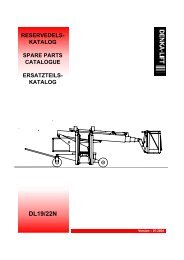
5.2 - HYDRAULIC INSTALLATION DIAGRAM A14681D3 Repair manualFREIN ARRIEREGAUCHELEFT BACKBRAKEVERIN DE LEVAGELIFT CYLINDERVERINPOTHOLEGAUCHELEFT ANTI-TIPPINGOVER DEVICECYLINDERMOTEUR AVANTGAUCHELEFT FRONTMOTORVERIN DEDIRECTIONSTEERINGCYLINDERMOTEUR AVANTDROITRIGHT FRONTMOTORS10S101/2"BSPP401/2"BSPPS10S10S10 S10S10S101/2"BSPP1/2"BSPP6S103/8"S183/4"S61/4"1/4"S6VERINPOTHOLEDROITRIGHT ANTI-TIPPINGOVER DEVICECYLINDERS103/8"1/2"S18S18POMPEPUMPS10S163/4"RESERVOIR 22L22L TANK8S67/16-20 UNF3/4"3/4"S16S16FILTREFILTER3/8"1/2"1/4"1/4"1/4"Limiteur de pression <strong>general</strong>eMain pressure limiter3/8"3/8"3/8"3/8"3/8"1/4"1/4"Limiteur de pression directionSteering pressure limiterRobinet mise en roue libreBrake release valveLimiteur pression levageLift pressure limiterRobinet défreinagemanuel/1/4"S6 S61/4"Brake release valve (manual)1/4"S67/16-20 UNFFREIN ARRIEREDROITRIGHT BACKBRAKES6A14681dS6S63630
Repair manual 35.2.1 - Components listed in diagram A14681dA14681d - Parts Marker Qty Comments2369117210 – Union piece M.JIC 37 1 12369117190 - Union piece M.JIC 37 2 12369110160 - Union piece M.JIC37 (16)M 3/4 BSPP 3 12369110170 - Union piece M.JIC37 (16)M 1/2 BSPP 4 12369117370 - Union piece JIC 37 BS 5 42369117360 - Union piece M JIC37 6 92369117120 - Union piece M.JIC 37 7 62369111440 - Union piece male JIC37( 6)M.7/16-20 UNF 8 22369109100 - Union piece TC M.JIC 37 (10) 9 22369132200 – Adjustable bend M.JIC37 10 22369132090 - Bend 7 90° 11 72369135180 – Bend 37 90° 12 12369147000 – Equal T piece JIC 37 13 12441604150 – Minimess tap 1/4' G 14 12369073050 - Hose S5241 Lg 290 D-C90 15 12369073040 - Hose S5028 Lg 1130 D-D 16 12369073030 - Hose S5028 Lg 420 D-D 17 12369073310 - Hose S5415 Lg 2050 D-C135 18 12369070890 - Hose SP.1756 1,750m 19 12369071650 - Hose SP. 5250 2,050m 20 12369073000 - Hose S5250 Lg 2000 D-C90 21 22369072890 - Hose S5250 Lg1850 22 12369058550 - Hose S1756 LG 1m 23 12369073080 - Hose S1756 Lg 2350 D-D 24 12369073300 - Hose S5250 Lg 2400 D-C90 25 12369071160 - Hose S1707 2,19m 26 22369073020 - Hose S1707 Lg 1660 D-D 27 22369070260 - Hose S1707 Lg 1550 D-D 28 12369072380 - Hose S1707 1.47m 29 12369072530 - Hose Lg 860 D-C90 30 12369071800 - Hose SP. 5238 0,530m 31 12301231750 - Screw H M8X80/22 CL8.8 ZB 32 12421608490 – Protective plate GD2-D 33 12389003250 - Collar 216/16 PP 34 22349221500 - Nut M8 CL8ZB 35 12389002540 - Collar 36 1118D160570 - Washer Ø36/27 ep=2 37 2118D160560 - Washer Ø23,5/17 ep=2 38 12421903390 – Flexible plastic spiral 900952-12 39 1 0,31m2421903430 - Flexible plastic spiral 40 2 2 m31
323 Repair manual
Repair manual 36 - DESCRIPTION OF THE HYDRAULIC CIRCUIT6.1 - HYDRAULIC BLOCK’S COMPONENTS1 2 3 4 5 6 7 8 9Marker Part Description1 YV3 244 050 7620 Parallel serial coupling Low speed / High speed travel2 YV4 244 050 7610 Parallel serial coupling Low speed / High speed travel3 YV2 244 050 8580 Solenoid valve selecting direction of travel4 YV6 244 050 8590 Pothole control solenoid valve5 YV1 244 050 7590 Travel/ lifting selection solenoid valve6 FRT 242 220 4980 Priority valve7 RV2 242 120 3240 Main pressure regulating valve8 RV3 242 120 3510 Lifting pressure regulating valve9 YV 244 050 8570 Steering solenoid valve10 RV1 242 120 3520 Steering pressure regulating valve11 FD1 242 040 2610 Travel flow divider12 CB2 242 220 5310 Balancing valve13 CB1 242 220 5310 Balancing valve33
3 Repair manualMarker Part Description15 FR Rear brakes power supply output16 YV3 244 050 8560 Lifting solenoid valve17 NV1 242 180 8630 Brake release discharge valve18 NV2 242 180 8630 Balancing valves by-pass valve14 242 160 9590 Hand pump23 30 24 26 28 3734323135 25 33 29 36Block’s outputMarker Part - description Marker Part - description23 A1 - Front left travel motors power supply output 31 MX - Minimess tap output – port gauge24 B1 - Pothole re-entry block output 32 D1 - Steering cylinder power supply output25 B4 - Pothole re-entry block output 33 B3 - Pothole spreading out device26 B2 - Potholes spreading out device 34 A2 - Front left travel motors power supplyoutput28 C1 - YV9 lifting power supply output 35 A3 - Front right travel motors power supplyoutput29 T - Block output for returning to the tank through 36 P Block input taken on the block’s outputthe hydraulic filter30 A4 - Front right travel motors output 37 D2 Steering cylinder power supply output34
Repair manual 36.2 - MK4 HYDRAULIC BLOCK SPECIFICATIONSHaulotte referenceMaximum pressure: 240 barHaulotte reference: 242 021 2090Flow: 18 l/minute35
3 Repair manualRIGHT SIDE VIEW REAR VIEW2 tapped holes M 8Depth: 1336
Repair manual 3FRONT VIEW37
383 Repair manual
Repair manual 36.2.1 - List of components (Page 5 of 5 in S5625)Marker Description Haulotte reference1 Priority valve 242 220 49802 Main pressure regulating valve 242 120 32403 Lifting pressure regulating valve 242 120 35104 Steering pressure regulating valve 242 120 35205 Screw-in cartridge electrovalve 244 050 75906 Screw-in cartridge electrovalve 244 050 85807 Screw-in cartridge electrovalve 244 050 76108 Screw-in cartridge electrovalve 244 050 76209 Screw-in cartridge electrovalve 244 050 859010 Screw-in cartridge electrovalve 244 050 856011 Screw-in cartridge electrovalve 244 050 857012 Flow divider 242 040 261013 Balancing valve 242 190 531014 Hand pump 242 160 959015 Spray nozzle (Orifice plug) 242 070 351016 Block 242 021 210017 Plug 242 020 989018 Safety valve 242 180 86306.3 - HYDRAULIC FUNCTIONING6.3.1 - Operating equation• Steering- Right =YV5 A- Left =YV5 B• Lifting- YV1 + YV6 (When < SQ1)• Descent- > SQ1 =YV9 + YV 7 + YV 8( if C12) +YV6- < SQ1 =YV 7 + YV 8( if C12)• Travel motion- Slow speed frontward gear: YV2A- Slow speed backward gear: YV2B- High speed frontward gear: YV2A + YV3 + YV 4- High speed backward gear: YV2B + YV3 + YV 439
3 Repair manual6.3.2 - Solenoid valves’ functioningCommon hydraulic diagram for compact and optimum machinesFront axle Brake Steering Liftingrear axle6.3.3 - Direction of travel and anti-rolling selectionBalancing valve +one-way valveForward or reverse gearselection solenoid valve40
Repair manual 36.3.4 - Speed selectionForward gear slow speed(travel motor in parallel)Forward gear high speed(travel motor in series)Reverse gear slow speed(travel motor in parallel)Reverse gear high speed(travel motor in series)6.3.4.1 -Fonctioning of balancing valvesThe solenoid valve in use is that placed on the return position ; its main roleconsists in keeping an equilibrium in the travel circuit pressures and ensuring aconstant speed preventing the machine from rolling when on ramps. In thefollowing diagram we shall consider that the machine is in forward gear.YV1 - Travel / movement selection solenoid valveOil circulationis stopped on the valveOil circulates throughthe one-way valveAccumulation of pressureon both control pipes allowsopening the balancing valve.Towards T returnTowards P supply41
3 Repair manual6.3.4.2 -Rear wheels’ brake release power supplyPressure being present in thetravel pressure pipe feeds thebrake release device.Potholes’s supply6.3.4.3 -Potholes’ functioningWhen using the lifting command, hydraulic oil circulation is supervised throughthe following solenoid valves :• YV1 (in operation position)Travel/lifting selection. In the lifting position the oil is directed towards the loweringsolenoid valve as indicated in the diagram above, by passed during lifting and onthe two pothole cylinders chambers. The oil present in the small chambers is sentback to the tank through the YV6 solenoid valve. This solenoid valve will bepowered as long as the machine is under the SQ1 switch.• YV6: Pothole control solenoid valve.Liftingpower supply42
Repair manual 3LoweringPotholes’ re-entryon starting a travelmovement underSQ143
6.3.5 - Steering funtioning3 Repair manualIn the hydraulic block input, the oil first passes through a priority valve. The latterpowers steering through a priority flow.It is necessary that YV1 be at rest (Travel selection)The choice of YV5A or B depends on the direction requested for steering.Right or left cylinder power supply outputaccording to the direction requested.Priority flowPriority valveNon priority flowPump output flowFilter onreturnHydraulic tank: 27 l / 7 gallonMotor pumprun by thechopper44
Repair manual 37 - MAINTENANCE7.1 - GENERAL RECOMMENDATIONSCaution!Do not use the machine as awelding ground.Do not weld withoutdisconnecting the (+) and (-)battery terminals.Do not start other vehicleswith the batteries connected.Servicing operations described in this manual are given for normal conditions ofuse.In difficult conditions: extreme temperatures, high hygrometry, pollutedatmosphere, high altitude, etc., certain operations must be carried out morefrequently and specific precautions must be taken: consult the PINGUELYHAULOTTE After-Sales Service for information.Only authorised and competent personnel may operate on the machine and mustcomply with the <strong>safety</strong> instructions related to Personnel and Environmentprotection.Regularly check that the <strong>safety</strong> systems work properly:1°) Tilt: buzzer + stop (travel and lifting disabled).2°) Platform overload - load.7.2 - MAINTENANCE DEVICEThe maintenance stand enables the operator to work under the machine in total<strong>safety</strong>.Photo 2Operating instructions:(Photo 2, page 45)These operations are to be carried out on both sides of the platform.Putting the maintenance stand into place:• Position the platform on a firm, horizontal floor.• Ensure that the two emergency stop buttons are "ON".• Turn the chassis ignition key to the "Chassis" position.• Push the chassis lifting switch up to raise the platform.• Unscrew and turn the maintenance stand and allow to hang vertically.• Push the lifting switch down to lower the platform gradually until the maintenancestand comes up against the two fixing points (top and bottom).Removing the maintenance stand:• Push the chassis lifting switch up and gradually raise the platform until themaintenance stand is free.• Turn the maintenance stand until it comes into its storage position and screwback into place.• Push the chassis lifting switch down and lower the platform completely.45
3 Repair manual7.3 - ELECTRICITY SUPPLYPhoto 3Operating instructions:Cutting off the electricity supply:Press the chassis emergency stop (Photo 3, page 46).Starting the electricity supply:Reset the emergency stop.7.4 - MAINTENANCE PLANThe plan (overleaf) indicates frequency, servicing points (device) and theconsumables to be used.• The reference in the symbol indicates the servicing point according to thefrequency.• The symbol represents the consumable to be used (or the operation to beperformed).7.4.1 - ConsumablesConsumable Specification SymbolHydraulic oilOrganic hydraulic oil(option)’Intense cold’ hydraulicoilLithium greaseExchange or specificoperationAFNOR 48602ISO VG 46BIO ISO 46ISO 6743-4Lubrifiers used byPinguely-HaulotteBPSHF ZS 46SHELL TELLUS 32SHELL ALVANIA EP(LF) 3ELFHYDRELFDS 46TOTALEQUIVISZS 467.4.1.1 -’Intense cold’ hydraulic oil conditions of useThis oil is meant for working at low temperature.Caution!The ambient temperature must not exceed 15°C. In the opposite case, use46
Repair manual 37.4.2 - Maintenance diagram16 4 3 541214715 1610502505001 000193 00023109 1110 81717181913502505001 0003 00047
3 Repair manual7.5 - OPERATIONS7.5.1 - Summary tableIMPORTANT: If "ORGANIC" OR "EXTREME COLD" OIL IS USED,FREQUENCIES IN THE TABLE BELOW ARE REDUCED BY HALF.FREQUENCY OPERATIONS REFEvery day or beforeeach start ofoperationEvery 50 hoursEvery 250 hours• Check presence and legibility:- of CE manual,- of danger warning stickers,- of instruction stickers.• Check presence of screws etc.• Check levels of:- hydraulic oil (see paragraph 8, sheet P001 )- battery electrolyte.• Check the condition of:- wheel solid tyres,- battery charge on the discharge indicator,- wear of the hydraulic hoses,- hydraulic connections (no leaks),- electric cables and wiring harnesses (no corrosion orstripped areas),- wear of scissor arm slides and pads.• Check proper operation of the tilt detector.• Only the first 50 hours- change the hydraulic filter (see paragraph 8, sheet P002 ).• Check the tightness:- of screws etc. in <strong>general</strong>,- front motor fixing screws (9 daNm),- rear brake fixing screws (9 daNm),- front wheel nuts (25 daNm),- rear wheel nuts (25 daNm).• Check:- the condition of electric cables (change if corroded),- density of battery electrolyte,- no battery electrolyte leaks.• Check:- the connection of the battery charger,- no cylinder leaks.• Grease:- wheel pivot pins (see paragraph 8, sheet P003 ),- friction parts of the scissor arm slides (see paragraph 8,sheet P004 ).• Change the hydraulic oil filter.• Clean the motor-pump unit ventilation hole.Every 500 hours • Oil change: organic hydraulic oil tank (option) 17Every 1000 hours orevery yearEvery 3000 hours orevery 4 years• Empty:- the hydraulic oil tank,17- the hydraulic circuit.• Clean the motor-pump unit carbon.18• Adjust the pressure limiters.• Check ring wear.• Replace:- hydraulic circuit hoses,- batteries. 191234567891011121314151648
Repair manual 3REMINDER:All these frequencies must be reduced if working in difficult conditions(consult After-Sales if necessary).7.6 - PRESENCE OF LABELS7.7 - PRESENCE OF MANUALSIt is important to check that the labels and plates warning personnel of the variousdangers associated with using the machine are in good condition.The labels providing operators with information on machine use and maintenancemust also be checked.An illegible label may lead to incorrect or dangerous use of the machine.Operating instructions:Check the presence of the labels:Check that all the labels described in the operator’s manual are legible and in thecorrect place. Replace if necessary (spare parts can be supplied on request, ifnecessary).It is important to ensure that the manuals supplied with the machine are in goodcondition and stored in the document holder provided on the platform.An illegible manual may lead to incorrect or dangerous use of the machine.Operating instructions:Check presence of manuals:Check that all the manuals are legible, complete and stored in the documentholder provided on the platform. Replace if necessary (extra copies can besupplied on request by the manufacturer).49
503 Repair manual
Repair manual 38 - PREVENTIVE MAINTENANCE SHEETSList of preventive maintenance sheets:Sheet no.P001P002P003P004DescriptionChecking - filling the hydraulic oil tankReplacing the hydraulic filter cartridgeGreasing the steering wheel pivotsGreasing the slides51
523 Repair manual
SHEET P001PREVENTIVE MAINTENANCE SHEETCHECKING THE HYDRAULIC OIL TANK LEVELSheet 1/11 - Preliminary operations• Put the machine in the low position and maintenance configuration (see§7.2, page49).Caution !Ensure that oil temperatureis not too high.NOTA :Do not use the maintenance stands, leave the platform in the low position.• Cut off the electric power supply (see § 7.3, page 50).2 - Checking the hydraulic oil tank level• Ensure that the oil level in the tank is sufficient.• Top up if necessary.NOTA :Only use the oil recommended by the manufacturer.• Put the machine back into operational configuration.MAXMINOIL LEVEL
PREVENTIVE MAINTENANCE SHEET
SHEET P002PREVENTIVE MAINTENANCE SHEETREPLACING THE HYDRAULIC FILTER CARTRIDGESheet 1/11 - Preliminary operationsCaution !Ensure that oil temperatureis not too high.•Put the machine in the maintenance configuration (see § 7.2, page 49).•Cut off the electric power supply (see § 7.3, page 50).2 - Replacing the hydraulic filter cartridge•Unscrew the body and remove the hydrualic filter cartridge.•Screw a new cartridge into place.•Put the machine back into the operational configuration.CompactOptimum
PREVENTIVE MAINTENANCE SHEET
SHEET P003PREVENTIVE MAINTENANCE SHEETGRE<strong>AS</strong>ING THE STEERING WHEEL PIVOTSSheet 1/11 - Greasing the steering wheel pivots•Cut off the electric power supply (see § 7.3, page 52).•Grease the pivots.NOTA :Only use the grease recommended by the manufacturer.Compact, optimum, previousdesign.•Put the machine back into the operational configurationCompact, optimum, currentdesignStar 22J / Star 8
PREVENTIVE MAINTENANCE SHEET
SHEET P004PREVENTIVE MAINTENANCE SHEETGRE<strong>AS</strong>ING THE SLIDESSheet 1/11 - Preliminary operations•Put the machine in the maintenance configuration (see § 7.2, page 51).•Cut off the electric power supply (see § 7.3, page 52).2 - Greasing the slides•Grease the slides using a spatula.NOTA :Only use the grease recommended by the manufacturer.•Put the machine back into the operational configuration.
PREVENTIVE MAINTENANCE SHEET
Repair manual 39 - OPERATING INCIDENTS9.1 - TABLE OF INCIDENTSBefore anything else, check that:• the batteries are charged; the green light indicators should be on.• the two "palm button" emergency stops on the chassis control box and onthe platform control box are unlocked.• the oil level in the tank is OK.Caution!Bubbles + pressure + heat =unacceptable situation.Risk of explosionNB:Cavitation (emulsified oil) may cause incorrect operation of hydrauliccomponents. It takes approximately 4 hours for oil that has beenemulsified under the effects of cavitation to get back to its normalcondition.9.1.1 - General operationANOMALY CHECK PROBABLE CAUSE SOLUTIONNo movement• Defective batteries• Oil level low• Defective fuses• Defective chassis emergency stop• Defective platform emergency stop• Defective wiring harness• Defective motorpump set• Defective printed circuit• Defective control unitSHEET DP007Hydraulic pump noisy• Insufficient oil in the tank• Defective pumpSHEET DP009Pothole system doesnot extend when theplatform is raised• Defective speed variator• Defective wiring harness• Defective electrovalve YV6 coil• Defective electrovalve YV6• Defective pothole cylindersSHEET DP013No movement from theplatform control station• Defective key switch SA1• Defective electric wiring harness• Defective speed variator• Defective manipulator• Defective printer circuit U2SHEET DP014Hydraulic pumpcavitation(Vacuum in the pumpdue to insufficient oil).The hydraulic oilbecomes cloudyand white (withbubbles)• Oil viscosity too high• Empty the circuit andrefill with the recommendedoil.61
3 Repair manualANOMALY CHECK PROBABLE CAUSE SOLUTIONOverheating of thehydraulic circuitThe system worksirregularly• Oil viscosity too high• Insufficient hydraulic oil in the tank• The hydraulic oil is not at optimumoperating temperature9.1.2 - Platform lifting system• Empty the circuit andreplace with the recommendedoil. Topup with oil as necessary.• Make some movementswithout load toenable the oil to heatupANOMALY CHECK PROBABLE CAUSE SOLUTIONNo up or downmovement from theplatform controlNo up or downmovement from thechassis controlNo up movement fromthe chassis or platformcontrolsNo down movementfrom the platform orchassis controlsThe platform (above1.5m) comes downslowly by platform orchassis controlsThe platform moves upand down with a jerkymovement• Defective wiring harness• Defective printed circuit U2• Defective manipulator• Defective platform emergency stopbutton• Defective speed variator• Defective key switch• Defective wire no. 10• Defective switch SA2• Defective speed variator• Hydraulic leak• Defective wiring harness• Defective electrovalve YV1 coil• Defective lifting cylinder• Defective electrovalve YV1• Defective or badly adjusted limiter• Defective tilt detector• Defective speed variator• Defective end of stroke contactor• Defective wiring harness• Badly adjusted or defective pressurecontact SP1• Defective electrovalve YV7 coil• Defective electrovalve YV7• Defective speed variator• Defective electrovalve YV9 coil• Defective electrovalve YV9• Defective electric wiring harness• Defective speed variator• Insufficient oil in the hydraulic circuitSHEET DP001SHEET DP002SHEET DP003SHEET DP004SHEET DP061• Top up with oil as necessary62
Repair manual 39.1.3 - Travel systemANOMALY CHECK PROBABLE CAUSE SOLUTIONNo travel movement ineither direction,FORWARD orBACKWARDNo travel in onedirection, FORWARDor BACKWARDHigh speedunavailable below1.5mOnly micro-speed isavailable below 1.5mThe machine goes intorunaway downhill• No movement available• Defective pothole cylinder• Defective wiring harness• Defective pothole end of stroke contactor• Defective brake• Defective motor• Defective speed variator• Defective wiring harness• Defective YV2a or YV2b coil• Defective electrovalve YV3 or YV4coil• Defective electrovalve YV3 or YV4• Defective wiring harness• Defective printed circuit U2• Defective speed selector switch SA3• Defective speed variator• Defective electric wiring harness• Defective contactor SQ1• Balancing valve incorrectly set or notworking properly9.1.4 - Steering systemSHEET DP062SHEET DP010SHEET DP011SHEET DP012• Replace the balancingvalve.ANOMALY CHECK PROBABLE CAUSE SOLUTIONNo steering• Hydraulic leak• No lifting• Defective printed circuit U2• Defective electrovalve YV5a or YV5bcoil• Defective electrovalve YV5• Defective wiring harness• Defective manipulator• Defective steering cylinder• Defective steering pressure limiterSHEET DP00863
AlarmcodeNumberofflashes(MDI)9.1.5 - List of MDI codes3 Repair manualMessage Description SolutionAL01 3 EVP NOT OK • Defective coil orYV7/YV9 coil’s supply.AL06 6 SERIALERROR #1• Incorrect or lack ofreception of serial card’ssignal to chopper.AL13 6 EEPROM KO • Fault in the chopper’sEEPROM.AL32 3 VMN NOT OK • Low VMN at rest orinconsistent with theapplied VMN at work.AL37 4 CONTACTORCLOSEDAL38 4 CONTACTOROPEN• SB1’s contact stuck. • Check SB1.• SB1’s auxiliary contactfaulty.• Look for failure on the liftingcylinders’ lowering coil(s).• Look for failure on:- the platform console’s serialcard;- the bundle;- the connections between theplatform’s console and thechopper.• Other possible reason: incorrectcabling on the MDI line or theMDI display.• Replace the chopper.• Check the chopper’s isolationbetween B- and P terminals.• If the value is below 65 KOhms,replace the chopper.• Otherwise replace the motor.• Check SB1.AL49 5 I=O EVER • Null current on• Replace the chopper.movement request.AL53 5 STBY I HIGH • High current at rest. • Replace the chopper.AL60 3 CAPACITORCHARGEAL62 9 TH.PROTECTIONAL66 8 BATTERYLOWAL73 1 POWERFAILUREAL74 4 DRIVERSHORTEDAL75 4 CONTACTORDRIVER• Capacitors do notcharge on starting themachine.• Chopper’s thermalprotection: temperatureover 75°C/167F• Batteries discharged.• Short circuit on anelectrovalve’s coil or thehorn or SB1’s coil.• SB1 conctactor’s driverfaulty or in short circuit.• SB1 conctactor’s drivermalfunctioning or willnot close.• Replace the chopper.• Replace the chopper.• Check:- the batteries- the charger- the electric circuit’s supply.• Check:- the electrovalves’ variouscoils,- the horn;- SB1 contactor’s coil.• Defective SB1 or chopper.• Defective SB1 or chopper.64
Repair manual 3AlarmcodeNumberofflashes(MDI)AL78 2 VACC NOT OK • Manipulator at rest. • Check the joystick’s output voltageusing the console’sTESTER mode.• In the case of an incorrect programing,adjust the valuescalibrating the serial card.• Otherwise replace the chopper.AL79 2 INCORRECTSTART• Incorrect startingsequence.AL80 2 FORW+BACK • Backward andforward movements requestedsimultaneously.AL90 4 DRIVER 1 KO • YV6 coil in short circuit.AL93 0 WRONG INPUTCONF.AL94 6 MICROCONTROL KOAL97 5 CURR.PROTECTION• The platform console’sENABLE startingswitch is closed while amovement is requestedfrom the chassis controlpanel.• The Siemens calculatordoes not respondcorrectly.• Current out of control.AL98 0 • The hour shown onthe MDI and the chopperdiffer.AL99 6 CHECK UPNEEDEDMessage Description Solution• The ’Check up’ functionhas been activated.• Check the joystick’s output datausing the console’s TESTERmode, then replace either thejoystick or the chopper,according to the tests’ results.• Check the joystick’s output datausing the console’s TESTERmode, then replace either thejoystick or the chopper,according to the tests’ results.• Check YV6 electrovalve’s coiland its connections.• Replace the chassis controlpanel’s lift switch.• Replace the chopper.• Replace the chopper.• Wait for 6 minutes after puttinginto service.• If the problem remains, connectthe console instead of the MDI.• In this configuration, if the machinefunctions again, MDI fault.• If the machine still does notfunction, defective bundle orchopper.• Deactivate the ’CHECK UPENABLE’ function using theconsole.65
3 Repair manualNB:If no situation and red and green (last) light indicators are on,SPEED VARIATOR is INOPERATIVE.Alarm 01:- if all the green light indicators are on = speed variator inoperative- Check YV7 connector- Disconnect the plug on electrovalve YV7- Take YV1 coil for testing- The fault disappears = replace coil / the fault does notdisappear- Disconnect the plug connecting with the chassis wiringharness- Check the pin of wire 26 for incorrect connection- TestsAlarm 98 :- when replacing the speed variator or MDI, this code mayappear when restarting the machine. In this case, leavethe machine live for approximately 1/4 hour, to allow thespeed variator to re-establish communication with theM.D.I.66
Repair manual 39.2 - FAILURE DETECTION FLOW CHARTS67
683 Repair manual
SHEET DP001FAILURE DETECTION FLOW CHARTNO UP AND DOWN MOVEMENTFROM THE PLATFORM CONTROLSheet 1/2No up and down movement from theplatform controlPlace the movement selectorswitch (SA3) in the position (HS)then in the up position.Check that light indicators HL4 (up)and HL5 (HS) come onOpen the platformcontrol panel andcheckfor 24Vbetween terminals (7)and (4)NOTheLEDs comeonYESNO24Vbetween (7)and (4)YESRepair cabling orreplace switch SA3Open the platform controlpanel and activatethe «fail-safe» and tilt themanipulatorPresenceof setpoint at C4output of printedcircuit U2YESNOCheck the presence of a setpointvalue on input A9 ofprinted circuit U2 and thepresence of 24V on input B5and B13 of printed circuit U2ENDContinuitybetween coils (1) and (2)of the platformcontrol panelNONORenovate cablingbetween terminal C4and output (5) of thecontrol panel or changethe control panel linkwiring harnessENDSee SHEETC004A9 setpointvalue and 24V onB5 and B13YESReplace printedcircuit U2NOYESReplace speedvariator U1ENDChange thecontrol panel linkwiring harnessENDRenovate cabling orchange PB SB2See SHEETC013Replace themanipulatorENDENDEND
SHEET DP001FAILURE DETECTION FLOW CHARTNO UP AND DOWN MOVEMENTFROM THE PLATFORM CONTROLSheet 2/2
SHEET DP002FAILURE DETECTION FLOW CHARTNO UP AND DOWN MOVEMENT FROM THECH<strong>AS</strong>SIS CONTROLSheet 1/2No up and down movementfrom the chassis controlPlace the key switch in the «chassiscontrol» position and check for24V on its terminal connected towire no. 1024V presentNOReplace theswitchSee SHEETC005YESCheck for voltage on switch SA2 -wire no. 10END24VpresentNOReplace wire no. 10YESCheck operation of switch SA2.Change SA2 up/downEND24V atterminals 37 or 38 ofthe speed variatorNOReplace switch SA2See SHEETC003YESENDReplace speedvariator U1See SHEETC005END
SHEET DP002FAILURE DETECTION FLOW CHARTNO UP AND DOWN MOVEMENT FROM THECH<strong>AS</strong>SIS CONTROLSheet 2/2
SHEET DP003FAILURE DETECTION FLOW CHARTNO UP MOVEMENT FROM THECH<strong>AS</strong>SIS OR PLATFORM CONTROLNo up movement from the chassis orplatform controlSheet 1/4Check that there are no hydraulic leaksRepair thehydraulic linksNONo leaksYESENDCheck supply of the electrovalveYV1 coil:- disconnect the coil connector andmeasure supply voltageNO24V coil supplyCheck electrical continuity ofthe wiring harness betwen coilYV1 and the speed variatorYESCheck continuity ofcoil YV1ContinuitycorrectNOReplace thewiring harnessYESCheck the speed variator’s«<strong>safety</strong>» inputs:- Tilt «SQ10» (input 27)- High position contactor«SQ3» (input 29)- Potholes «SQ5» SQ6» (input24) associated with positionswitch «SQ1» (input 25)ENDContinuitycorrectYESNOConnect a pressure gauge to the hydraulicblock’s minimess pressure tapActivate the up movement and notepressureReplace thecoilENDSee SHEETC007BA
SHEET DP003FAILURE DETECTION FLOW CHARTNO UP MOVEMENT FROM THECH<strong>AS</strong>SIS OR PLATFORM CONTROLSheet 2/4APressure= 165 bars(or 150 bars: compact 12)= 2393 psi(or 2175 psi : compact 3347ENOSee SHEETC001YESReplace the liftinghydraulic cylinder(s)ENDZeropressureYESNOAdjust orreplace thelimiterSee SHEETC002 orSHEETC012ReplaceelectrovalveYV1SeeSHEETC030ENDEND
SHEET DP003FAILURE DETECTION FLOW CHARTNO UP MOVEMENT FROM THECH<strong>AS</strong>SIS OR PLATFORM CONTROLSheet 3/4BInput(27)at +24VNOCheck operation of tilt detector SQ10 :- Check supply, connection- Check operation- Check the settingYESInput (29)at +24VNOReplace theconnector or thetilt detectorSeeSHEETC006YESInput(25) at +24V(below 1.5mor 4ft92in)NOENDYESInput(24) at +24VYESNOCheck operation of the end of strokecontactor SQ3:- Check supply, connection- Check operation- Check settingReplace the speedvariator U1See SHEETC003ENDCheck operation of end of strokecontactors SQ1, SQ5 and SQ6:- Check supply, connection- Check operation- Check settingAdjust or replace thedefective detector or itswiringSee SHEETC018END
SHEET DP003FAILURE DETECTION FLOW CHARTNO UP MOVEMENT FROM THECH<strong>AS</strong>SIS OR PLATFORM CONTROLSheet 4/4
SHEET DP004FAILURE DETECTION FLOW CHARTNO DOWN MOVEMENT FROM THEPLATFORM OR CH<strong>AS</strong>SIS CONTROLSheet 1/2No down movement from the chassis orplatform controlsCheck the allowed load on theplatformLoad correctNOReduce loadYESDisconnect the wiring harness frompressure contact SP1 (on up cylinder)ENDCheck for 24V on one of the twowiring harness terminals24VpresentNOReplace wiring harnessYESPlace a shunt between the twoterminals of the wiring harnessENDNOThe platformcomes downCheck for 24V on input 26 ofthe speed variatorYESAdjust or replace pressurecontact SP1See SHEET C033END24VpresentNOReplace the wiringharnessAYESEND
SHEET DP004FAILURE DETECTION FLOW CHARTNO DOWN MOVEMENT FROM THEPLATFORM OR CH<strong>AS</strong>SIS CONTROLSheet 2/2ACheck supply to electrovalve YV7:disconnect the coil’s electric connectorand measure supply voltage24Vcoil supplyYESNOCheck electric continuity of thewiring harness between the electrovalveand speed variatorCheck continuity of the coil ofelectrovalveYV7ContinuitycorrectNOReplace wiringharnessYESCoil continuitycorrectNOReplace thecoilSeeSHEETC007Replace thespeed variatorSee FicheC003ENDYESReplaceelectrovanneYV7SeeSHEETC030ENDEND
SHEET DP007FAILURE DETECTION FLOW CHARTNO MOVEMENTSheet 1/4No movementCheck battery chargeChargeOKYESCheck the oil level in thehydraulic tankNORecharge or replacedefective batteriesENDLevelOKNOTop up with oilSee SHEETP001YESCheck the state of fusesFU1, FU2, FU3 and FU4ENDFusesOKNOReplace defectivefusesYESRequest a platform liftingmovement and check motorpumpoperation (audible)ENDThe motorpump setworksYESNOMaintain the activated lifting control andcheck for setpoint voltage betweenterminals B+ and VMNP of the speedvariatorCVoltagepresentNOAYESB
SHEET DP007FAILURE DETECTION FLOW CHARTNO MOVEMENTSheet 2/4ACheck electric continuity of chassisemergency stop contacts SB1ContinuityOKNOReplace the chassisemergency stopSee SHEETC031YESCheck for 24V at key switch (SA1)input on the chassis control panelEND24VpresentYESNOCheck electric continuity of platformemergency stop contacts(SB2)Place the chassis control panel keyswitch (SA1) in the «chassis»position and check for 24Vbetween terminals (13) and (2); (4)and (2); (34) and (2) of the speedvariator U1ContinuityOKYESNOReplace the wiring harnessbetween the platform controlpanel and the chassisENDReplace the platformemergency stopSeeSHEETC00424VpresentNOCYESRepair electric cabling betweenkey switch SA1 on the chassiscontrol panel and the speed variatorU1ENDEND
SHEET DP007FAILURE DETECTION FLOW CHARTNO MOVEMENTSheet 3/4BCheck electric continuity of themotor pump set connection tothe speed variatorContinuityOKNOYESSee SHEET C019Replace the motorpump setENDRestore the electric connectionbetween the motor pump set andthe speed variatorEND
SHEET DP007FAILURE DETECTION FLOW CHARTNO MOVEMENTSheet 4/4CCheck cabling of theelectrovalve supply line (line 7 atfuse FU2 output)CablingOKNOYESSee SHEET C003Replace speedvariator U1Replace cablingENDEND
SHEET DP008FAILURE DETECTION FLOW CHARTNO STEERINGSheet 1/2No steeringCheck for absence of hydraulic leaksAbsence ofleaksNORepair hydraulicconnectorsYESMake a lifting movementENDLiftingmovementoccursNOSHEET DP007YES- Disconnect electrovalve YV5 electricconnectors- Activate steering and check for 24V onconnector YV5a (left) or YV5b (right)24VpresentNOMake a steering movement (right and left)and check for 24V on input B1 or B12 ofprinted circuit U2 of the platform controlpanelYESCheck continuity of coilsYV5a or YV5bContinuityOKNOSee SHEETC004YES24VpresentReplace printedcircuit U2ENDNO24Vpresent onoutputs 3 or 6 of themanipulatorYESRepair cabling between themanipulator and the circuitimprimé U2NOYESReplace thedefective coilSee SHEETC007ENDReplace themanipulatorSee SHEET C013AENDEND
SHEET DP008FAILURE DETECTION FLOW CHARTNO STEERINGSheet 2/2AConnect a pressure gauge to the minimess tapping on the hydraulic blockActivate steering and note the pressure value (value disappears after 5s)Pressure= 150 bars or2175 psiNOZero pressureNOYESYESReplace the steeringcylinderSee SHEETC023ReplaceelectrovalveYV5See SHEET C030ENDENDSee SHEETC012Adjust or replace the steeringpressure limiterEND
SHEET DP009FAILURE DETECTION FLOW CHARTNOISY HYDRAULIC PUMPSheet 1/2The hydraulic pumpmakes a noiseCheck the oil level in the circuitOil levelis OKNOTop up with oilSee SHEETP001YESIncorrect operation of the hydraulicpump; replace the pumpSee SHEETC032END
SHEET DP009FAILURE DETECTION FLOW CHARTNOISY HYDRAULIC PUMPSheet 2/2
SHEET DP010FAILURE DETECTION FLOW CHARTNO TRAVEL IN JUST ONE DIRECTIONSheet 1/2No travel in just one travel directionDisconnect the connector YV2a (F)or YV2b (B) concerned by the faultRequest the defective travelmovement and check for 24V at theconnector’s terminals24V presentNOCheck for 24V between outputs:- (8) and (34) for FORWARD- (9) and (34) for BACKWARDYESInvert coils YV2a and YV2bVoltage presentNOReplace thespeed variatorSee SHEETC003The fault is still onthe same traveldirectionNOYESReplace the wiring harnessbetween the electrovalveand the speed variatorENDYESReplaceelectrovalve YV2See SHEET C008ENDENDReplace coil YV2a orYV2b corresponding tothe defective traveldirectionSee SHEETC007END
SHEET DP010FAILURE DETECTION FLOW CHARTNO TRAVEL IN JUST ONE DIRECTIONFORWARD or BACKWARDSheet 2/2
SHEET DP011FAILURE DETECTION FLOW CHARTHIGH SPEED UNAVAILBLEBELOW 1.5M OR 4FT92INSheet 1/2High speed unavailable below 1.5mor 4ft 92 inDisconnect the connector of electrovalveYV3. Request a high speed travelmovement and check for 24V on thedisconnected wiring harness connector24V presentNOYESCheck electric continuity of the coil ofelectrovalve YV3Check for 24V between terminals (7)and (34) of the speed variator U1ContinuityOKNOReplace the coil ofelectrovalve YV3See SHEET C007YESNO24V presentYESReplace the wiring harnessbetween electrovalve YV3 andspeed variator U1ENDDisconnect the connector ofelectrovalve YV4.Request a high speed travelmovement and check for 24V onthe disconnected wiring harnessconnector24V presentYESNOENDCheck for 24V betweenterminals (6) and (34) ofspeed variator U1Check electriccontinuity of the coil ofelectrovalve YV4NO24V presentYESReplace the coil ofelectrovalve YV4NO Continuity OKSee SHEETYESC007Replace the wiring harnessbetween electrovalve YV3and speed variator U1BENDCBEND
SHEET DP011FAILURE DETECTION FLOW CHARTHIGH SPEED UNAVAILBLEBELOW 1.5M OR 4FT92INSheet 2/2BCheck for 24V on input B2 ofprinted circuit U2 of the platformcontrol24V presentYESNORepair cabling between thespeed selector switch SA3 andprinted circuit U2 of theplatform control or replace thespeed selector switch SA3(see SHEET C004 )Replace printedcircuit U2See SHEETC004ENDENDCReplaceelectrovalve YV4See SHEETC007The faultpersistsNOENDYESReplaceelectrovalve YV3See SHEETC007END
SHEET DP012FAILURE DETECTION FLOW CHARTONLY MICRO-SPEED IS AVAILABLE BELOW 1.5MOR 4FT92INSheet 1/2Only micro-speed is available below1.5m or 4ft92inRaise the platform above 1.5m or 4ft92inLower the platform below 1.5m or4ft92in. Check that the loweringmovement stops (normal procedurewith lowering restarted afterreleasing the manipulator for 3s)The platformstops its descentat 1.5m or4ft92inYESNOCheck electric continuity of thewiring harness between the end ofstroke contactor SP1 (1.5m or4ft92in) and speed variator U1Replace the speedvariator U1See SHEETC003ContinuityOKNOReplace the wiringharnessENDYESENDAdjust or replace theend of stroke contactorSQ1 (1.5m or4ft92in)See SHEETC018END
SHEET DP012FAILURE DETECTION FLOW CHARTONLY MICRO-SPEED IS AVAILABLE BELOW 1.5MOR 4FT92INSheet 2/2
SHEET DP013FAILURE DETECTION FLOW CHARTTHE POTHOLE SYSTEM IS NOT EXTENDED WHENTHE PLATFORM IS LIFTEDSheet 1/2The pothole system is not extendedwhen the platform is lifted- Disconnect the electric connectorof electrovalve YV6- Check 24V supply to theelectrovalve24V presentYESVoltagepresent on output18 of the speedvariatorYESNOReplace thevariatorSee SHEETC003Check coil continuityReplace the wiringharness (ref 25)ENDENDContinuityOKNOReplacer the coil ofelectrovalve YV6See SHEETC007YESCheckelectrovalveoperationENDElectrovalveworks properlyNOReplaceelectrovalve YV6See SHEETC030YESENDA
SHEET DP013FAILURE DETECTION FLOW CHARTTHE POTHOLE SYSTEM IS NOT EXTENDED WHENTHE PLATFORM IS LIFTEDSheet 2/2ACheck operation of thepothole system cylinder(s)Cylinder(s) workproperlyNOReplace defectivecylinder(s)See SHEETC024YESENDEND
FAILURE DETECTION FLOW CHARTSHEET DP014NO MOVEMENT FROM THE PLATFORM CONTROL PANELSheet 1/4No movement from the platform controlpanelPlace the key switch SA1 in the«platform» position and check for24V at terminals 9 and 11 of SA124V presentNOReplace the keyswitch SA1SeeSHEETC004YESCheck for 24V on wires 9 and 11 ofthe platform control panelEND24V presentYESNOReplace the electric wiring harnessbetween the platform control paneland the chassisCheck for 24V between terminalsC1B+ and C2B- of printed circuit U2END24V presentYESNOCheck for 24V between terminals 34and 2 of the speed variatorRequest a travel or liftingmovement from the platform andmeasure voltage at themanipulator’s output terminals:• 9: -10V• 11: +10V• 10: between -10V and +10V• 5: 24V• 14 or 1: 24V24V presentYESNOReplace the electric wiring harnessbetween the platform control paneland the chassisReplace speedvariator U2ENDSee SHEET C003ENDA
FAILURE DETECTION FLOW CHARTSHEET DP014NO MOVEMENT FROM THE PLATFORM CONTROL PANELSheet 2/4AVoltageOKNOReplace themanipulatorSee SHEETC013YESENDCheck voltage on the inputs ofprinted circuit U2:• A6: -10V• A7: +10V• A9: between -10V and +10V• B5 and B13: 24VVoltageOKNORepair cabling between themanipulator SM1 and printedcircuit U2YESCheck for variable setpointvoltage between terminals C2BandC4 of printed circuit U2ENDPresence of asetpoint voltageNOReplace printedcircuit U2See SHEETC004YESENDCheck for setpoint voltagebetween terminals 2 and 21 of thespeed variator U1B
FAILURE DETECTION FLOW CHARTSHEET DP014NO MOVEMENT FROM THE PLATFORM CONTROL PANELSheet 3/4BSetpoint voltagepresentNOReplace the wiring harnessbetween the platform controlpanel and the speed variatorReplace speedvariator U1YESSee SHEET C003ENDEND
FAILURE DETECTION FLOW CHARTSHEET DP014NO MOVEMENT FROM THE PLATFORM CONTROL PANELSheet 4/4
SHEET DP061FAILURE DETECTION FLOW CHARTPLATFORM (ABOVE 1.5M OR 4FT92IN) DESCENTIS SLOWFROM THE PLATFORM OR CH<strong>AS</strong>SIS CONTROLSheet 1/2Platform (above 1.5m or 4ft92in) descent is slowfrom the platform or chassis controlsCheck for 24V at the terminals of the coilsupply connector of electrovalve YV924VpresentYESNOACheck electrovalve YV9 coilcontinuityNOContinuitycorrectYESChange electrovalveYV9 coilSee SHEETC007Changeelectrovalve YV9See SHEETC030ENDEND
SHEET DP061FAILURE DETECTION FLOW CHARTPLATFORM (ABOVE 1.5M OR 4FT92IN) DESCENTIS SLOWFROM THE PLATFORM OR CH<strong>AS</strong>SIS CONTROLSheet 2/2ACheck for 24V absence on input (25)of the speed variator24VabsentYESNOCheck absence of short-circuit in thewiring harness between pressurecontact SP1 and speed variator U1Check electric continuity of the wiringharness between electrovalve YV9and the speed variatorNOAbsence ofshort-circuitYESNOContinuitycorrectReplace the electricwiring harnessReplace the wiringharnessYESReplace the speedvariatorSee SHEETC003ENDSee SHEETC003Replace thespeed variatorENDENDEND
SHEET DP062FAILURE DETECTION FLOW CHARTNO TRAVEL MOVEMENT IN BOTH DIRECTIONSFORWARD AND BACKWARDSheet 1/4No travel movement in either forward orbackward directionCheck platform loadLoadcorrectNOReduce loadYESMake a lifting movementfrom the chassisENDTheplatformrisesNONo movement isavailableSee SHEETDP007YESMake a lifting movement fromthe platform lifting controlpanelTheplatformrisesNONo movement is available from theplatformSee SHEETDP014YESMake a lowering movementfrom the platformTheplatform goesdownNOSee SHEET DP014YESLower the platform below1.5m or 4ft92inA
SHEET DP062FAILURE DETECTION FLOW CHARTNO TRAVEL MOVEMENT IN BOTH DIRECTIONSFORWARD AND BACKWARDSheet 2/4ARequest a travel movementThetravel movementoperatesYESRaise the platform above1.5m or 4ft92in and check thattheNODisconnect the two coils a and b ofelectrovalve YV2Request a travel movement and check for24VBPothole systemextendsNOSee SHEET DP013YESCheck for 24V on input 24 ofthe speed variator24VpresentNOCheck electric continuity of the wiringharness between the pothole end of stokecontactor (SQ5 and SQ6) and the variator.YESReplace thevariator U1See SHEET C003ContinuitycorrectNOReplace the defective wiringharnessENDYESENDAdjust or replace the defective potholeend of stroke contactor (SQ5 or SQ6)See SHEETC018END
SHEET DP062FAILURE DETECTION FLOW CHARTNO TRAVEL MOVEMENT IN BOTH DIRECTIONSFORWARD AND BACKWARDSheet 3/4B24VpresentYESClose valve NV1 of thehydraulic block and releasethe brakes manuallyRequest a travel movementThetravel movementoccursNOReplace thedefective motorSee SHEET C014YESENDReplace thedefective brakeSee SHEET C011END
SHEET DP062FAILURE DETECTION FLOW CHARTNO TRAVEL MOVEMENT IN BOTH DIRECTIONSFORWARD AND BACKWARDSheet 4/4
Repair manual10 - CORRECTIVE MAINTENANCE PROCEDURESList of corrective maintenance sheets:Sheet no.SHEET C001SHEET C002SHEET C003SHEET C004SHEET C005SHEET C006SHEET C007SHEET C008SHEET C009SHEET C010SHEET C011SHEET C013SHEET C014SHEET C015SHEET C016SHEET C017SHEET C018SHEET C019SHEET C020SHEET C021SHEET C022SHEET C023SHEET C024SHEET C025SHEET C026SHEET C027SHEET C028SHEET C029SHEET C030SHEET C031SHEET C032SHEET C033DescriptionReplacing a lifting cylinderAdjusting a hydraulic block pressure limiterReplacing a speed variatorReplacing a component on the platform control stationReplacing a component on the chassis control stationReplacing the tilt detectorReplacing a coilReplacing the travel eletrovalveReplacing the hydraulic filterReplacing a hoseReplacing a vacuum brakeReplacing a manipulatorReplacing a hydraulic travel motorReplacing the buzzerReplacing the distribution blockReplacing the remote control systemReplacing the end of stroke sensorReplacing the motor pump setReplacing a hydraulic block valveReplacing a wheelReplacing the brake release pullReplacing the steering cylinderReplacing a pothole cylinderReplacing the platform extensionReplacing the platformReplacing the scissors (and pads)Replacing a scissor ring or axleReplacing the balancing valvesReplacing a cartridge electrovalveReplacing the chassis emergency stop buttonReplacing the hydraulic pumpReplacing and adjusting the pressure switch1053
1063Repair manual
CORRECTIVE MAINTENANCE SHEETSHEET C001 Sheet 1/1REPLACING A LIFTING CYLINDERCaution!Ensure that oil temperatureis not too high.1 21 - Preliminary operations• Put the machine in the maintenance configuration (see § 7.2, page 51).• Cut off the electric power supply (see § 7.3, page 52).2 - Removing the cylinder• Remove the cylinder remote control, if any (see SHEET C017).• Mark and disconnect the cylinder pressure switch’s electric connections.• Mark and disconnect the cylinder’s hydraulic hoses.• Fit caps to the hoses.• Put the cylinder into slings.• Remove the two cylinder axle stop bolts (1), on the rod and body side.• Remove the two axles (2) (also see figure 1) and remove the cylinder.3 - Replacing the cylinder• Put the new cylinder into place using slings.• Put back the cylinder axle on the cylinder body side and secure using theaxle stop bolt.NB: Fit so that the screw is above the axle and the nut underneath (seefigure 2).• Reconnect the cylinder’s hydraulic hoses according to the marks madewhen dismantling.• Reconect the pressure switches electric connections, according to themarks made when dismantling.• Reconnect the cylinder’s remote control, if any (see SHEET C017).• Put the machine back into the operational configuration.• Perform several lifting cycles to purge the hydraulic circuit.• Check the oil level in the hydraulic oil tank.Screw VISFig. 1ECROU NutScrew VISFig. 2ECROU Nut
CORRECTIVE MAINTENANCE SHEET
SHEET C002CORRECTIVE MAINTENANCE SHEETADJUSTING A HYDRAULIC BLOCKPRESSURE LIMITERSheet 1/2Caution!Ensure that oil temperatureis not too high.131 - Adjusting the <strong>general</strong> pressure limiter (1)• Put the machine in the low position.• Cut off the electric power supply (see § 7.3, page 52).• Unscrew the cap of the hydraulic pressure tap marked «MX» on the hydraulicblock and connect a pressure gauge with sufficient range to measure overallpressure.• Restore the electric power suply (see § 7.3, page 52).• Bring the machine against a wall to block the travel movement.• Request a travel movement and measure overall pressure on the pressuregauge.• Adjust the hexagonal hollow head screw on the overall pressure limiter (1) sothat movements are disabled at the pressure indicated in the table below.• Put the machine in the maintenance configuration (see § 7.2, page 51).• Cut off the electric power supply (see § 7.3, page 52).• Unscrew the pressure gauge and put the cap back on the hydraulic pressuretap.• Put the machine back in the operational configuration.• Make several travel movements to check that the machine works properly.Compact22 - Adjusting the steering pressure limiter (2)• Put the machine in the low configuration.• Cut off the electric power supply (see § 7.3, page 52).• Unscrew the cap of the hydraulic pressure tap marked «MX» on the hydraulicblock and connect a pressure gauge with sufficient range to measure thesteering pressure.• Restore the electric power supply (see § 7.3, page 52).• Activate the steering command as far as possible to the right or left.• Maintain the steering command and measure the steering pressure on thepressure gauge.13NB:Steering is disabled after a certain period when at the maximum in onedirection, and only the other direction is possible and can re-authorisesteering in the initial direction. The steering pressure measurement timeis therefore limited.Optimum2• If necessary, adjust the hexagonal hollow head screw on the steering pressurelimiter (2) to disable movement at the pressure indicated in the tablebelow.• Put the machine in the maintenance configuration (see § 7.2, page 51).• Cut off the electric power supply (see § 7.3, page 52).• Unscrew the pressure gauge and put the cap back on the hydraulic pressuretap.• Put the machine back in the operational configuration.• Make several steering movements to check that the machine works properly.
SHEET C002CORRECTIVE MAINTENANCE SHEETADJUSTING A HYDRAULIC BLOCK PRESSURE LIMITERSheet 2/23 - Adjusting the lifting pressure limiter (3)• Put the platform in the low configuration.• Unscrew the lifting pressure limiter adjusting screw (3).• Place a load corresponding to nominal load + 10% in the platform (see tablebelow).• Lift the platform and tighten the pressure limiter adjustment screw until movementsare disabled for this load.• Place a load corresponding to nominal load in the platform (see table below).• Check that the lifting movement is not disabled for this load.• Put the machine back into the operational configuration.4 - Load and pressure tableNominal loadNominal load+10%OverallhydraulicpressureSteeringpressureH8SN2032Eoutdoor use:120kg / 265 lbindoor use:350kg / 770 lboutdoor use:132kg / 290 lbindoor use:385kg / 850 lb200 bars3335 PSI150 bars2175 PSIH8SW2247Eoutdoor use:120kg / 265 lbindoor use:450kg / 990 lboutdoor use:132kg / 290 lbindoor use:495kg / 1090 lb200 bars3335 PSI150 bars2175 PSIH10N2632Eindoor use only:230 kg / 500 lbindoor use only:253 kg / 520 lb220 bars3190 PSI150 bars2175 PSIH10S2747Eoutdoor use:120kg / 265 lbindoor use:450kg / 990 lboutdoor use:132kg / 290 lbindoor use:495kg / 1090 lb220 bars3190 PSI150 bars2175 PSIH12SN3347Eoutdoor use:120kg / 265 lbindoor use:300kg / 660 lboutdoor use:132kg / 290 lbindoor use:330kg / 730 lb240 bars3480 PSI150 bars2175 PSIOptimum 61530Eoutdoor use:115kg / 254 lbindoor use:270kg / 595 lboutdoor use:126.5kg / 280 lbindoor use:297kg / 655 lb230 bars3335 PSI100 bars1450 PSIOptimum 81930Eindoor use only:230kg / 500 lbindoor use only:253kg / 520 lb230 bars3335 PSI100 bars1450 PSI(tolerance: + or - 10%)
SHEET C003CORRECTIVE MAINTENANCE SHEETREPLACING THE SPEED VARIATORSheet 1/21 - Preliminary operations•Put the machine in the low position.•Cut off the electric power supply (see § 7.3, page 52).•Disconnect the + and - terminals of the batteries to isolate the electric circuit.2 - Removing the speed variator•Disconnect the speed variator’s electric connections.•Remove the speed variator (1).Compact3 - Replacing the speed variator•Put the speed variator back into place and secure with the fixing screws.•Reconnect the speed variator’s electric connections.•Reconnect the + and - terminals of the batteries.•Put the machine back in the operational configuration.1Optimum1OptimumCompact
SHEET C003CORRECTIVE MAINTENANCE SHEETREPLACING THE SPEED VARIATORSheet 2/21Star 22 J / Star 8HA12IP / HA33JE - HA15IP / HA43JE11STAR 6 - STAR 13
CORRECTIVE MAINTENANCE SHEETSHEET C004REPLACING A COMPONENT ON THESheet 1/1PLATFORM CONTROL PANEL1 - Preliminary operations• Cut off the electric power supply (see § 7.3, page 50).Caution!Do not use the machineduring maintenanceoperations.2 - Removing a component from the platform control panel• Remove the closing plate (1) by unscrewing the four fixing screws.• Mark and disconnect the electric connections of the component to bereplaced.• Remove the component.3 - Replacing a component on the platform control panel• Put a new component and seal into place on the front of the platform controlpanel.NB:If it is a lever switch, adjust the position of the fixing nut and counternut so that the switch lever joint axle is on the same level as the seal,to ensure tightness.1Compact - Optimum• Reconnect the electric connections according to the marks made whendismantling.• Fix the closing plate with the four fixing screws.• Perform the function corresponding to the replaced component to checkthat it works properly.1Star 8 - HM10P (star 10)
CORRECTIVE MAINTENANCE SHEET
CORRECTIVE MAINTENANCE SHEETSHEET C005REPLACING A COMPONENT ON THESheet 1/1CH<strong>AS</strong>SIS CONTROL PANELCaution!Do not use the machineduring maintenanceoperations.1 - Preliminary operations• Put the machine in the maintenance configuration (see § 7.2, page 51).• Cut off the electric power supply (see § 7.3, page 52).2 - Removing a component from the chassis control panel (1)• Remove the protective plate (2) from the chassis control panel.• Mark and disconnect the electric connections of the component requiringreplacement.• Remove the component.3 - Replacing a component in the chassis control panel• Put the new component and seal on the front of the chassis control panel.NB:If it is a lever switch, adjust the position of the fixing nut and counternut so that the switch lever joint axle is on the same level as the seal,to ensure tightness.1Compact• Reconnect the electric connections according to the marks made whendismantling.• Put back the chassis control panel protective plate.4 - Test• Put the machine back into the operational configuration.• Perform the function corresponding to the replaced component to checkthat it works properly.1Optimum2
CORRECTIVE MAINTENANCE SHEET
CORRECTIVE MAINTENANCE SHEETSHEET C006 Sheet 1/1REPLACING THE TILT DETECTORCaution!Do not use the machine duringmaintenance operations.1 - Preliminary operations• Place the platform on a flat, level floor with no slope.• Put the machine in the maintenance configuration (see § 7.2, page 51).• Cut off the electric power supply (see § 7.3, page 52).2 - Removing the tilt detector• Mark and disconnect the tilt detector’s electric connections• Remove the tilt detector by unscrewing the three fixing bolts.3 - Replacing the tilt detector• Put a new tilt detector into place and secure with the three fixing bolts.• Reconnect the electric connections, according to the marks made whendismantling.• Place a spirit level on the top of the tilt detector and adjust the fixingscrews to align the tilt detector.NB:A spirit level is built into certain tilt detectors.• Put the machine back into the operational configuration.4 - Operating test of the tilt detector• Lift the platform to a height of 2m.• Tilt the tilt detector (see photo) and check that a signal is given (the signalshould be audible from the platform).
CORRECTIVE MAINTENANCE SHEET
CORRECTIVE MAINTENANCE SHEETSHEET C007 Sheet 1/1REPLACING A COIL1 - Preliminary operations• Put the machine in the maintenance configuration (see § 7.2, page 51).• Cut off the electric power supply (see § 7.3, page 52).4Compact512 - Removing a coil• Unscrew the two fixing screws (1) from the fixing lug and take out thehydraulic block.• Disconnect the relevant coil’s electric connector (2).• Unscrew the nut (3) or (4) and remove the coil (5).3 - Replacing a coil• Put a new coil (5) into place and secure with the nut (3) or (4).• Reconnect the electric connector (2) on the coil.• Put the hydraulic block back into place and secure with the screws (1)equipped with new flat and toothed washers.• Put the machine back into the operational configuration.Check that the coil works properly by performing the movement corresponding tothe replaced coil.2 3 5451Optimum2 3 5
CORRECTIVE MAINTENANCE SHEET
CORRECTIVE MAINTENANCE SHEETSHEET C008 Sheet 1/1REPLACING THE TRAVEL ELECTROVALVECaution!Ensure that oil temperatureis not too high.21 - Preliminary operations• Put the machine in the maintenance configuration (see § 7.2, page 51).• Cut off the electric power supply (see § 7.3, page 52).2 - Removing the travel electrovalve• Unscrew the two screws (1) on the fixing lug and take out the hydraulicblock.• Mark and disconnect the coil’s electric connections.• Remove the coils of the electrovalve (2) and remove it.3 - Replacing the travel electrovalve• Put a new electrovalve equipped with its seal into place.• Reconnect the electric connections on the coils.• Put back the hydraulic block and secure using the screws (1) equippedwith new flat and toothed washers.• Put the machine back into the operational configuration.• Make several travel movements to check that it works properly.1Compact21Optimum
CORRECTIVE MAINTENANCE SHEET
CORRECTIVE MAINTENANCE SHEETSHEET C009 Sheet 1/1REPLACING THE HYDRAULIC FILTERCaution!Ensure that oil temperatureis not too high.11 - Preliminary operations• Put the machine in the maintenance configuration (see § 7.2, page 51).• Cut off the electric power supply (see § 7.3, page 52).2 - Removing the hydraulic filter• Disconnect the two hydraulic filter hoses.• Fit caps on the hoses.• Unscrew the fixing screws (1) and remove the hydraulic filter.• Remove the two hydraulic filter connections (2).3 - Replacing the hydraulic filter• Put the two connections (2) on a new hydraulic filter.• Put the equipped hydraulic filter into place, respecting the oil flow direction;secure with the fixing screws.• Reconnect the hydraulic hoses.• Put the machine back into the operational configuration.• Perform several lifting cycles to purge the hydraulic circuit.2Compact12Optimum
CORRECTIVE MAINTENANCE SHEET
CORRECTIVE MAINTENANCE SHEETSHEET C010 Sheet 1/1REPLACING A HOSECaution!Ensure that oil temperatureis not too high.1 - Preliminary operations• Put the machine in the maintenance configuration (see correspondingparagraph).• Cut off the electric power supply (see corresponding paragraph).2 - Removing a hose• Disconnect the hose from the equipment it connects.NB:Unscrew the hose slowly to allow residual hydraulic pressure todissipate.• Fit caps to the equipment holes to protect them.3 - Replacing a hose• Reconnect a new hydraulic hose.• Put the machine back into the operational configuration.• Make several movements using the replaced hose to purge the hydrauliccircuit.• Check the oil level in the hydraulic oil tank.
CORRECTIVE MAINTENANCE SHEETC010 Sheet 2/2
CORRECTIVE MAINTENANCE SHEETSHEET C011 Sheet 1/1REPLACING A VACUUM BRAKECaution!Ensure that oil temperatureis not too high.1 - Preliminary operations• Put the machine in the low configuration.• Cut off the electric power supply (see § 7.3, page 52).• Raise the machine using a jack or hoist.2 - Removing a vacuum brake (see figure 1)• Remove the pin (3) and nut (4) fixing the wheel and remove the wheel (1).• Place a wedge under the vacuum brake.• Disconnect the vacuum brake’s hose.• Fit a cap to the hose.• Remove the vacuum brake (2) by removing its fixing bolts (5) (6) (7).3 - Replacing a vacuum brake• Put the new vacuum brake (2) into place.• Secure the vacuum brake using the fixing bolts equipped with new elasticwashers (5).• Reconnect the hydraulic hose.• Put the wheel (1) into place and secure using the fixing nut and pin.• Put the machine back into the operational configuration.• Perform several brake/release operations to purge the hydraulic circuit.• Check the oil level in the hydraulic oil tank.34Wheel nut tightening torque :25 N/m2To fix the pin, the slot mustbe in front of an hole : at thistime we can screw until30 N/m.65 71Fig. 1
CORRECTIVE MAINTENANCE SHEET
CORRECTIVE MAINTENANCE SHEETSHEET C013 Sheet 1/1REPLACING THE MANIPULATORCaution!Do not use the machine duringmaintenance operations.1 - Preliminary operations• Put the machine in the maintenance configuration (see § 7.2, page 51).• Cut off the electric power supply (see § 7.3, page 52).2 - Removing the manipulator (2)• Remove the closing plate (1) by removing the four fixing screws.• Mark and disconnect the manipulator’s electric connections.• Remove the manipulator by removing its fixing screws.3 - Replacing the manipulator• Fix a manipulator, equipped with new seals, to the platform control panel.• Reconnect the electric connections, according to the marks made whendismantling.• Put the closing plate back into place and secure with the four fixingscrews.• Put the machine back into the operational configuration.• Make several up and down movements from the plaform to check that themanipulator works properly.21
CORRECTIVE MAINTENANCE SHEET
CORRECTIVE MAINTENANCE SHEETSHEET C014 Sheet 1/1REPLACING A HYDRAULIC TRAVEL MOTORCaution!Ensure that oil temperatureis not too high.1 - Preliminary operations• Put the machine in the low configuration (see § 7.2, page 51).• Cut off the electric power supply (see § 7.3, page 52).• Raise the machine using a jack or hoist.2 - Removing a hydraulic travel motor (see figure 1)• Remove the pin (2) and nut (1) fixing the wheel and remove the wheel (7).• Mark and disconnect the two hydraulic motor hoses.• Fit caps to the hoses.• Place a wedge under the hydraulic motor.• Remove the hydraulic motor (4) by removing its four fixing bolts (3) (5) (6).3 - Replacing a hydraulic travel motor• Put a new hydraulic motor into place.• Secure the hydraulic motor using the four fixing bolts, equipped with newelastic washers.• Reconnect the hydraulic hoses according to the marks made when dismantling.• Put the wheel back and secure with the fixing nut and pin.• Put the machine back into the operational configuration.• Make several travel movements to purge the hydraulic circuit.• Check the oil level in the hydraulic oil tank.7125643Fig. 1Wheel nut tightening torque : 25 N/m / 18 lbf.ftTo fix the pin, the slot must be in front of an hole : at this time we canscrew until 30 N/m / 22 lbf.ft.
CORRECTIVE MAINTENANCE SHEET
CORRECTIVE MAINTENANCE SHEETSHEET C015 Sheet 1/1REPLACING THE BUZZERCaution!Do not use the machineduring maintenanceoperations.1 - Preliminary operations• Cut off the electric power supply (see § 7.3, page 52).2 - Remove the buzzer• Mark and disconnect the buzzer’s electric connections (1).• Remove the buzzer by unscrewing the fixing bolt.3 - Replacing the buzzer• Put the new buzzer into place and secure with the fixing bolt.• Reconnect the electric conections according to the marks made when dismantling.4 - Test• Put the machine back into the operational configuration.• Check that the buzzer gives a signal below 1.5 metres (or 4ft92in) duringlowering.1Compact1Optimum
CORRECTIVE MAINTENANCE SHEET
CORRECTIVE MAINTENANCE SHEETSHEET C016 Sheet 1/1REPLACING THE DISTRIBUTION BLOCK1 - Preliminary operations• Put the machine in the maintenance configuration (see § 7.2, page 51).• Cut off the electric power supply (see § 7.3, page 52).Caution!Ensure that oil temperatureis not too high.2 - Removing the distribution block• Remove the fixing lug (1) securing the distribution block to the chassis,and take out the distribution block (2) to access its components.• Mark and disconnect the distribution block’s electric connections.• Mark and disconnect the distribution block’s hydraulic hoses.2NB:Unscrew the hoses slowly to allow the residual hydraulic pressure todissipate.• Fit caps to the hoses.• Remove the distribution block.21Compact2 - Replacing the distribution block• Put the new distribution block into place.• Reconnect the hydraulic hoses according to the marks made when dismantling.• Reconnect the distribution block’s electric connections, according to themarks made when dismantling.• Secure the distribution block to the chassis using the fixing lug, screwsand washers.• Put the machine back into the operational configuration.• Perform several lifting, steering and travel cycles to purge the hydrauliccircuit.• Check the oil level in the hydraulic oil tank.1Optimum
CORRECTIVE MAINTENANCE SHEET
SHEET C017CORRECTIVE MAINTENANCE SHEETREPLACING THE REMOTE CONTROLSheet 1/21 - Preliminary operations• Put the machine in the maintenance configuration (see § 7.2, page 51).• Cut off the electric power supply (see § 7.3, page 52).2 - Removing the remote control• Remove the protective plate (4) of the chassis control station (for Compactmachines).• Release the manual control cable (2) of the covered distributing valve on thelifting cylinder.• Unscrew the plate sheath stop (3) supporting the cable.• Mark the cable route in the scissor ducts and remove the cable from theducts.• Unscrew the blocking nut of the emergency pull (1) and remove the pull andcable assembly.4Compact2 31 1CompactOptimum3 - Replacing the remote control• Put the remote control cable back into place in the scissor ducts, according tothe route marked when dismantling.• Put the emergency pull (1) in place on the chassis and secure with the blockingnut.• Screw the sheath stop onto the cable support plate (3) at the distributingvalve level.• Secure the cable to the distributing valve manual control.• Put the chassis control panel protective plate (4) back into place (for Compactmachines).• Put the machine back into the operational configuration.• Raise the platform to a height of 2m (or 6ft56in) and activate the emergencypull to check that it works properly.
CORRECTIVE MAINTENANCE SHEETSheet 2/2
CORRECTIVE MAINTENANCE SHEETSHEET C018 Sheet 1/1REPLACING AN END OF STROKE CONTACTORCaution!Do not use the machineduring maintenanceoperations.1 - Preliminary operations• Put the machine in the maintenance configuration (see § 7.2, page 51).• Cut off the electric power supply (see § 7.3, page 52).2 - Removing an end of stroke contactor• Mark the position of the end of stroke contactor (1) and its lever (2).• Remove the end of stroke contactor.• Open the end of stroke contactor, mark and disconnect the electric connections.3 - Replacing an end of stroke contactor• Open the new end of stroke contactor, reconnect the electric connections andclose the end of stroke contactor.• Move the end of stroke contactor’s lever (2) back to the position marked whendismantling.• Put the end of stroke contactor into place in the position marked when dismantlingand secure with bolts (3) without tightening.1 3 24 - Test• Put the machine into the operational configuration.• Perform the movement, using the contactor concerned (see table) and checkthat it works properly.• Adjust the contactor position if necessary and tighten the fixing bolts.CONTACTORLifting end of stroke(SQ3)Pothole end of stroke(SQ5 and SQ6)Tilt reset end ofstroke (SQ1)8m end of strokeswitch (SQ4)(H12SN only)MOVEMENT TOBE MADELiftingLifting• Disconnect YV6•LiftingLifting beyond1.5m and loweringLifting beyond 8mCHECKLifting disabled in the high position• Extension of the potholeswhen the platform reaches1.5m.• Microspeed present• Lifting impossible beyond1.5m• Travel impossible beyond1.5mCheck that the lowering movementis correct with an interruptionat 1.5m.Travel impossible (microspeeddisabled)
CORRECTIVE MAINTENANCE SHEET
SHEET C019CORRECTIVE MAINTENANCE SHEETREPLACING THE MOTOR PUMP SETSheet 1/2Caution!Ensure that oil temperatureis not too high.1 - Preliminary operations• Put the machine in the maintenance configuration (see § 7.2, page 51).• Cut off the electric power supply (see § 7.3, page 52).NB:Lift the platform using a gantry crane or fork-lift truck3 2142 - Removing the motor pump set• Remove the upper inspection flap (for Compact machines).• Mark and disconnect the motor’s electric connections (1).• Mark and disconnect the hydraulic pump’s hoses (3).• Fit caps to the hoses.• Remove the fixing collars (2) from the motor pump set and remove the motorpump set.• Remove the hydraulic pump’s suction and backflow flanges (4).3 - Replacing the motor pump set• Put the suction and backflow flanges equipped with new seals on a motorpump set.• Put the motor pump set into place and secure with the collars.• Reconnect the hydraulic hoses to the pump according to the marks madewhen dismantling.• Reconnect the electric connections to the motor according to the marks madewhen dismantling.• Close the inspection flap (for Compact machines).• Put the machine back into the operational configuration.• Perform several lifting cycles to purge the hydraulic circuit.• Check the oil level in the hydraulic oil tank.3
CORRECTIVE MAINTENANCE SHEETSheet 2/2
SHEET C020CORRECTIVE MAINTENANCE SHEETREPLACING A HYDRAULIC BLOCK VALVESheet 1/2Caution!Ensure that oil temperatureis not too high.1 - Preliminary operations• Put the machine in the maintenance configuration (see § 7.2, page 51).• Cut off the electric power supply (see § 7.3, page 52).2 - Removing a valve from the hydraulic block• Unscrew the fixing screws (3) and take out the hydraulic block (4) if necessaryto make access easier.• Open the valve concerned.• Unscrew the base (2) of the valve (1) and remove from the hydraulic block.• Fit a cap to the hydraulic block hole to protect it.423 - Replacing a valve in the hydraulic block• Screw a new valve onto the hydraulic block.• Put the valve back into its initial state.• Fix the hydraulic block on with the fixing screws (3).• Put the machine back into the operational configuration.• Make several travel movements to purge the hydraulic circuit.31Compact4 231Optimum
CORRECTIVE MAINTENANCE SHEETSheet 2/2
SHEET C021CORRECTIVE MAINTENANCE SHEETREPLACING A WHEELSheet 1/21 - Preliminary operations• Put the machine in the low configuration.• Cut off the electric power supply (see § 7.3, page 52).• Raise the machine using a jack or hoist.2 - Removing a wheel• Remove the pin (1) and fixing nut (2) from the wheel and remove the wheel(3).3 - Replacing a wheel• Replace the key (4) if necessary.• Put a new wheel into place and secure with the fixing nut and pin.• Put the machine back into the operational configuration.3214Wheel nut tightening torque : 25 N/m / 18 lbf.ftTo fix the pin, the slot must be in front of an hole : at this timewe can screw until 30 N/m / 22 lbf.ft.
CORRECTIVE MAINTENANCE SHEETSheet 2/2
SHEET C022CORRECTIVE MAINTENANCE SHEETREPLACING THE BRAKE RELE<strong>AS</strong>E HAND PUMPSheet 1/2Caution!Ensure that oil temperatureis not too high.1 - Preliminary operations• Put the machine in the maintenance configuration (see § 7.2, page 51).• Cut off the electric power supply (see § 7.3, page 52).• Check that the brake release valve NV1 is open.2 - Removing the brake release hand pump• Unscrew the brake release hand pump (1) and take it out of the hydraulicblock.• Put a cap on the hydraulic block hole to protect it.3 - Replacing the manual brake hand pump• Screw a new brake release hand pump into place.• Put the machine back in the operational configuration.• Apply and release the brakes manually several times to purge the hydrauliccircuit.1Compact1Optimum
CORRECTIVE MAINTENANCE SHEETSheet 2/2
SHEET C023CORRECTIVE MAINTENANCE SHEETREPLACING THE STEERING CYLINDERSheet 1/2Caution!Ensure that oil temperatureis not too high.1 - Preliminary operations• Put the machine in the low configuration.• Cut off the electric power supply (see § 7.3, page 52).• Raise the machine with a jack or hoist.2 - Removing the steering cylinder• Mark and disconnect the two steering cylinder hoses (1).NB:Unscrew the hose slowly to allow residual hydraulic pressure todissipate.• Fit caps to the hoses.• Put the cylinder into slings.• Remove the screws (3) and blocking yokes (4) then remove the steeringcylinder’s two axles (2).• Remove the steering cylinder.13 2 43 - Replacing the steering cylinder• Put a new steering cylinder into place.• Replace the axles and blocking yokes and secure with screws equipped withnew toothed washers.• Reconnect the hydraulic hoses according to the marks made when dismantling.• Put the machine back into the operational configuration.• Make several steering movements to purge the hydraulic circuit.• Check the oil level in the hydraulic oil tank.
CORRECTIVE MAINTENANCE SHEETSheet 2/2
SHEET C024CORRECTIVE MAINTENANCE SHEETREPLACING A POTHOLE CYLINDERSheet 1/2Caution!Ensure that oil temperatureis not too high.3 46 7 5 1 21 - Preliminary operations• Put the machine into the maintenance configuration (see § 7.2, page 51).• Cut off the electric power supply (see § 7.3, page 52).2 - Removing a pothole cylinder• Mark and disconnect the two hoses (2) of the pothole cylinder (1). Fit caps tothe hoses.• Remove the special screw (5), washer (6) and nut (7) from the lower axle.• Remove the pin (3) and washer (4) from the cylinder’s upper joint and removethe pothole cylinder.3 - Replacing a pothole cylinder• Put a new pothole cylinder into place on the upper axle.• Put the washer into place and secure a new pin.• Fix the pothole cylinder rod yoke with the special screw, washer and a newnut.• Reconnect the hydraulic hoses according to the marks made when dismantling.• Put the machine back into the operational configuration.• Perform several up/down movements from the plaform above 1.5 meters (or4ft92in) and travel movements with the platform lowered to purge the hydrauliccircuit.• Check that the pothole protective system extends and retracts correctly.NOTA :If counterweights are fitted with the potholes, check that their positionremains correct before replacing the cylinder.
CORRECTIVE MAINTENANCE SHEETSheet 2/2
SHEET C025CORRECTIVE MAINTENANCE SHEETREPLACING A PLATFORM EXTENSIONSheet 1/21 - Preliminary operations• Put the machine in the low position.• Cut off the electric power supply (see § 7.3, page 52).212 - Removing the platform extension• Remove the electric plug and its support, if any, from the platform.• Remove the control panel (1) and the platform wiring harness (2).• Put the platform extension (3) into slings.• Remove the locking pedal (4) and support (5) assembly.• Remove the two roller and roller axle assemblies at the back of the extensionby unscrewing the fixing screws (6).• Remove the two <strong>safety</strong> brackets (7).• Remove the platform extension.7Compact33 - Replacing the platform extension• Put the platform extension into place.• Secure the two <strong>safety</strong> brackets.• Put the locking pedal and support assembly, the two rollers and their axlesback into place and secure with screws equipped with new toothed washers.• Install the electric plug support.• Put the platform control panel back into place and reconnect the platformwiring harness.• Grease the friction parts of the slides.21NB:Only use the grease recommended by the manufacturer.• Put the machine back into the operational configuration.• Check that the platform extension can be extended and retracted easily.4473Optimum5656CompactOptimum•
CORRECTIVE MAINTENANCE SHEETSheet 2/2
SHEET C026CORRECTIVE MAINTENANCE SHEETREPLACING THE PLATFORMSheet 1/21 - Preliminary operations• Put the machine in the low position.• Cut off the electric power supply (see § 7.3, page 52).2 - Removing the platform• Disconnect the wiring harness (1) from the platform control panel.• Remove the control panel and remove the wiring harnesses from the platform.• Remove the electric plug and its support, if any, from the platform.• Put the platform into slings.• Remove the axle stop bolts from the four platform axles (two fixed axles (2)and two moving axles (3)) and remove the four axles.• Remove the platform.• Remove the four pads and check their condition, remove the adjustment wedgesif necessary.3 - Replacing the platform• Put the four pads into place (fixed and moving) on the platform.• Put the plaform on the scissors.• Put the four fixed and moving platform axles into place and secure with theaxle stop bolts.1NB:Fit the bolts so that the screw is on the outside of the platform and thenut on the inside (see diagram).2• Remount the electric plug, if applicable, on the platform.• Put back the platform control panel.• Grease the slides using a spatulaNB: Only use the grease recommended by the manufacturer.• Put the machine back into the operational configuration.• Perform several lifting cycles to check that the machine works properly.Screw3ScrewNutNutNutNutNutNutNutScrew ScrewScrewScrewNutScrewScrewNutNutNutNutNutScrewScrewScrewScrewScrewNutNutScrewNutNutNutNutScrewScrewScrewScrewScrewScrewScrewNut
CORRECTIVE MAINTENANCE SHEETSheet 2/2
SHEET C027CORRECTIVE MAINTENANCE SHEETREPLACING THE SCISSORSSheet 1/21 - Preliminary operations• Put the machine in the low position.• Cut off the electric power supply (see § 7.3, page 52).51 23 42 - Remove the scissors• Remove the platform (see SHEET C025 ).• Remove the lifting cylinder(s) (see SHEET C001 ).• Mark and remove the hydraulic hoses and electric wiring harness routedalong the scissors.• Fit caps on the hoses and hydraulic equipment.• Put the scissors into slings.• Remove the two axle stop bolts (8) on the two fixed chassis axles.• Remove the two fixed chassis axles using the threaded holes.• Remove the scissors and pads.3 - Dismantling the scissors• Carefully mark the equipment’s assembly.• Remove the cable passage ducts (1):- counterbore the eight rivets (2) at both ends of the duct and remove thestraps,- remove the duct,- remove the upper duct stop bracket.• Put each element into slings and remove, one after the other, removing theelastic rings (3) and washers (4) from the articulation axles (5).NB:Remove the scissor elements starting from the top.84 - Reassembling the scissors• Reassemble according to the dismantling procedure in reverse order, respectingthe marks made when dismantling.5 - Replacing the scissors• Check the condition of the pads and replace if necessary.• Put the scissors into slings and into place on the chassis.• Check that the axial clearance between the chassis and the lower arm (6)does not exceed 1mm; otherwise, adjust the clearance using the adjustmentwedges (7) provided (see figure 2).• Put the two fixed chassis axles into place and secure using the two axle stopbolts.NB:Fit the bolts so that the screw is on the top of the axle and the nut is underneath(see figure 1).• Replace the hydraulic hoses and electric wiring harness routed along thescissors, according to the marks made when dismantling.• Replace the lifting cylinder(s) (see SHEET C001 ).• Replace the platform (see SHEET C025 ).• Put the machine back into the operational configuration.• Grease the slides using lead-free grease.
Sheet C027CORRECTIVE MAINTENANCE SHEETREPLACING THE SCISSORSSheet 2/2NB:Only use the grease recommended by the manufacturer.• Perform several lifting cycles to check that the machine works properly.ScrewScrewNutNutNutNutNutNutNutScrew ScrewScrewScrewNutScrewScrewNutNutNutNutNutScrewScrewScrewScrewScrewNutNutScrewNutNutNutNutScrewScrewScrewScrewScrewScrewScrewNutFig. 17 6Fig. 2
SHEET C028CORRECTIVE MAINTENANCE SHEETREPLACING A SCISSOR RING OR AXLESheet 1/21 - Preliminary operations• Put the machine in the low position.• Cut off the electric power supply (see § 7.3, page 52).1 22 - Removing a scissor axle (1) or ring (2)• Remove the platform (see SHEET C026 ).• Remove the elastic ring and washer from the scissor axle in question.• Remove the axle stop bolt.• Take out the scissor axle.• Take out the two scissor rings.3 - Replacing a scissor axle or ring• Put new scissor rings into place.• Put the scissor axle into place and secure using the axle stop bolt.NB:Fit the axle stop bolts so that the screw is above the axle and the nutunderneath when the platform is in the high position (see figure below)• Put the washer and elastic ring back into place.• Put the platform back (see SHEET C026 ).• Put the machine back into the operational configuration.• Make several lifting movements and check that the scissors work properly.ScrewScrewNutNutNutNutNutNutNutScrew ScrewScrewScrewNutScrewScrewNutNutNutNutNutScrewScrewScrewScrewScrewNutNutScrewNutNutNutNutScrewScrewScrewScrewScrewScrewScrewNutFig. 1
CORRECTIVE MAINTENANCE SHEETSheet 2/2
SHEET C029CORRECTIVE MAINTENANCE SHEETREPLACING THE BALANCING VALVESSheet 1/1Caution!Ensure that oil temperatureis not too high.1 - Preliminary operations• Put the machine in the low position.• Cut off the electric power supply (see § 7.3, page 52).2 - Removing the balancing valves• Disconnect the hydraulic brake hoses (2) and close the holes on thepipework and hydraulic block.• Unscrew the two screws (1) of the fixing lug and take out the hydraulicblock.• Remove the balancing valves (3) by unscrewing them.3 - Replacing the balancing valves• Screw the new balancing valves (whose characteristics correspond to themachine in question) into the hydraulic block.• Put the hydraulic block back into place and secure using the screws (1)equipped with new flat and toothed washers.• Reconnect the hydraulic brake hose onto the block.• Make several travel movements to purge the circuit.• Position the machine on a 40% slope and check that the machine doesnot go into runaway during a travel movement.1 2Compact1 2OptimumCaution!The balancing valves are<strong>safety</strong> elements.They are calibrated in theplant and must not be readjusted.3
CORRECTIVE MAINTENANCE SHEET
SHEET C030CORRECTIVE MAINTENANCE SHEETREPLACING A CARTRIDGE ELECTROVALVESheet 1/11 - Preliminary operations• Put the machine in the maintenance configuration (see § 7.2, page 51).• Cut off the electric power supply (see § 7.3, page 52).Caution!Ensure that oil temperatureis not too high.2 - Removing a cartridge electrovalve• Remove the coil(s) (2) of the electrovalve (see SHEET C007 ).• Unscrew the electrovalve (1) with the Allen key and remove from thehydraulic block.213 - Replacing a cartridge electrovalve• Screw a new electrovalve, equipped with its seal, into the hydraulic block.• Put the coil(s) back into place on the electrovalve and put the hydraulicblock back into place (see SHEET C007 ).• Put the machine back into the operational configuration.• Perform several movements using the replaced electrovalve to check thatit works properly.Compact21Optimum
CORRECTIVE MAINTENANCE SHEET
SHEET C031CORRECTIVE MAINTENANCE SHEETREPLACING THE CH<strong>AS</strong>SIS EMERGENCY STOP BUTTONSheet 1/1Caution!Do not use the machineduring maintenanceoperations.1 - Preliminary operations• Put the machine in the maintenance configuration (see § 7.2, page 51).• Disconnect the + and - terminals of the batteries to isolate the electric circuit.2 - Remove the emergency stop button• Mark and disconnect the emergency stop button’s electric connections(1).• Remove the emergency stop button (2).3 - Replacing the emergency stop button• Put a new emergency stop button into place.• Reconnect the electric connections according to the marks made whendismantling.4 - Test• Put the machine back into the operational configuration.• Check that the emergency stop button works properly.CompactOptimum2Optimum11 2Compact
CORRECTIVE MAINTENANCE SHEET
SHEET C032CORRECTIVE MAINTENANCE SHEETREPLACING THE HYDRAULIC PUMPSheet 1/21 - Preliminary operations• Put the machine in the maintenance configuration (see § 7.2, page 51).• Cut off the electric power supply (see § 7.3, page 52).Caution!Ensure that oil temperatureis not too high.2 - Removing the hydraulic pump• Remove the motorpump set (see SHEET C019 ).• Remove the screws securing the pump to the motor and remove the pump.3 - Replacing the hydraulic pump• Put a new pump equipped with seal onto the electric motor and secure withthe fixing screws.• Remount the motor pump set (see SHEET C019 ).• Put the machine back into the operational configuration.• Perform several lifting cycles to purge the hydraulic circuit.• Check the oil level in the hydraulic oil tank.
CORRECTIVE MAINTENANCE SHEETSheet 2/2
2CORRECTIVE MAINTENANCE SHEETSHEET C033 Sheet 1/1REPLACING AND ADJUSTING A PRESSURE SWITCHCaution!Ensure that oil temperatureis not too high.11 - Preliminary operations• Put the machine in the maintenance configuration (see § 7.2, page 51).• Cut off the electric power supply (see § 7.3, page 52).• Check low pressure with the emergency control.2 - Removing the pressure switch• Disconnect the lifting electric connector (1) from the lifting cylinder’s pressureswitch.• Disconnect the pressure switch’s hydraulic hose (2).• Fit a cap to the hose.• Unscrew and remove the pressure switch fixing screws.3 - Replacing the pressure switch• Screw a new pressure switch, equipped with its seal, into place.• Reconnect the pressure switch’s hydraulic hose.• Reconnect the pressure switch’s electric connector.• Put the machine back into the operational configuration.2 34 - Adjusting the pressure switch• Place a load corresponding to «movement disabling load» in the platform(see table below), raise the platform until the small rod of the lifting cylinderis disengaged and adjust the pressure switch screw (3) located on thelifting cylinder so that the movements are disabled for this given load.• Check that the machine works properly in all positions with a load slightlyless than nominal load on the platform.MachineH8SN2032EH8SW2247EH10N2632EH10S2747EH12SN3347EOptimum 61530EOptimum 81930ENominal loadoutdoor use: 120kg / 265 lbindoor use: 350kg / 770 lboutdoor use: 120kg / 265 lbindoor use: 450kg / 990 lbindoor use only: 230 kg / 500 lboutdoor use: 120kg / 265 lbindoor use: 450kg / 990 lboutdoor use: 120kg / 265 lbindoor use: 300kg / 660 lboutdoor use: 115kg / 254 lbindoor use: 270kg / 595 lbindoor use: 230kg / 500 lbLoad setting for disablingmovementsoutdoor use: 120kg / 265 lbindoor use: 350kg / 770 lboutdoor use: 120kg / 265 lbindoor use: 450kg / 990 lbindoor use only: 230 kg / 500 lboutdoor use: 120kg / 265 lbindoor use: 450kg / 990 lboutdoor use: 120kg / 265 lbindoor use: 300kg / 660 lboutdoor use: 115kg / 254 lbindoor use: 270kg / 595 lbindoor use: 230kg / 500 lb(tolerance: + or - 10%)