13718: PCCHD1 Switch Box - Busch & Associates
13718: PCCHD1 Switch Box - Busch & Associates
13718: PCCHD1 Switch Box - Busch & Associates

Create successful ePaper yourself
Turn your PDF publications into a flip-book with our unique Google optimized e-Paper software.
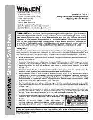
®ENGINEERING COMPANY INC.51 Winthrop RoadChester, Connecticut 06412-0684Phone: (860) 526-9504Fax: (860) 526-4078Internet: www.whelen.comSales e-mail: autosale@whelen.comCanadian Sales e-mail: autocan@whelen.comCustomer Service e-mail: custserv@whelen.comInstallation Guide:<strong>PCCHD1</strong> <strong>Switch</strong> <strong>Box</strong>Automotive: Sirens/<strong>Switch</strong>esDANGER! Sirens produces extremely loud emergency warning tones! Exposure to thesetones without proper and adequate hearing protection, could cause ear damage and/or hearingloss! The Occupational Safety & Health Administration (www.osha.gov) provides informationnecessary to determine safe exposure times in Occupational Noise Exposure Section 1910.95.Until you have determined the safe exposure times for your specific application, operators andanyone else in the immediate vicinity should be required to wear an approved hearing protectiondevice. FAILURE TO FOLLOW THIS RECOMMENDATION COULD CAUSE HEARING LOSS!Safety FirstThis document provides all the necessary information to allow your Whelen product to be properly and safely installed.Before beginning the installation and/or operation of your new product, the installation technician and operator mustread this manual completely. Important information is contained herein that could prevent serious injury or damage.• Proper installation of this product requires the installer to have a good understanding of automotive electronics,systems and procedures.• If mounting this product requires drilling holes, the installer MUST be sure that no vehicle components or othervital parts could be damaged by the drilling process. Check both sides of the mounting surface before drillingbegins. Also de-burr any holes and remove any metal shards or remnants. Install grommets into all wirepassage holes.• If this manual states that this product may be mounted with suction cups, magnets, tape or Velcro®, clean themounting surface with a 50/50 mix of isopropyl alcohol and water and dry thoroughly.• Do not install this product or route any wires in the deployment area of your air bag. Equipment mounted orlocated in the air bag deployment area will damage or reduce the effectiveness of the air bag, or become aprojectile that could cause serious personal injury or death. Refer to your vehicle owner’s manual for the air bagdeployment area. The User/Installer assumes full responsibility to determine proper mounting location, basedon providing ultimate safety to all passengers inside the vehicle.• For this product to operate at optimum efficiency, a good electrical connection to chassis ground must bemade. The recommended procedure requires the product ground wire to be connected directly to the NEGATIVE(-) battery post.• If this product uses a remote device to activate or control this product, make sure this control is located in anarea that allows both the vehicle and the control to be operated safely in any driving condition. DO NOTATTEMPT TO ACTIVATE OR CONTROL THIS DEVICE IN A HAZARDOUS DRIVING SITUATION.• It is recommended that these instructions be stored in a safe place andreferred to when performing maintenance and/or reinstallation of thisproduct.• FAILURE TO FOLLOW THESE SAFETY PRECAUTIONS ANDINSTRUCTIONS COULD RESULT IN DAMAGE TO THE PRODUCT ORVEHICLE AND/OR SERIOUS INJURY TO YOU AND YOUR PASSENGERS!ACTIVATION OF THISSIREN MAY DAMAGEUNPROTECTED EARS!WearProtection!CAUTIONLoud siren noise can causehearing damage and/or loss.Refer to OSHA Section 1910.95 priorto putting ANY siren into service!For warranty information regarding this product, visit www.whelen.com/warranty©2002 Whelen Engineering Company Inc.Form No.<strong>13718</strong>A (073007)Page 1
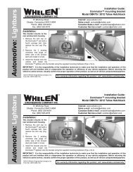
Installation:1. Position the bail strap in the selected mountinglocation. Using an awl or other suitable tool, scribe thesurface where the mounting holes are to be drilled.2. Drill the mounting holes in the areas scribed. The sizeof the drill bit should be determined by the size of themounting hardware (customer supplied) and thicknessof the mounting surface.3. Using your mounting hardware, secure bail strap tomounting location.4. With the bail strap in place, insert the carriage boltalong with the external tooth lockwasher (supplied)into the assembly hole from the inner side of the bailstrap as shown.5. Place the split lockwasher and the acorn nut on theprotruding bolt on the outer side of the bail strap.Loosely secure the acorn nut to the carriage bolt.6. Now slide the control head onto the carriage bolts.Once it is in the position that the customer has chosen,tighten the acorn nuts until the unit is firmly secured.Backlighting:10-24 ACORN NUT#10 SPLIT LOCK WASHERN0. 10 SS EXTERNAL TOOTHLOCK WASHERFUNCTION LABELS10-24 X 1/2"CARRIAGE BOLT6 Available switched outputsPLASTIC BAIL STRAPP/N 07-241559-000To + 12VDC1. Plug in the 3-position input connector and extend andconnect the BLACK wire to the vehicle’s chassisground.2. Extend the RED wire to a user supplied fuse box (3Amp fuse) and connect it to the vehicle accessoryswitch.Wiring:FUSE WIRE AT:REARVIEW25 AMPSSW625 AMPSSW525 AMPSSW425 AMPSSW325 AMPSSW225 AMPSSW1NO CONNECTION40 AMPS+BATMAXCURRENTDRAWFUNCTIONYou may control up to 6 options with a 25 Amp draw each.<strong>Switch</strong>es 1 through 6 will supply a maximum of 25 Ampseach before a switch breaker trips. The total current drawfor all 6 switches must not exceed 40 AMPS.Connect whatever options you wish to control to theterminals in the rear of the unit as shown. Follow thediagram for correct fuse sizes.TB1P1INPUTCONNECTOR1 2 3 4 5 6 7 8F140 AMPGNDLUGWARNING! All customer supplied wires thatconnect to the positive terminal of the batterymust be sized to supply at least 125% of themaximum operating current and FUSED at thebattery to carry that load. DO NOT USE CIRCUITBREAKERS WITH THIS PRODUCT!3 2 1PIN 3 - UNUSEDBLACK - GROUND18GA WIRERED - +12V18GA WIREBACK LIGHTING @ 60mA3 AMP FUSE (CUSTOMER SUPPLIED)TO VEHICLE ACCESSORY SWITCHCONNECT TO VEHICLE GROUNDPage 2