RC Circuits and The Oscilloscope - Mercer University Physics
RC Circuits and The Oscilloscope - Mercer University Physics
RC Circuits and The Oscilloscope - Mercer University Physics

Create successful ePaper yourself
Turn your PDF publications into a flip-book with our unique Google optimized e-Paper software.
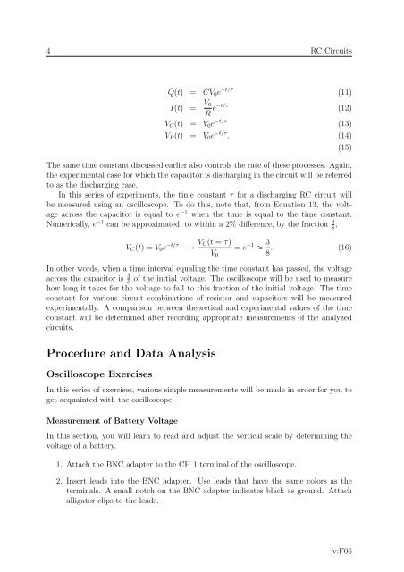
4 <strong>RC</strong> <strong>Circuits</strong>Q(t) = CV 0 e −t/τ (11)I(t) = V 0R e−t/τ (12)V C (t) = V 0 e −t/τ (13)V R (t) = V 0 e −t/τ . (14)<strong>The</strong> same time constant discussed earlier also controls the rate of these processes. Again,the experimental case for which the capacitor is discharging in the circuit will be referredto as the discharging case.In this series of experiments, the time constant τ for a discharging <strong>RC</strong> circuit willbe measured using an oscilloscope. To do this, note that, from Equation 13, the voltageacross the capacitor is equal to e −1 when the time is equal to the time constant.Numerically, e −1 can be approximated, to within a 2% difference, by the fraction 3 8 ,(15)V C (t) = V 0 e −t/τ −→ V C(t = τ)V 0= e −1 ≈ 3 8 . (16)In other words, when a time interval equaling the time constant has passed, the voltageacross the capacitor is 3 of the initial voltage. <strong>The</strong> oscilloscope will be used to measure8how long it takes for the voltage to fall to this fraction of the initial voltage. <strong>The</strong> timeconstant for various circuit combinations of resistor <strong>and</strong> capacitors will be measuredexperimentally. A comparison between theoretical <strong>and</strong> experimental values of the timeconstant will be determined after recording appropriate measurements of the analyzedcircuits.Procedure <strong>and</strong> Data Analysis<strong>Oscilloscope</strong> ExercisesIn this series of exercises, various simple measurements will be made in order for you toget acquainted with the oscilloscope.Measurement of Battery VoltageIn this section, you will learn to read <strong>and</strong> adjust the vertical scale by determining thevoltage of a battery.1. Attach the BNC adapter to the CH 1 terminal of the oscilloscope.2. Insert leads into the BNC adapter. Use leads that have the same colors as theterminals. A small notch on the BNC adapter indicates black as ground. Attachalligator clips to the leads.v:F06