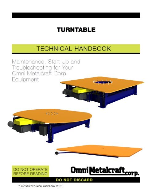
Turntable Technical Handbook.pdf - Omni Metalcraft Corp.
Turntable Technical Handbook.pdf - Omni Metalcraft Corp.
Turntable Technical Handbook.pdf - Omni Metalcraft Corp.
You also want an ePaper? Increase the reach of your titles
YUMPU automatically turns print PDFs into web optimized ePapers that Google loves.
TURNTABLE TECH HANDBOOKSAFETY INFORMATION: INSTALLATION SAFETY1) LOADING / UNLOADINGHave trained personnel load or unload equipment. The equipment must be properly handled whentransferring from the unloading area to final site location to prevent damage.2) GUARDS / GUARDINGInterfacing of Equipment. When two or more pieces of equipment are interfaced, special attention shall begiven to the interfaced area to ensure the presence of adequate guardingand safety devices.Guarding Exceptions. Wherever conditions prevail that would requireguarding under this standard but such guarding would render theequipment unusable, seek guidance from your safety professional.3) ANCHORINGDO NOT operate equipment unless it is properly anchored. Serious injury or death may result.4) SAFETY WARNINGInstall all safety devices, guards and guarding prior to equipment start-up.TURNTABLE TECHNICAL HANDBOOK 2012.16
TURNTABLE TECH HANDBOOKSAFETY INFORMATION: OPERATIONAL SAFETYOnly trained, qualified personnel shall be permitted to operate the equipment. Training shall include instructionin operation under normal conditions and emergency situations.Where safety is dependent upon stopping / starting devices, they shall be kept free of obstructions to permitaccess.The area around loading and unloading points shall be kept clear of obstructions that could endanger personnel.Do not ride the load-carrying element of a conveyor/equipmentunder any circumstances, unless the equipment is designed andequipped with safety and control devices intended to carrypersonnel. For no reason shall a person ride any element of avertical conveyor. Warning labels reading “DO NOT RIDECONVEYOR” shall be affixed by the owner of the equipment.Personnel working on or near a conveyor/equipment shall be instructed as to the location and operation ofpertinent stopping devices.Equipment shall be used to transport only a load that it is designed to handle safely.Under no circumstances shall the safety characteristics of the equipment be altered.Routine inspections and preventative and corrective maintenance programs shall be conducted to ensurethat all safety features and guards are retained and function properly. Inspect equipment for safety labels. Makesure personnel are aware of and follow safety label instructions.Alert all personnel to the potential hazard of entanglement inconveyors/equipment caused by items such as long hair, looseclothing and jewelry.SAFETY WARNINGReplace all safety devices, guards and guarding prior to equipment start-up.TURNTABLE TECHNICAL HANDBOOK 2012.18
TURNTABLE TECH HANDBOOKSAFETY INFORMATION: MAINTENANCE / SERVICE SAFETYELECTRICAL POWER MUST BE TURNED OFF AND LOCKED / TAGGED OU T followingyour company’s machine specific procedures when servicing equipment to prevent accidentalrestarting by other persons or interconnecting equipment (when used).1) MAINTENANCE (REPAIR)Maintenance and service shall be performed by trained, qualified personnel only.Where lack of maintenance and service would cause a hazardous condition, the user shall establish amaintenance program to ensure that turntable/conveyor components are maintained in a condition thatdoes not constitute a hazard to personnel.No maintenance or service shall be performed when a turntable/conveyor is in operation. See “Lubrication”and “Adjustment or Maintenance During Operation” for exceptions.When a turntable/conveyor is stopped for maintenance or service, the starting devices, prime mover,powered accessories or electrical must be locked / tagged out in accordance with a formalized proceduredesigned to protect all persons or groups involved with the turntable/conveyor against an unexpectedrestart. Personnel should be alerted to the hazard of stored energy, which may exist after the power source islocked out. All safety devices and guards shall be replaced before starting equipment for normal operation.2) ADJUSTMENT OR MAINTENANCE DURING OPERATIONWhen adjustments or maintenance must be done while equipment is in operation, only trained, qualifiedpersonnel who are aware of the hazards of the turntable/conveyor in motion shall be allowed to makeadjustments, perform maintenance or service.<strong>Turntable</strong>/conveyors shall NOT be maintained or serviced while in operation unless proper maintenance orservice requires the turntable/conveyor to be in motion. If turntable/conveyor operation is required,personnel shall be made aware of the hazards and how the task may be safely accomplished.3) LUBRICATION<strong>Turntable</strong>/conveyors shall NOT be lubricated while in operation unless it is impractical to shut them down forlubrication. Only trained and qualified personnel who are aware of the hazards of the turntable/conveyor inmotion shall be allowed to lubricate a turntable/conveyor that is operating.Where the drip of lubricants or process liquids on the floor constitutes a hazard, drip pans or other means ofeliminating the hazard must be provided by purchaser(s).4) MAINTENANCE OF GUARDS AND SAFETY DEVICESGuards and safety devices shall be maintained in a serviceable and operational condition. Warning signs arethe responsibility of the owner of the turntable/conveyor and must be maintained in a legible / operationalcondition.TURNTABLE TECHNICAL HANDBOOK 2012.19
TURNTABLE TECH HANDBOOKSAFETY INFORMATION: MAINTENANCE / SERVICE SAFETY (Continued)5) INSPECTIONSRoutine inspections with preventative and /or corrective maintenance programs shall be conducted to ensurethat all safety features and devices are maintained and function properly.All personnel shall inspect for hazardous conditions at all times. Remove sharp edges or protruding objects.Repair or replace worn or damaged parts immediately.6) CLEANINGWhere light cleaning and/or casing cleaning are required, they shall be performed by trained personnel. Theturntable/conveyor electrical power must be turned off and locked / tagged out following your company’smachine specific procedures. Special attention may be required at feed and discharge points.7) SAFETY WARNINGReplace all safety devices, guards and guarding prior to equipment start-up.TURNTABLE TECHNICAL HANDBOOK 2012.110
TURNTABLE TECH HANDBOOKRECEIVING AND INSPECTION: RETURNS, DAMAGES AND SHORTAGESUNCRATING CHECKLIST1) Compare the bill of lading with what you have received (including accessories).2) Examine the equipment for damage.3) Immediately report shortages or damages to the vendor and carrier.4) Obtain a signed damage report from the carrier and send a copy to the vendor.Do not attempt to modify or repair damaged equipment prior to filing this report.Note:Do not return equipment to the factory without a written return authorization. Returns without writtenauthorization will not be accepted.Note: Custom products may be crated differently.MOTOR DRIVEN ROLLER CONVEYOR STRAIGHT AND CURVE TECH HANDBOOKRECEIVING AND INSPECTION: REMOVAL OF CRATINGAFTER COMPLETING THE “UNCRATING CHECKLIST”1) Remove crating and packaging.2) Look for boxes, accessories, bags or components such as fasteners, manuals, guard rails etc. that may bebanded or fastened to the crating material.Note: Make sure all fasteners, guards and essential components are not discarded.TURNTABLE TECHNICAL HANDBOOK 2012.111
TURNTABLE TECH HANDBOOKGENERAL INSTALLATION: INSTALLATION INSTRUCTIONS1) <strong>Turntable</strong>s are shipped on either skids or pallets. With slings placed around the base frame, remove the unitfrom the skid. Be careful not to damage any of the frame structure. DO NOT LIFT THE UNIT BY THE TOPPLATE OR ANY ATTACHED EQUIPMENT!2) Position the unit keeping the entire “swing diameter” clear. (If equipped with mounted conveyor, checkconveyor alignment with stationary conveyors.)3) For turntables with legs, see the “Leg Supports and Installation” page for leg adjustment procedure.4) Instruct user(s) in the proper operation of the turntable, safety precautions and equipment capacity. Supplymaintenance personnel with this service manual.TURNTABLE TECHNICAL HANDBOOK 2012.112
TURNTABLE TECH HANDBOOKGENERAL INSTALLATION: OPERATING INSTRUCTIONSPREOPERATIONAL CHECKS1) Check all electrical wiring and connections to be sure that they are completed properly and are operational.2) Check for obstructions or debris within the “swing-diameter” that may interfere with the safe operation ofthe turntable.3) Be sure that all personnel in the area are a safe distance away from the unit and aware that you are about tooperate it.4) If there are any optional safety devices such as bellows or electric toe guards, check them for properoperation.TEST OPERATE THE EQUIPMENT1) Station yourself so that you will always see the equipment when it is in operation.2) Cycle the equipment several times to be sure that it is operating smoothly with no jerking or suddenmovement.3) Test the rotation time of the unit while fully loaded to ensure that the torque limiter is functioning properly.4) Check all safety devices for proper operation.TURNTABLE TECHNICAL HANDBOOK 2012.113
TURNTABLE TECH HANDBOOKLEG SUPPORTS AND INSTALLATIONWELDED LEG ADJUSTMENTSNote:Only qualified installation professionals shouldlevel and install conveyor.WELDED LEG ADJUSTMENT: JACK-BOLT1) The conveyor electrical power must be turned off and locked /tagged out following your company’s machine specificprocedures.2) Remove all load from the conveyor.3) Position conveyor in the location to be installed.4) Support conveyor section with jack, hoist or forklift.5) Carefully loosen the retaining bolt.6) Carefully loosen the jam nut holding the jack-bolt in position onthe jack-bolt plate.7) Adjust the boot position by turning the jack-bolt.8) Ensure that the conveyor is completely level. (reference levelingnote above)9) Tighten the jam nut securely against the jack-bolt plate usingtorque appropriate for each fastener’s size and grade.(grade 5 fasteners provided)LEG BOOT10) Tighten the retaining bolt using torque appropriate for eachfastener’s size and grade. (grade 5 fasteners provided)WELDED LEG ADJUSTMENT: NON-JACK-BOLT1) The conveyor electrical power must be turned off and locked /tagged out following your company’s machine specificprocedures.2) Remove all load from the conveyor.3) Position conveyor in the location to be installed.4) Support conveyor section with jack, hoist or forklift.5) Carefully loosen the retaining bolt.6) Lift or lower conveyor until it is at the desired height.7) Ensure that the conveyor is completely level. (reference levelingnote above)8) Tighten fasteners using torque appropriate for each fastener’ssize and grade. (grade 5 fasteners provided)9) Secure the leg boot to the upright by either of the methodslisted below:LEG BOOTA) Weld the boot into place.B) Drill through boot and upright and bolt the boot securelyinto place.BASEUPRIGHTJACK-BOLTJAM NUTJACK-BOLT PLATESPREADERFOOT TOP PLATERETAINING BOLTFOOT PADBASEUPRIGHTSPREADERRETAINING BOLTFOOT PADTURNTABLE TECHNICAL HANDBOOK 2012.114
TURNTABLE TECH HANDBOOKOPTIONAL EQUIPMENT: TORQUE LIMITERSTorque limiters protect machinery from damage due to unexpected overload conditions. The driven centermember slips on nonasbestos friction discs during extraordinary loads on the driveline. Torque limitersautomatically reset when the overload condition is relieved.MODELS 250 AND 350 (350 MODEL SHOWN)MODELS 500 AND 700 (500 MODEL SHOWN)ACBDPRESSUREPLATEDBCASET SCREWHUBADJUSTING NUTLOCK WASHERSPRINGFRICTIONDISCBUSHINGFRICTIONDISCADJUSTING NUTSPRING RETAINERSPRINGModelTorque Ratings (lb - ft)One SpringTwo SpringsMin. Max. Min. Max.250 25 60 30 95350 50 120 60 190500 90 250 120 400700 200 620 290 900ABDimensions (inches)Min.CMax.DWeight(lbs)2 1/2 1 3/4 1/8 11/32 5/8 13 1/2 2 3/16 1/8 1/2 3/4 25 2 7/8 1/4 5/8 7/8 77 3 7/8 7/16 3/4 1 17TORQUE RATINGSThe torque ratings are estimates that may be used as a basis for selection and comparison to other products.Actual torque capacity may vary significantly depending upon many factors.The center drive member must be flat and parallel with a proper bore size as described on page 18. The torquelimiter should be installed and “run-in” per instructions provided with each shipment.Field conditions such as oil, humidity, water and temperature, as well as the frequency and duration of slippagewill affect torque capacity.BORE SIZESTorque limiters have hubs with a wide range of finished bore sizes that are provided with USA standard keywaysand one set screw. Hubs with a minimum plain bore are available for each model. Special metric bores andkeyways per ISO standard are available upon request.RESTRICTIONS ON USETorque Limiters were not designed to function as clutches and must not be used to engage or disengage drivesystems. They should never be use as personal protection devices. They are best suited for low speed mechanicaldrive where slippage is infrequent and of short duration.TURNTABLE TECHNICAL HANDBOOK 2012.115
TURNTABLE TECH HANDBOOKOPTIONAL EQUIPMENT: TORQUE LIMITERSTORQUE LIMITER INSTALLATION AND TORQUE ADJUSTMENT INSTRUCTIONSMODELS 500 AND 700 (500 MODEL SHOWN)BAPRESSUREPLATESET SCREWDCHUBADJUSTINGNUT SCREWSADJUSTING NUTFRICTION DISCBUSHINGSPRING RETAINERSPRINGINSTALLATION1) In addition to the torque limiter, obtain a center member, usually a sprocket. Ensure that it is finishedaccording to the specifications shown in the literature. Select a bushing to fit the bore and width of thecenter member.2) Back off the three adjusting nut screws four full turns.3) Remove the adjusting nut, spring retainer, spring, pressure plate and one friction disc.4) Ensure that the friction discs are free of oil or moisture.5) Install the bushing over the hub and pilot the center member over the bushing. Re-assemble the friction disc,pressure plate with the smooth side to the friction disc, spring, spring retainer with pilot facing the springand the adjusting nut.6) Advance the adjusting nut to a finger–tight position, ensuring that the spring is piloted on the spring retainer.RUN IN PROCEDURE1) It is recommended that the unit be “run in” by slipping the center member.2) Ensure that the three adjusting nut screws are backed off four turns and that the adjusting nut is in a fingertightposition.3) Match mark the adjusting nut and hub. Back off the adjusting nut 1 1/2 turns for the 500 model or 2 1/4turns for the 700 model. Tighten the three adjusting nut screws alternately until the heads bottom.4) Slip the center member for 3 to 4 minutes at approximately 50 RPM.5) Install the torque limiter on the shaft with a key and tighten the set screw in the hub.TURNTABLE TECHNICAL HANDBOOK 2012.116
TURNTABLE TECH HANDBOOKOPTIONAL EQUIPMENT: TORQUE LIMITERSTO ADJUST TORQUE1) Ensure that the three adjusting nut screws are backed off four full turns and that the adjusting nut is in afinger-tight position.2) Match mark the adjusting nut with the hub. Back off the adjusting nut the number of turns that correspondto the desired break away torque as shown in the chart below.Model5001 Spring5002 SpringsApproximate Break Away Torque90 lb ft 150 lb ft 200 lb ft120 lb ft 300 lb ft 350 lb ft3) Tighten the three adjusting screws alternately until the heads bottom.250 lb ftmax400 lb ftmaxTurns 1 1/2 1 3/4 07001 Spring7002 Springs300 lb ft 400 lb ft 530 lb ft450 lb ft 600 lb ft 750 lb ft620 lb ftmax900 lb ftmaxTurns 2 1 3/4 1 1/4 0TURNTABLE TECHNICAL HANDBOOK 2012.117
TURNTABLE TECH HANDBOOKOPTIONAL EQUIPMENT: ADDITIONAL OPTIONSLIMIT SWITCHES OR PROXIMITY SWITCHESTo determine position of table topAcceleration or deceleration timingSLIP RINGRoute power through center of table to rotating deck of turntableMay affect the minimum height of tableROTARY UNIONRoute air or hydraulic oil to rotating deck of turntableRotary unions may affect the minimum height of table250 PSI maximumMOTOR OPTIONSInverter duty motor, air motor, hydraulic motorGRAVITY TRANSITION ROLLERSGravity transition rollers are standard on units that incorporate a conveyor deckGravity transition rollers, which are attached to the rotating part of the turntable, are used to assist insupporting products during the transition from adjoining conveyor to the turntablePowered transition rollers are also available to aid problem productsFixed transition rollers can also be mounted to adjoining conveyor or turntable baseDETENTSSpring/non-lockingLocking StyleHand releaseFoot releaseCustom options availableTURNTABLE TECHNICAL HANDBOOK 2012.118
TURNTABLE TECH HANDBOOKPRE-START-UP OVERVIEW: PREPARING FOR INITIAL START-UP1) Review pages 7 and 8 prior to starting any equipment.2) Verify that conveyor sections, leg supports, etc. were installed properly.3) Verify that all roller-to-roller and drive chains and sprockets are installed, aligned, and tensioned properly.4) Verify that set screws are fastened securely in sprockets, bearings, etc.5) Check all fastening hardware. Tighten securely.6) Verify that all motor control wiring is connected properly.7) Verify that conveyor is not loaded with product.8) Verify that gearboxes are filled with the proper amount of oil or that they were factory filled with lube. (Ifyour turntable/conveyor is equipped with a Boston 700 Series Reducer, it is filled with oil, sealed and lubedfor life thus requiring no oil changes. Literature provided with equipment will give detailed gearbox lube info)9) Verify that the gearbox has necessary vent plugs installed if applicable. (If your turntable/conveyor isequipped with a Boston 700 Series Reducer, it is supplied with a PosiVent® and no vent plug is required.Literature provided with equipment will give detailed info on gearbox vent plug requirements.)10) Non Jack-Bolt leg boots are to be welded to leg uprights or bolted in place prior to introduction of productloads. See page 15.TURNTABLE TECHNICAL HANDBOOK 2012.119
TURNTABLE TECH HANDBOOKPRE-START-UP OVERVIEW: DRIVE CHAIN AND SPROCKET ALIGNMENTDRIVE CHAIN AND SPROCKET ALIGNMENTTo achieve maximum service life and efficiency from a chain drive, follow these simple guidelines:Visually inspect the roller chain, sprockets, and other components and verify that they are in good condition.Ensure that the sprockets are properly aligned.Adequately lubricate the chain.Inspect for proper chain tension.CONDITION OF COMPONENTSShafting and bearings should be supported rigidly to maintain the initial alignment.Roller chain should be free of grit and dirt. Wash chain in kerosene when required. Relubricate.DRIVE ALIGNMENTMisalignment results in uneven loading across the width of the chain and may cause roller link-plate and sprockettooth wear. Drive alignment involves two things: parallel shaft alignment and axial sprocket alignment.ALIGNING SHAFTSShafts should be parallel and level. If there is axial movement of the shaft (as in the case of an electric motor),lock the shaft in the normal running position before aligning the sprockets.ALIGNING SPROCKETSSprocket axial alignment can be checked with a straight edge which will extend across the finished sides of thetwo sprockets. Normally, it is good practice to align the sprockets as close to the shaft bearing as possible. Forlong center distances, use a taut cord, or wire long enough to extend beyond each of the sprockets.SPROCKETSTRAIGHT EDGESET SCREWSSPROCKETWARNING:Before performing anymaintenance, lubrication orinspection on any poweredturntable/conveyor, theelectrical power must beturned off and locked /tagged out following yourcompany’s machine specificprocedure. NEVER operatethe turntable/conveyor withany guard removed.TURNTABLE TECHNICAL HANDBOOK 2012.120
TURNTABLE TECH HANDBOOKPRE-START-UP OVERVIEW: DRIVE CHAIN AND SPROCKET TENSIONINSTALLING THE CHAINRecheck all preceding adjustments for alignment and make certain all setscrews, bolts and nuts are tight. Fitchain around both sprockets and bring the free ends together on one sprocket for connection. The sprocket teethwill locate the chain end links. Install the connecting link, connecting link cover plate and the spring clip or cotterpins. On larger pitch chains or heavy multiple strand, it may be necessary to lock the sprockets for this operation.CHAIN TENSIONCheck chain tension to be certain the slack span has an approximate 2% mid-span movement.CHAIN TOO TIGHTCHAIN TOO LOOSECORRECT SLACKSPROCKET CENTERSRequires extra power andcauses excessive wearCauses excessive wear andexcessive noiseApproximately 2% ofsprocket centersCHAIN DRIVEN LIVE ROLLER CONVEYOR STRAIGHT AND CURVE TECH HANDBOOKPRE-START-UP OVERVIEW: GEAR REDUCER VENT PLUGPosiVent®<strong>Omni</strong> <strong>Metalcraft</strong> <strong>Corp</strong>. standardly suppliesthe Boston Gear PosiVent® option for allcurrent 700 series styles and configurations.This specially-designed internal pressureequalization system allows the gearbox tooperate in all environments without the useof conventional pressure vents. The uniquedesign comes complete with Klubersynth UH16-460 lubrication pre-filled for all mountingpositions. Unlike competitive versions, thisunique single seam design allows for easyinstallation and extended life. This meanslonger trouble-free operation with virtuallyno maintenance.TURNTABLE TECHNICAL HANDBOOK 2012.121
TURNTABLE TECH HANDBOOKPRE-START-UP OVERVIEW: INSPECTION AND LUBRICATIONCARE AND MAINTENANCE OF CHAINProper maintenance of any chain should include correct lubrication, periodic inspection and proper adjustmentfor normal wear. Periodic inspection of the chain and sprockets is required to detect any deviation from normalwear before serious damage takes place. The cost of such inspection is repaid many times in extended chain lifeand in freedom from failure. No general rule can be given for the frequency of inspection. The frequency shouldbe influenced by conditions of operation.CHAIN LUBRICATION AND ENVIRONMENTOne of the most important factors in getting the best possible performanceout of our drive chain is proper lubrication. A well lubricated chain will havean operating life much longer than that of an unlubricated chain. Wearbetween the pin and bushing causes drive chain to elongate. These partsshould, therefore, be well lubricated. The gap between the roller link plateand the pin link plate on the slack side of the chain should be filled with oil.This oil forms a film which minimizes wear on the pin and bushing, thusincreasing the chain’s service life. It also reduces noise and acts as a coolantwhen the chain runs at high speeds.PIN LINK PLATEClean Atmosphere: Chains operating in a relatively clean atmosphere can be lubricated by brush or dripfeedoilers or by applying the lubricant manually with a brush or oil can.Atmosphere with Lint or Non-Abrasive Dust: Where large volumes of lint or non-abrasive dust arepresent, a brush or wiper can be used to clean the chain and apply a lubricant. Otherwise the lint or dustwill clog the chain joint clearance and prevent penetration of the oil into the joints.Abrasive Atmosphere: If abrasives come in contact with chain, lubrication becomes more difficult. Whenlubricants are applied externally, abrasive particles tend to adhere to the chain surfaces and act as alapping or grinding compound. Under extreme conditions it is sometimes advisable to avoid chainlubrication.Extreme Conditions: Consult a lubricant manufacturer when chains are required to operate attemperatures outside of those indicated in the chart below or if chains are used in other extremeconditions.SUGGESTED LUBRICATIONOnly high quality oil should be used to lubricate chain. Neither heavy oil nor grease is suitable. The lubricantshould have a viscosity to enable it to reach internal surfaces under normal conditions. Lubricants suggested forspecific ambient temperatures and chain speed ranges are given in the table below.TEMPERATURECHAIN NUMBER 15° - 35° F 35° - 105° F 105° - 120° F 120° - 140° FANSI 25 - 50 SAE10W SAE20 SAE30 SAE40ANSI 60 - 100 SAE20 SAE30 SAE40 SAE50ANSI 120 - 240 SAE30 SAE40 SAE504" & 6" PITCH(ENGINEERED CHAIN)SAE20 SAE30 SAE40PINROLLERROLLER LINK PLATEBUSHINGTURNTABLE TECHNICAL HANDBOOK 2012.122
TURNTABLE TECH HANDBOOKMAINTENANCE: MAINTENANCE SCHEDULESNote:Review pages 9 and 10 prior to maintaining any equipment.If equipment repair or replacement is required during inspections, thoroughly review the manufacturer’s specificproduct information for correct procedure.DAILY MAINTENANCEInspect turntable to ensure that all guarding is securely in place.WEEKLY MAINTENANCEInspect turntable for loose bolts and set screws.Inspect turntable for unusual or excessive noise or heat in bearings, reducers and motors.Inspect turntable drive chain to ensure that it runs freely and without excessive noise.MONTHLY MAINTENANCEInspect reducers for leaks around seals. If required, check lubrication for proper level or amount.Inspect drive chains and sprockets for wear, alignment and proper chain tension. Inspect all other chains andsprockets for wear and lubricate. For chain lubrication information see page 23. When lubricating drive chaincare must be taken not to allow lubricant to come in contact with torque limiter friction disk pads.Grease all roller turn rollers, center bearing and/or rotary bearings. Use a No. 2 lithium grease or equivalent.Brush grease on roller turn roller path after initial break in (1/4 - 1/2” wide groove worn into roller path).Use a No. 2 lithium grease or equivalent.ANNUAL MAINTENANCEChange oil in reducers. (If your turntable is equipped with a Boston 700 Series Reducer, it is filled with oil,sealed and lubed for life thus requiring no oil changes. See manufacturer’s information for recommendedlubricant at specific temperatures. This information is shipped with every reducer.)TURNTABLE TECHNICAL HANDBOOK 2012.123
TURNTABLE TECH HANDBOOKMAINTENANCE: REPORT ON MISCELLANEOUS MAINTENANCE PERFORMANCEREPORT ON MISCELLANEOUS MAINTENANCE PERFORMANCEDate___________Maintenance Performed:____________________________________________________________________________________________________________________________________________________________________________________________________________________________________________________________________________________Date___________Maintenance Performed:____________________________________________________________________________________________________________________________________________________________________________________________________________________________________________________________________________________Date___________Maintenance Performed:____________________________________________________________________________________________________________________________________________________________________________________________________________________________________________________________________________________Date___________Maintenance Performed:____________________________________________________________________________________________________________________________________________________________________________________________________________________________________________________________________________________Date___________Maintenance Performed:____________________________________________________________________________________________________________________________________________________________________________________________________________________________________________________________________________________Date___________Maintenance Performed:____________________________________________________________________________________________________________________________________________________________________________________________________________________________________________________________________________________Date___________Maintenance Performed:____________________________________________________________________________________________________________________________________________________________________________________________________________________________________________________________________________________TURNTABLE TECHNICAL HANDBOOK 2012.124
TURNTABLE TECH HANDBOOKTROUBLESHOOTING AND REPLACEMENT PARTS: TROUBLESHOOTINGPROBLEM CAUSE SOLUTION<strong>Turntable</strong> does not start, rotate ormotor stalls frequentlyMotor is overloadedTorque limiter not setMotor is drawing excessive currentCheck for turntable overloadSet torque limiter per TorqueLimiter instructions on page 16.Check circuit breakerExcessive drive chain and/orsprocket wearLoud popping/grinding noiseOverheating motor and/orreducerInsufficient lubricationMisaligned sprocketsLoose drive chainExcessive chain tensionDefective bearingLoose set screw on drive sprocketImproperly tensioned drive chainRoller turn roller misalignmentInsufficiently greased roller turn rolleror pathDamaged roller turn roller supportbracketOverloaded conveyorLow voltage to motorInsufficient reducer lubrication levelBrake motor or independently wiredbrake not releasingLubricate chainTension drive chain properly andalign drive sprocketsReplace bearingCheck key and tighten set screw ondrive sprocketTension drive chain and align drivesprocketsAlign roller turn roller axle withcenter line of tableGrease roller turn roller bearingsand/or pathReplace roller turn roller supportbracketCheck for conveyor overloadApply proper voltageFill reducer lubricant reservoir ifapplicableCheck for proper installation and/or wiring to brake motor orindependently wired brake.TURNTABLE TECHNICAL HANDBOOK 2012.125
TURNTABLE TECH HANDBOOKPARTS LISTS: LOW PROFILE MANUAL TURNTABLE (LPMT)DETAILDESCRIPTION1 TOP PLATE WELDMENT2 TURNTABLE BASE WELDMENT3 SLEEVE BEARING4 CAM FOLLOWER5 DETENT6 HEX HEAD CAP SCREW7 FLAT WASHER8 LOCK WASHER9 HEX NUTTURNTABLE TECHNICAL HANDBOOK 2012.126
TURNTABLE TECH HANDBOOKPARTS LISTS: ROLLER TURN ROLLER TURNTABLEDETAIL DESCRIPTION DETAIL DESCRIPTION1 TURN TABLE BASE WELDMENT 16 MOTOR2 TOP PLATE WELDMENT 17 DRIVE GUARD3 ROLLER SUPPORT WELDMENT 18 REDUCER4 ROLLER TURN ROLLER 19 REDUCER MOUNTING PLATE5 ROLLER BOLT (REGREASEABLE) 20 FOOT WELDMENT6 BEARING 21 LIMIT SWITCH ASSEMBLY7 SPACER RING 22 LIMIT SWITCH TRIGGER8 IDLER SPROCKET 23 J-BOX BRACKET9 CHAIN GUIDE 24 SLIP RING ANTI-ROTATION BRACKET10 WEAR STRIP 25 PIPE NIPPLE11 LEFT CORNER CLAMP 26 JAM NUT12 RIGHT CORNER CLAMP 27 HEX HEAD CAP SCREW13 TORQUE LIMITER 28 LOCK WASHER14 DRIVE SPROCKET 29 JAM NUT15 ROLLER CHAIN 30 HEX NUT27TURNTABLE TECHNICAL HANDBOOK 2012.1
TURNTABLE TECH HANDBOOKPARTS LISTS: ROTARY BEARING TURNTABLEDETAIL DESCRIPTION DETAIL DESCRIPTION1 TURN TABLE BASE WELDMENT 15 BOTTOM CHAIN GUARD2 TOP PLATE WELDMENT 16 TOP CHAIN GUARD3 YOKE ROLLER ASSEMBLY (OPTIONAL) 17 WEAR STRIP4 CHAIN GUIDE WELDMENT 18 RIGHT CORNER CLAMP5 BEARING (ROTARY) 19 LEFT CORNER CLAMP6 IDLER SPROCKET 20 BUMPER BRACKET WELDMENT7 FOOT WELDMENT 21 RUBBER BUMPER8 REDUCER PLATE 22 PROX BRACKET9 TORQUE LIMITER 23 SPACER10 DRIVE SPROCKET 24 SHIM11 ROLLER CHAIN 25 HEX HEAD CAP SCREW12 REDUCER 26 LOCK WASHER13 BRAKE 27 HEX NUT14 MOTOR28TURNTABLE TECHNICAL HANDBOOK 2012.1
TURNTABLE TECH HANDBOOKNOTESNotes:____________________________________________________________________________________________________________________________________________________________________________________________________________________________________________________________________________________________________________________________________________________________________________________________________________________________________________________________________________________________________________________________________________________________________________________________________________________________________________________________________________________________________________________________________________________________________________________________________________________________________________________________________________________________________________________________________________________________________________________________________________________________________________________________________________________________________________________________________________________________________________________________________________________________________________________________________________________________________________________________________________________________________________________________________________________________________________________________________________________________________________________________________________________________________________________________________________________________________________________________________________________________________________________________________________________________________________________________________________________________________________________________________________________________________________TURNTABLE TECHNICAL HANDBOOK 2012.129
TURNTABLE TECH HANDBOOKABBREVIATED WARRANTY<strong>Omni</strong> <strong>Metalcraft</strong> <strong>Corp</strong>. warrants that the Equipment will be free of defects in workmanship and material (ifproperly installed, operated and maintained) for a period of one year or 2080 hours of use, whichever is sooner,from date of shipment to Customer, subject to the limitations hereunder set forth. If within the one yearwarranty period, <strong>Omni</strong> receives from the Customer written notice of any alleged defects in the Equipment and ifthe Equipment is not found to be in conformity with this warranty (the Customer having provided <strong>Omni</strong> areasonable opportunity to perform any appropriate tests thereon) <strong>Omni</strong> will, at its option, either repair theEquipment or supply a replacement therefore.*The above stated information is in reference to a section of <strong>Omni</strong> <strong>Metalcraft</strong>’s full Terms and Conditions of sale. This information does notconstitute an agreement, but simply reference information. To obtain a full copy of <strong>Omni</strong> <strong>Metalcraft</strong>’s Terms and Conditions of sale, pleasecontact your sales representative.TURNTABLE TECHNICAL HANDBOOK 2012.130
TURNTABLE TECHNICAL HANDBOOK 2012.131


