G-1582BI:G1582tri rev B.qxd.qxd - Varian
G-1582BI:G1582tri rev B.qxd.qxd - Varian
G-1582BI:G1582tri rev B.qxd.qxd - Varian

You also want an ePaper? Increase the reach of your titles
YUMPU automatically turns print PDFs into web optimized ePapers that Google loves.
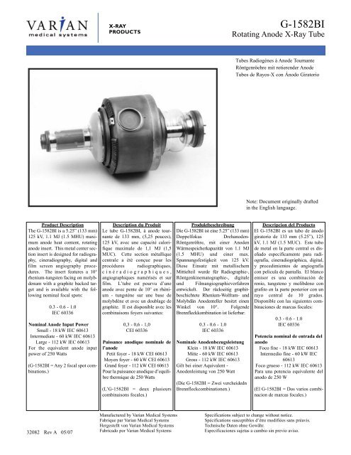
Product Description<br />
The G-<strong>1582BI</strong> is a 5.25” (133 mm)<br />
125 kV, 1.1 MJ (1.5 MHU) maximum<br />
anode heat content, rotating<br />
anode insert. This metal center section<br />
insert is designed for radiography,<br />
cineradiography, digital and<br />
film screen angiography procedures.<br />
The insert features a 10°<br />
rhenium-tungsten facing on molybdenum<br />
with a graphite backed target<br />
and is available with the following<br />
nominal focal spots:<br />
0.3 - 0.6 - 1.0<br />
IEC 60336<br />
Nominal Anode Input Power<br />
Small - 18 kW IEC 60613<br />
Intermediate - 60 kW IEC 60613<br />
Large - 112 kW IEC 60613<br />
For the equivalent anode input<br />
power of 250 Watts<br />
(G-<strong>1582BI</strong> = Any 2 focal spot combinations.)<br />
32082 Rev A 05/07<br />
X-RAY<br />
PRODUCTS<br />
Description du Produit<br />
Le tube G-<strong>1582BI</strong>, à anode tournante<br />
de 133 mm, (5,25 pouces),<br />
125 kV, avec une capacité calorifique<br />
maximale de 1,1 MJ (1,5<br />
MUC). Cette section métallique<br />
centrale a été conçue pour les<br />
procédures radiographiques,<br />
cinéradiographiques,<br />
angiographiques numérisés et sur<br />
film. L’tube est pourvu d’une<br />
anode avec pente de 10° en rhènium<br />
- tungsténe sur une base de<br />
molybdéne et avec un doublage de<br />
graphite. Il est disponible avec les<br />
combinaisons foyers suivantes:<br />
0,3 - 0,6 - 1,0<br />
CEI 60336<br />
Puissance anodique nominale de<br />
l’anode<br />
Petit foyer - 18 kW CEI 60613<br />
Moyen foyer - 60 kW CEI 60613<br />
Grand foyer - 112 kW CEI 60613<br />
Pour la puissance anodique d’equilibre<br />
thermique de 250 Watts<br />
(L’G-<strong>1582BI</strong> = deux plusieurs<br />
combinaisons focales.)<br />
Manufactured by <strong>Varian</strong> Medical Systems<br />
Fabrique par <strong>Varian</strong> Medical Systems<br />
Hergestellt von <strong>Varian</strong> Medical Systems<br />
Fabricado por <strong>Varian</strong> Medical Systems<br />
Produktbeschreibung<br />
Die G-<strong>1582BI</strong> ist eine 5.25” (133 mm)<br />
Doppelfokus Drehanoden-<br />
Röntgenröhre, mit einer Anoden<br />
Wärmespeicherkapazität von 1.1 MJ<br />
(1.5 MHU) und einer max.<br />
Spannungsfestigkeit von 125 kV.<br />
Diese Einsatz mit metallischem<br />
Mittielteil wurde für Radiographie-,<br />
Röntgenkinematographie-, digitale<br />
und Filmangiographieverfahren<br />
entwickelt. Der rückseitig graphitbeschichtete<br />
Rhenium-Wolfram- und<br />
Molybdän Anodenteller besitzt einen<br />
Winkel von 10°. Folgende<br />
Brennfleckkombination ist lieferbar:<br />
0.3 - 0.6 - 1.0<br />
IEC 60336<br />
Nominale Anodenbezugsleistung<br />
Klein - 18 kW IEC 60613<br />
Mitte - 60 kW IEC 60613<br />
Gross - 112 kW IEC 60613<br />
Gilt bei einer Aquivalent -<br />
Anodenleistung von 250 Watt<br />
(Die G-<strong>1582BI</strong> = Zwei vercheidedn<br />
Brennfleckcombinationen.)<br />
G-<strong>1582BI</strong><br />
Rotating Anode X-Ray Tube<br />
Tubes Radiogénes à Anode Tournante<br />
Röntgenröehre mit rotierender Anode<br />
Tubos de Rayos-X con Ánodo Giratorio<br />
Note: Document originally drafted<br />
in the English language.<br />
Descripcion del Producto<br />
El G-<strong>1582BI</strong> es un tubo de ánodo<br />
giratorio de 133 mm (5.25”), 125<br />
kV, 1.1 MJ (1.5 MUC). Este tubo<br />
de metal en la parte central es diseñado<br />
especificamente para radiografía,<br />
cineradiográphica, digital,<br />
y procedimientos de angiografía<br />
con pelicula de pantalla. El blanco<br />
emisor es una combinación de<br />
renio, tungsteno y molibdeno con<br />
grafito en la parte posterior con un<br />
rayo central de 10 grados.<br />
Disponible con las siguientes combinaciones<br />
de marcas focales:<br />
0.3 - 0.6 - 1.0<br />
IEC 60336<br />
Potencia nominal de entrada del<br />
anodo<br />
Foco fine - 18 kW IEC 60613<br />
Intermedio fine - 60 kW IEC<br />
60613<br />
Foco grueso - 112 kW IEC 60613<br />
Para una potencia equivalente del<br />
anodo de 250 W<br />
(El G-<strong>1582BI</strong> = Dos varios combinacion<br />
de marcas focales.)<br />
Specifications subject to change without notice.<br />
Spécifications susceptibles d’être modifiées sans préavis.<br />
Technische Daten ohne Gewähr.<br />
Especificaciones sujetas a cambio sin p<strong>rev</strong>io aviso.
Small -White<br />
Petit - Blanc<br />
Klein - Weiss<br />
Pequeño - Blanco<br />
Intermediate<br />
Moyen<br />
Mitte<br />
Intermedio<br />
X-RAY<br />
PRODUCTS<br />
Large - Black<br />
Grand - Noir<br />
Gross - Schwarz<br />
Largo - Negro<br />
Common - Red<br />
Neutre - Rouge<br />
Neutral - Rot<br />
Común - Rojo<br />
Copyright © 2007, <strong>Varian</strong> Medical Systems. All Rights Reserved.<br />
2<br />
Stand - By<br />
Attente<br />
Bereitschaft<br />
En Espera<br />
Frame or Chasis<br />
Masse<br />
Chassis<br />
Soporte o Chasis<br />
G-<strong>1582BI</strong><br />
Tube Outline Drawing<br />
Dessin d’Encombrement de la Tube<br />
Maßzeichnungen des Drehanoden-Röntgenröhre<br />
Esquema Detallado del Tubos<br />
X-Ray Tube<br />
Tube Radiogène<br />
Röntgenröhre<br />
Tubo de Rayos X<br />
Radiation Filter or Filtration<br />
Filtre de rayonnement<br />
Filterung<br />
Filtración de Radiación
X-RAY<br />
PRODUCTS<br />
Copyright © 2007, <strong>Varian</strong> Medical Systems. All Rights Reserved.<br />
3<br />
G-<strong>1582BI</strong><br />
Filament Emission Charts IEC 60613<br />
Abaques d’ Émissions des Filaments CEI 60613 Heizfadenemissionsdiagramm IEC 60613 Curvas de Emisión de los Filamentos IEC 60613<br />
THREE PHASE EMISSION (± .15 A)<br />
G-<strong>1582BI</strong> 0.3<br />
3 Ø FULL WAVE<br />
THREE PHASE EMISSION (± .15 A)<br />
G-<strong>1582BI</strong> 1.0<br />
THREE PHASE EMISSION (± .15 A)<br />
G-<strong>1582BI</strong> 0.6<br />
Note: When using these emission curves for trial exposures, refer to the power rating curves shown for maximum kV, tube emission, filament<br />
current, exposure time, and target speed.<br />
Remarque: Lors de l’utilisation de ces abaques pour des expositions d’essai, référez-vous aux courbes maximales de kV, d’émission du filament, de temps<br />
d’exposition et de vitesse de rotation.<br />
Anmerkung: Wenn Sie diese Emissionskurven für Testaufnahmen verwenden, beziehen Sie sich hierbei auf die entsprechenden Nennleistungskurven für<br />
max. kV-Werte, Röhrenemission, Heizstrom, und Anodendrehzahl.<br />
Nota: Si utiliza estas curvas de emisión para exposiciones de prueba, refiérase a las curvas de gradación de potencia para el máximo de kV, tubo de<br />
emisión, corriente en los filamentos, tiempo de exposión, y a las curvas de velocidad del objetivo.
X-RAY<br />
PRODUCTS<br />
Copyright © 2007, <strong>Varian</strong> Medical Systems. All Rights Reserved.<br />
4<br />
G-<strong>1582BI</strong><br />
Single Load Ratings IEC 60613<br />
Abaques de Chargepour Pose Unique CEI 60613 Brennfleck Belastungskurven IEC 60613 Diagramas de Exposición Radiográfica IEC 60613<br />
Nominal anode input power for the anode<br />
heat content 40%. IEC 60613<br />
50 HZ 3 Ø Constant Potential<br />
Puissance calorifique nominale de l’anode:<br />
40%, CEI 60613<br />
Thermische Anodenbezugsleistung bei<br />
einer Wärmespeicherung von 40%. IEC<br />
60613<br />
60 HZ<br />
Aproximadamente el poder de penetracion<br />
para obtener un almacenaje de calor del<br />
anodo de 40%. IEC 60613
X-RAY<br />
PRODUCTS<br />
Abaques de Chargepour Pose Unique CEI 60613 Brennfleck Belastungskurven IEC 60613 Diagramas de Exposición Radiográfica IEC 60613<br />
Nominal anode input power for the anode<br />
heat content 40%. IEC 60613<br />
150 HZ 3 Ø Constant Potential<br />
Puissance calorifique nominale de l’anode:<br />
40%, CEI 60613<br />
Copyright © 2007, <strong>Varian</strong> Medical Systems. All Rights Reserved.<br />
5<br />
Thermische Anodenbezugsleistung bei<br />
einerWärme speicherung von 40%. IEC<br />
60613<br />
G-<strong>1582BI</strong><br />
Single Load Ratings IEC 60613<br />
180 HZ<br />
Aproximadamente el poder de penetracion<br />
para obtener un almacenaje de calor del<br />
anodo de 40%. IEC 60613
X-RAY<br />
PRODUCTS<br />
CINERADIOGRAPHIC RATINGS<br />
HOW TO USE CINERADIOGRAPHIC CHARTS<br />
General: With the Cineradiographic rating chart we<br />
can determine the maximum allowable kW of the Cine<br />
pulse, or with a given kW determine maximum time in<br />
seconds the cine run can progress.<br />
The Most common way of using the charts is to determine<br />
maximum time or any expected Cine run and<br />
maximum duty factor. With a known duty factor and<br />
Cine run time, kW can easily be determined.<br />
Definition of Terms<br />
Time in seconds: Total time of one Cine run, usually<br />
5 to 12 seconds.<br />
Duty Factor in Percent (DF%): Actual time during<br />
one second the x-ray tube is producing x-rays. If we<br />
select a 4 msec pulse width and 60 exposures per<br />
second the x-ray tube will be producing x-rays for a<br />
total of 240 msec each second or 24% of the time.<br />
The higher the DF number, the more load placed on<br />
the x-ray tube.<br />
Peak Pulse Power: Peak energy in watts of any one<br />
Cine Pulse. Can be any combination of kV and mA<br />
allowed by Radiographic and Filament Emission<br />
curves.<br />
Example: 80 kV at 400 mA equals<br />
80,000 V x 400 mA = 32,000 W or 32 kW<br />
1000<br />
Copyright © 2007, <strong>Varian</strong> Medical Systems. All Rights Reserved.<br />
6<br />
G-<strong>1582BI</strong><br />
Cineradiographic Exposure Charts<br />
USING THE CINE RATING CHARTS:<br />
G-<strong>1582BI</strong> 150/180 HZ 3 Phase 1.0 Focal Spot<br />
Example: Determine maximum kW allowed with the<br />
following known factors:<br />
Maximum Pulse Width ........ 4 msec<br />
Exposures per Second ........60<br />
Maximum Cine Run Time ... 10 seconds<br />
Calculate Duty Factor: (DF%)<br />
DF% = Pulse Width (mSec) x Frames per Second<br />
10<br />
DF% = 4msec x 60 exp/sec = 240 = 24%<br />
10 10<br />
Refer to Rating Chart<br />
G-<strong>1582BI</strong> 150/180 HZ 3 Phase 1.0 Focal Spot:<br />
At bottom of chart find 10 second line. Move vertically<br />
to intersection with 24% DF curve. Make a horizontal<br />
reference to left side of rating chart and note kW rating<br />
of 80 kW.<br />
We now know each pulse during the cine run can have<br />
a maximum rating of 80 kW under conditions given in<br />
example.<br />
kW = kV x mA. The kW of the exposure can be any<br />
combination of mA and kV allowed by the Radiographic<br />
and Filament Emission Charts.<br />
The Cine rating charts are usable to maximum anode<br />
heat content and are based on a starting anode heat<br />
content of 70% or less.
X-RAY<br />
PRODUCTS<br />
Abaques de Cinèradiographie CEI 60613 Belastungskurven für den Kinobetrieb IEC 60613 Diagramas de Exposición Cineradiográfica IEC 60613<br />
Nominal anode input power for the anode<br />
heat content 70%. IEC 60613<br />
50/60 HZ<br />
3 Ø Constant Potential<br />
Puissance calorifique nominale de l’anode:<br />
70%, CEI 60613<br />
Copyright © 2007, <strong>Varian</strong> Medical Systems. All Rights Reserved.<br />
7<br />
G-<strong>1582BI</strong><br />
Cineradiographic Exposure Charts IEC 60613<br />
Thermische Anodenbezugsleistung bei<br />
einer Wärmespeicherung von 70%. IEC<br />
60613<br />
150/180 HZ<br />
Aproximadamente el poder de penetracion<br />
para obtener un almacenaje de calor del<br />
anodo de 70%. IEC 60613
X-RAY<br />
PRODUCTS<br />
General: Serial Radiography puts a severe demand<br />
on the x-ray tube due to the large number of exposures<br />
made in rapid succession. Intervals between<br />
exposures are fixed and so short that it is not possible<br />
for the anode track to cool to any extent during the<br />
exposure series. Therefore, the temperature of the<br />
anode track increases from exposure to exposure.<br />
The kW values used in the angiographic charts have<br />
been determined to p<strong>rev</strong>ent damage to the anode.<br />
The angiographic rating charts are usable to maximum<br />
anode heat content.<br />
Definition of Terms<br />
Number of Exposures in Series: The number of<br />
exposures made in succession or the number of exposures<br />
made during one contrast injection.<br />
Exposure Rate: The number of exposures made per<br />
second. For a series of exposures where the exposure<br />
rate changes, it must be assumed that all exposures<br />
will be made at the maximum rate. For example,<br />
if during a series 10 exposures will occur at one<br />
per second and 30 exposures at 4 per second, use the<br />
kW ratings in the 40 exposure column at 4 per second<br />
rate.<br />
Exposure Time: Time in seconds of Each exposure.<br />
ANGIOGRAPHIC RATINGS<br />
HOW TO USE ANGIOGRAPHIC CHARTS<br />
Copyright © 2007, <strong>Varian</strong> Medical Systems. All Rights Reserved.<br />
8<br />
G-<strong>1582BI</strong><br />
Angiographic Ratings<br />
USING THE CHARTS:<br />
Select Correct Chart:<br />
0.3, 0.6 or 1.0 Focal Spot<br />
Note: 150/180 HZ rotor speed recommended for<br />
all angiography.<br />
Determine the number of exposures in Series: With<br />
cut film angiography the number of exposures are<br />
known, however in Digital Angiography the number of<br />
exposures commonly are not known. When determining<br />
the number of exposures, assume worst case or past<br />
history.<br />
Note: Most angiographic x-ray tubes fail from underestimating<br />
the number of exposures made in a series.<br />
Determine kW of each exposure in Series: Referring<br />
to chart ⎯find block under “Number of Exposures in<br />
Series” that is greater than or equal to expected number<br />
of exposures in Series. On left side directly opposite this<br />
block under “Exposure Rate per Second” column, select<br />
maximum rate per second that will be used for the exposure<br />
series. At the intersection of exposure rate and<br />
exposure time in seconds, find maximum kW allowed for<br />
each exposure.<br />
For Example: 80 pkV and 500 mA = 40 kW<br />
Example: From chart G-<strong>1582BI</strong> 150/180 HZ 3 Phase<br />
1.0 Focal Spot, determine kW allowed with<br />
following known factors.<br />
Maximum number of exposures ..............40<br />
Exposure time .050 second (50 milliseconds)<br />
Maximum Exposure per second ..............4<br />
From chart find 40 exposure block. On left side directly<br />
opposite this block under “Exposure Rate per Second”<br />
column, select 4 exposures per second. Find .050<br />
seconds at top of chart. At intersection of exposure rate<br />
line and exposure time, find 77.4 kW.
X-RAY<br />
PRODUCTS<br />
0.3 Focal Spot 3Ø 10 Degrees 150180 Hz<br />
0,3 Dimension Focale 3Ø 10 Degrés 150/180 Hz<br />
0.3 Brennpunkt 3Ø 10 Grad 150/180 Hz<br />
0.3 De Marcas Focales 3Ø 10 Grados 150/180 Hz<br />
Note:<br />
1. (kW) of Exposure Equals mA x kV.<br />
For Example: 70 kV x 300 mA = 21 kW.<br />
2. Exposures less than .010 seconds will<br />
have a kW rating same as .010 seconds.<br />
Nominal anode input power for the anode<br />
heat content 70%. IEC 60613<br />
Remarque:<br />
1. (kW) en exposition égale kV x mA.<br />
Par exemple: 70 kV x 300 mA = 21 kW.<br />
2. Les expositions inférieures à 0.010 sec.<br />
ent les mémes valuers en kW que celles de<br />
0.010 sec.<br />
Puissance calorifique nominale de l’anode:<br />
70%, CEI 60613<br />
Copyright © 2007, <strong>Varian</strong> Medical Systems. All Rights Reserved.<br />
9<br />
Anmerkungen:<br />
1. (kW) der Belichtung is gleich mA x kV<br />
Zum Beispiel: 70 kV x 300 mA = 21 kW.<br />
2. Belichtungen von weniger als .010<br />
Sekunden haben die gleichen kW Werte<br />
wie die von .010 Sekunden.<br />
Thermische Anodenbezugsleistung bei<br />
einer Wärmespeicherung von 70%. IEC<br />
60613<br />
G-<strong>1582BI</strong><br />
Angiographic Ratings IEC 60613<br />
Caractéristoques Pour L’Angiographie CEI 60613<br />
Angiographische Nennleistungen IEC 60613<br />
Gradaciones Angiografica IEC 60613<br />
Nota:<br />
1. (kW) De exposición se calcula multiplicando<br />
mA x kV-por ejemplo:<br />
70 kV x 300 mA = 21 kW.<br />
2. Para exposicione de menos de .010<br />
segundos, el resultado en (kW) seria lo<br />
mismo que el de .010 segundos.<br />
Aproximadamente el poder de penetracion<br />
para obtener un almacenaje de calor del<br />
anode de 70%. IEC60613
X-RAY<br />
PRODUCTS<br />
0.6 Focal Spot 3Ø 10 Degrees 150/180 Hz<br />
0,6 Dimension Focale 3Ø 10 Degrés 150/180 Hz<br />
0.6 Brennpunkt 3Ø 10 Grad 150/180 Hz<br />
0.6 De Marcas Focales 3Ø 10 Grados 150/180 Hz<br />
Note:<br />
1. (kW) of Exposure Equals mA x kV.<br />
For Example: 70 kV x 300 mA = 21 kW.<br />
2. Exposures less than .010 seconds will<br />
have a kW rating same as .010 seconds.<br />
Nominal anode input power for the anode<br />
heat content 70%. IEC 60613<br />
Remarque:<br />
1. (kW) en exposition égale kV x mA.<br />
Par exemple: 70 kV x 300 mA = 21 kW.<br />
2. Les expositions inférieures à 0.010 sec.<br />
ent les mémes valuers en kW que celles de<br />
0.010 sec.<br />
Puissance calorifique nominale de l’anode:<br />
70%, CEI 60613<br />
Copyright © 2007, <strong>Varian</strong> Medical Systems. All Rights Reserved.<br />
10<br />
Thermische Anodenbezugsleistung bei<br />
einer Wärmespeicherung von 70%. IEC<br />
60613<br />
G-<strong>1582BI</strong><br />
Angiographic Ratings IEC 60613<br />
Caractéristoques Pour L’Angiographie CEI 60613<br />
Angiographische Nennleistungen IEC 60613<br />
Gradaciones Angiografica IEC 60613<br />
Anmerkungen:<br />
1. (kW) der Belichtung is gleich mA x kV<br />
Zum Beispiel: 70 kV x 300 mA = 21 kW.<br />
2. Belichtungen von weniger als .010<br />
Sekunden haben die gleichen kW Werte<br />
wie die von .010 Sekunden.<br />
Nota:<br />
1. (kW) De exposición se calcula multiplicando<br />
mA x kV-por ejemplo:<br />
70 kV x 300 mA = 21 kW.<br />
2. Para exposicione de menos de .010<br />
segundos, el resultado en (kW) seria lo<br />
mismo que el de .010 segundos.<br />
Aproximadamente el poder de penetracion<br />
para obtener un almacenaje de calor del<br />
anode de 70%. IEC 60613
X-RAY<br />
PRODUCTS<br />
1.0 Focal Spot 3Ø 10 Degrees 150180 Hz<br />
1,0 Dimension Focale 3Ø 10 Degrés 150/180 Hz<br />
1.0 Brennpunkt 3Ø 10 Grad 150/180 Hz<br />
1.0 De Marcas Focales 3Ø 10 Grados 150/180 Hz<br />
Note:<br />
1. (kW) of Exposure Equals mA x kV.<br />
For Example: 70 kV x 300 mA = 21 kW.<br />
2. Exposures less than .010 seconds will<br />
have a kW rating same as .010 seconds.<br />
Nominal anode input power for the anode<br />
heat content 70%. IEC 60613<br />
Remarque:<br />
1. (kW) en exposition égale kV x mA.<br />
Par exemple: 70 kV x 300 mA = 21 kW.<br />
2. Les expositions inférieures à 0.010 sec.<br />
ent les mémes valuers en kW que celles de<br />
0.010 sec.<br />
Puissance calorifique nominale de l’anode:<br />
70%, CEI 60613<br />
Copyright © 2007, <strong>Varian</strong> Medical Systems. All Rights Reserved.<br />
11<br />
Anmerkungen:<br />
1. (kW) der Belichtung is gleich mA x kV<br />
Zum Beispiel: 70 kV x 300 mA = 21 kW.<br />
2. Belichtungen von weniger als .010<br />
Sekunden haben die gleichen kW Werte<br />
wie die von .010 Sekunden.<br />
Thermische Anodenbezugsleistung bei<br />
einer Wärmespeicherung von 70%. IEC<br />
60613<br />
G-<strong>1582BI</strong><br />
Angiographic Ratings IEC 60613<br />
Caractéristoques Pour L’Angiographie CEI 60613<br />
Angiographische Nennleistungen IEC 60613<br />
Gradaciones Angiografica IEC 60613<br />
Nota:<br />
1. (kW) De exposición se calcula multiplicando<br />
mA x kV-por ejemplo:<br />
70 kV x 300 mA = 21 kW.<br />
2. Para exposicione de menos de .010<br />
segundos, el resultado en (kW) seria lo<br />
mismo que el de .010 segundos.<br />
Aproximadamente el poder de penetracion<br />
para obtener un almacenaje de calor del<br />
anode de 70%. IEC 60613
Note:<br />
1. Heating and cooling curves reflect maximum<br />
tube performance. Tube operation is<br />
ultimately limited by system software control.<br />
X-RAY<br />
PRODUCTS<br />
Copyright © 2007, <strong>Varian</strong> Medical Systems. All Rights Reserved.<br />
G-<strong>1582BI</strong><br />
Anode Heating & Cooling Chart<br />
Abaques d’ Échauffement et de Refroidissement de L’Anode<br />
Anode Aufheiz - und AbKühlkurven<br />
Curvas de Calentamiento y Enfriamiento del Anodo<br />
Time (Minutes) Durée (Minutes) Zeit (Minuten) Tiempo (Minutos)<br />
Remarque:<br />
1. Les abaques d’échauffement et de<br />
refroidissement représentent des valeurs<br />
maximales. L’utilisation du tube est finalement<br />
limitée par le logiciel du système.<br />
X-RAY<br />
PRODUCTS<br />
Anmerkungen:<br />
1. Die Angaben stellen die höchstzulassigen<br />
Betriebswerte dar. Der technische Betrieb<br />
muß im Rahmen der Belastungs- und<br />
Abkühlkennlinien durchgefuhrt werden.<br />
Salt Lake City, UT 1-801-972-5000<br />
Charleston, SC 1-843-767-3005<br />
www.varian.com<br />
Nota:<br />
1. El máximo poder del tubo es reflectada en<br />
el diagrama de enfriamiento y calentamiento<br />
del encaje asamblado. La operación del tubo<br />
es ultimamente limitada por el control del sistema<br />
programado.


![[MSDS 126] Dow Corning 200 Fluid, 5 CST Part Number ... - Varian](https://img.yumpu.com/5104917/1/190x245/msds-126-dow-corning-200-fluid-5-cst-part-number-varian.jpg?quality=85)