
Create successful ePaper yourself
Turn your PDF publications into a flip-book with our unique Google optimized e-Paper software.
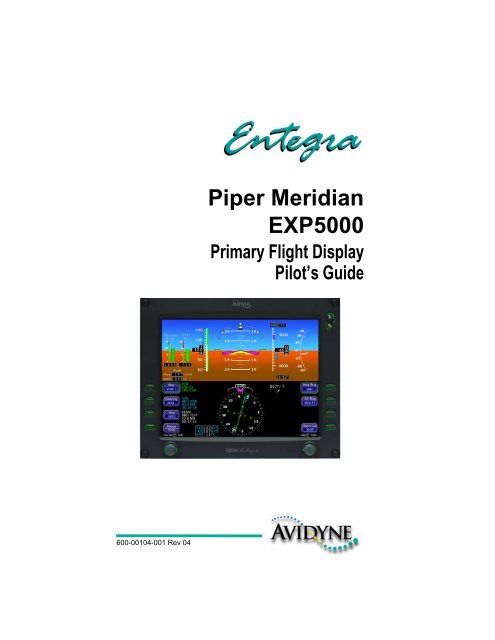
600-00104-001 Rev 04<strong>Piper</strong> <strong>Meridian</strong><strong>EXP5000</strong>Primary Flight DisplayPilot’s Guide
This page intentionally blank.
Document Revision HistoryDate Revision DescriptionSept. 30, 2005 00 Released per ECO-05-162Oct. 14, 2005 01 Updated per ECO-05-179Oct. 12, 2006 02 Updated per ECO-230Aug. 8, 2007 03 Updated per ECO-07-254Oct. 01, 2007 04 Updated per ECO-07-344This document is applicable to Software Part Number 530-00194-000.All materials are copyrighted including images that represent this softwareCopyright 2007 <strong>Avidyne</strong> Corporation. All rights reserved.600-00104-001 Rev 04 -i- Entegra <strong>EXP5000</strong> PFD
Table of Contents1 Introduction.............................................................. 1Notes and Warnings .................................................................... 1Copyrights and Trademarks ........................................................ 2AVIDYNE EXCLUSIVE LIMITED WARRANTY/LIMITATIONS ONLIABILITY .................................................................................... 32 <strong>EXP5000</strong> System Overview..................................... 5<strong>EXP5000</strong> Overview ..................................................................... 5<strong>EXP5000</strong> Upper Half Display ...................................................... 7Upper Half Display ................................................................ 7<strong>EXP5000</strong> Display Options................................................... 10<strong>EXP5000</strong> Lower Half Display .................................................... 12<strong>EXP5000</strong> Buttons and Knobs .................................................... 15Left Buttons and Knob......................................................... 15Nav, Bearing and Aux Data Blocks..................................... 17Right Buttons and Knob ......................................................193 Flying with the <strong>EXP5000</strong>........................................ 22Introduction................................................................................ 22Starting the <strong>EXP5000</strong> ................................................................ 23<strong>EXP5000</strong> Alignment Messages........................................... 24AHRS Alignment Errors ...................................................... 25Mag Cal Error...................................................................... 25Startup Settings ......................................................................... 26Setting Up the HSI..................................................................... 27Using GPS/VHF Systems with the <strong>EXP5000</strong> .............................29Flying With the Autopilot ............................................................ 30S-TEC 55X Autopilot Modes ............................................... 30Horizontal Modes ................................................................ 30Precision Flying with <strong>EXP5000</strong>...................................................32Obtaining Level Flight ......................................................... 32Flying a Constant Rate Turn ................................................32Using Trend Indicators........................................................ 33Using the <strong>EXP5000</strong> for Approaches.......................................... 34Precision Approaches ..........................................................34Flying a WAAS Approach.....................................................35Flying an Autopilot-Coupled WAAS Approach.....................36Flying an Autopilot-Coupled Approach (S-TEC 55X Only)...36600-00104-001 Rev 04 - ii - Entegra <strong>EXP5000</strong> PFD
Non-Precision Approaches ................................................. 37Missed Approach ................................................................ 374 Invalid Sensors and Error Conditions ................. 39Invalid Air Data .......................................................................... 40Invalid Heading.......................................................................... 41Crosscheck Monitor...................................................................42Warmstart Conditions ................................................................43Recoverable Attitude ................................................................. 44Invalid Attitude & Heading .........................................................45Invalid Engine Data ...................................................................46Nav Source Crosscheck ............................................................47Loss of Communication with Autopilot.......................................485 Using Dual PFDs ...................................................496 Software License....................................................56600-00104-001 Rev 04 -iii- Entegra <strong>EXP5000</strong> PFD
This page intentionally blank.Entegra <strong>EXP5000</strong> PFD -iv- 600-00104-001 Rev 04
1 IntroductionThis Pilot’s Guide provides information about the Entegra <strong>EXP5000</strong>PFD for the <strong>Piper</strong> <strong>Meridian</strong>.1.1 Notes and WarningsNotes and warnings provide guidance for the use of the <strong>EXP5000</strong>.<strong>Avidyne</strong> strongly suggests that you pay close attention to notes andwarnings for your own safety.For example:Note: Notes provide useful information about how to use the <strong>EXP5000</strong>Primary Flight Display.!Warnings are prefaced with exclamation points and denoteinformation that can prevent serious injury or death on thepart of the user.The instructions and warnings in this manual are not intended toreplace the instructions and warnings for other equipment on youraircraft. It is critical that you as the pilot in command have a completeunderstanding of the warnings, operating instructions, and limitationsfor all equipment installed on your aircraft.!!This manual assumes that the reader is an appropriatelylicensed pilot. <strong>Avidyne</strong> strongly recommends that you use the<strong>EXP5000</strong> only under VFR conditions until you are very familiarwith the <strong>EXP5000</strong>.If you have questions, please contact <strong>Avidyne</strong> at 800-284-3963 (800-AVIDYNE) or +1-781-402-7400 before operatingwith the Entegra PFD under IFR conditions.When using the <strong>EXP5000</strong>, be sure to cross-check the datadisplayed against other data sources for accuracy includingother flight deck instruments and charts.600-00104-001 Rev 04 -1- Entegra <strong>EXP5000</strong> PFD
Copyrights and Trademarks1.2 Copyrights and TrademarksAll trademarks and trade names are the property of their respectiveowners. All materials are copyrighted including images that representthis software.Copyright 2007 <strong>Avidyne</strong> Corporation. All rights reserved.Entegra <strong>EXP5000</strong> PFD -2- 600-00104-001 Rev 04
Introduction1.3 AVIDYNE EXCLUSIVE LIMITED WARRANTY/LIMITATIONS ON LIABILITY<strong>Avidyne</strong> warrants the Product manufactured by it against defects in material and workmanshipfor a period of twenty-four (24) months from delivery. If <strong>Avidyne</strong>'s Product fails to conform tothis warranty, <strong>Avidyne</strong>, in its sole discretion, will either repair or replace the Product or providea refund of the purchase price paid for the Product. This warranty is made upon the expressconditions that:(a) <strong>Avidyne</strong> is given prompt written notice of any claimed non-conformity in the Product, with areasonable explanation thereof;(b) The Product is returned to <strong>Avidyne</strong> or to an <strong>Avidyne</strong> authorized service facility;(c) The Product has not been altered in any manner other than as previously authorized by<strong>Avidyne</strong> in writing; and(d) Repairs to the Product have not been made by anyone other than <strong>Avidyne</strong> or an <strong>Avidyne</strong>authorized service facility.This warranty does not apply to any Product which is not installed, maintained and operated inaccordance with <strong>Avidyne</strong>'s written instructions or which is otherwise misused, including,without limitation, to any Product which is damaged due to improper installation, maintenanceor operation, tampering, alteration of serial numbers or other manufacturers data, lightning orother electrical source, or otherwise.If warranty protection is applicable to the Product, <strong>Avidyne</strong> will use reasonable efforts to repairor replace Product within ten (10) business days of its receipt of the Product.Any Product that has been repaired by <strong>Avidyne</strong> or replaced by <strong>Avidyne</strong> under this warranty willbe subject to remainder of the original warranty term applicable to the repaired or replacedProduct or will be warranted under the warranty terms above for ninety days from the date ofrepair or replacement, whichever period is longer.This exclusive limited warranty applies in lieu of and expressly supersedes and excludes allother representations, affirmations and/or warranties, whether express or implied, oral orwritten, including, without limitation, any warranty of merchantability, of fitness for a particularpurpose, of title and/or of non-infringement. purchaser expressly and knowingly agrees that noother representations, affirmations or warranties, whether express or implied, oral or written,form part of any purchase and sale transaction related to the product.<strong>Avidyne</strong>'s (and its affiliates') and any product component supplier's sole responsibility andliability related to the product or arising out of or related to its purchase, sale, performance,reliability or use are limited to its repair or replacement, or to a refund of the purchase price, inavidyne's sole discretion. in no event will avidyne (or its affiliates) or any suppliers of productcomponents be responsible or liable for any other damage of any nature whatsoever, includingdirect, indirect, incidental, consequential, special, loss of use, loss of revenue or profit,property damage, personal injury, wrongful death, or other damage (whether or not avidyne (orits affiliates) were notified of the possibility that any damage might be incurred), arising out ofor related to the product, its purchase or sale, its performance or reliability, or the use orinability to use the product, for any reason, including due to any product defect or defects orany action or inaction of any nature (including claimed or actual negligence or gross600-00104-001 Rev 04 -3- Entegra <strong>EXP5000</strong> PFD
AVIDYNE EXCLUSIVE LIMITED WARRANTY/LIMITATIONS ON LIABILITYnegligence) by <strong>Avidyne</strong> or any suppliers of product components. neither this exclusive limitedwarranty nor <strong>Avidyne</strong>'s or any product component supplier's responsibility or liability will in anyway be enlarged or otherwise altered due to avidyne's provision of technical support or trainingrelated to the product.Without limiting the foregoing, neither <strong>Avidyne</strong> (nor its affiliates) make any representations,affirmations or warranties regarding or related to products not manufactured by <strong>Avidyne</strong> orregarding or related to the performance or reliability of any such product, either alone or whenused with any product manufactured by <strong>Avidyne</strong>, or the suitability of any such product for usewith any product manufactured by <strong>Avidyne</strong>. <strong>Avidyne</strong> (and its affiliates) expressly disclaim anyand all representations, affirmations and/or warranties regarding or related to any suchproducts. in no event will <strong>Avidyne</strong> (or its affiliates) be responsible or liable for any damage ofany nature whatsoever, including direct, indirect, incidental, consequential, special, loss ofuse, loss of revenue or profit, property damage, personal injury, wrongful death, or otherdamage (whether or not <strong>Avidyne</strong> (or its affiliates) were notified of the possibility that anydamage might be incurred), arising out of or related to products not manufactured by <strong>Avidyne</strong>,the purchase or sale of such products, their performance or reliability, either alone or whenused with any product manufactured by <strong>Avidyne</strong>, or the suitability of any such product for usewith any product manufactured by <strong>Avidyne</strong>.This exclusive limited warranty also applies in lieu of and expressly supercedes and excludesall other rights any purchaser has or may have related to the product and/or arising out of orrelated to its purchase, sale, performance, reliability or use, either alone or with any otherproduct or products, whether in contract, in tort (including rights sounding in negligence, strictliability and misrepresentation), under statute, at law, in equity, or otherwise, and purchaserexpressly and knowingly waives all such rights to the fullest extent permitted by law. purchaseralso expressly and knowingly agrees that the product is not a consumer good.The foregoing four paragraphs define and limit <strong>Avidyne</strong>'s sole responsibility and liability andpurchaser's sole and exclusive remedies related to the product.Some jurisdictions may not allow the exclusion or limitation of warranties or liabilities, in whichcase, the above limitations or exclusions, or some of them, may not apply in thosejurisdictions.Entegra <strong>EXP5000</strong> PFD -4- 600-00104-001 Rev 04
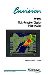
2 <strong>EXP5000</strong> System OverviewThis section contains the following information:● <strong>EXP5000</strong> Overview, page 5● <strong>EXP5000</strong> Upper Half Display, page 7● <strong>EXP5000</strong> Lower Half Display, page 12● <strong>EXP5000</strong> Buttons and Knobs, page 152.1 <strong>EXP5000</strong> OverviewThis section provides an overview of the Entegra <strong>EXP5000</strong>.123 34566Figure 1. The Entegra <strong>EXP5000</strong> PFD1) Brightness Control (BRT/DIM)—Allows you to adjust thedisplay brightness. Press the top button to brighten the display;press the bottom button to dim it. The default brightness is 75%.600-00104-001 Rev 04 -5- Entegra <strong>EXP5000</strong> PFD
<strong>EXP5000</strong> Overview2) Upper Half Display—The upper half of your <strong>EXP5000</strong> displaysinformation about your power plant, aircraft attitude, autopilotstatus (when equipped), navigation and more. This sectionincludes the following:■■■■■Engine instrumentsAttitude Direction Indicator (ADI)Airspeed Indicator (ASI)AltimeterVertical Speed Indicator (VSI)For information about the data displayed on the upper section ofthe <strong>EXP5000</strong>, see Section 2.2, "<strong>EXP5000</strong> Upper Half Display" onpage 7.3) Buttons—Buttons allow you to display new information orchange the display. Button labels change to reflect the currentenvironment.4) Lower Half Display—Displays the Horizontal Situation Indicator(HSI) and other details about direction, windspeed, and flightplans. The HSI can display a moving map to help you determineyour exact location. For more information, see Section2.3, "<strong>EXP5000</strong> Lower Half Display" on page 12.5) Air Data Data Block—Contains Air Data information.6) Left and Right Knobs—Knobs allow you to change the displayas indicated for the particular settings. The knob labels change toindicate the active function.■■Left button and knob functions are described in Left Buttonsand Knob, on page 15.Right button and knob functions are described in RightButtons and Knob, on page 19.Entegra <strong>EXP5000</strong> PFD -6- 600-00104-001 Rev 04
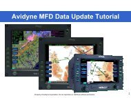
<strong>EXP5000</strong> System Overview2.2 <strong>EXP5000</strong> Upper Half Display215496871213151014311Figure 2. <strong>EXP5000</strong> Upper Half Display SymbolsUpper Half DisplayThe upper portion of the <strong>EXP5000</strong> contains the following information:1) Engine Start Parameters—During engine start or parameterexceedance, numeric displays of the following parameters areprovided.■Propeller Speed (Np)—Units of RPM.■ Gas Turbine Speed (Ng)—Units of %.■Oil Pressure (OP)—Units of PSI.2) Torque and Inter-Turbine Temperature (ITT) Gauges:■Torque Gauge—Displays current engine torque in footpounds.A numeric display below the torque analog indicatordisplays the torque value to the nearest 10 foot-pound. If thetorque enters the warning (red) area, the analog indicator barand numeric readout out display in red.600-00104-001 Rev 04 -7- Entegra <strong>EXP5000</strong> PFD
<strong>EXP5000</strong> Upper Half Display■ITT—Displays current engine ITT in °C. A numeric displaybelow the ITT analog indicator displays the ITT value to thenearest 5°C. If the ITT enters the caution (yellow) or warning(red) area, the analog indicator bar and numeric readout outdisplay in the corresponding color.3) Fuel Flow and Fuel Quantity:■■Flow—Displays the current engine fuel flow as a numericdisplay, to the nearest 1 pound per hour (or 1 kilogram perhour if metric units are selected).Total—Displays the total (left plus right) fuel quantity to thenearest 5 pounds (or 2 kilograms if you select metric units).4) Airspeed Tape—Indicated airspeed with a display range from 20kts to 300 kts.Each minor graduation represents 5 knots andeach 20 knot major graduation is labeled. Color bands on theairspeed tape are as follows:BandColorRedMeaningV NE V MO up to top of the airspeed tape.Green ■ V S up to V NO (For V NE aircraft).■ V S up to V MO .White V SO up to V FE .Red 20 kts up to V SO .This red band is removed during takeoff.5) Airspeed Window—Displays current indicated airspeed in knots.Hash marks are displayed below 20 knots.6) Skid/Slip Indicator—The black trapezoid is centered under theroll pointer in coordinated flight. Full scale deflection is the widthof the trapezoid.7) Bank Angle Indicator—The bank angle indicator is composed ofan inverted white triangle and an upright white triangular RollPointer. The upright white triangle points to the current bankangle. Graduations are at 0, 10, 20, 30, 45, and 60 degrees.(Note that the 0 and 45 degree marks are inverted triangles).8) Pitch Ladder—The pitch ladder is marked as follows:Entegra <strong>EXP5000</strong> PFD -8- 600-00104-001 Rev 04
<strong>EXP5000</strong> System Overview■ Every 2 1/2° within the range of ± 20°.■ Every 5° from +20° to +50° and -20° to -30°.■■■10° graduations of the pitch ladder have bar ends that pointtoward the horizon line.±90° is represented by small circles.Large chevrons, described in Section 3.7 Precision Flyingwith <strong>EXP5000</strong>, are only visible at excessive pitch angles andpoint toward the horizon (above +50° and below -30°).9) Aircraft Reference Symbol (ARS)—The ARS is fixed on thedisplay and provides a reference from which you can determineaircraft attitude. The <strong>EXP5000</strong> can be configured as one of twodifferent symbols:■■Yellow Delta—The DeltaARS displays in aircraftfor which Flight Directoris supported. The yellowoutriggers are used with the ARS symbol to provide areference for wings level flight.Flying W—The flying W displays inaircraft for which Flight Director isnot supported.10) Flight Director Steering Command Bars—Displays theaccuracy of the pilot or autopilot tracking the autopilotcommands. The pilot or autopilot is to steer the airplane towardthe command bars until the ARS is tucked into the steeringcommand bars.For more information about Flight Director, seeSection 3.6, "Flying with the Autopilot" on page 32.Note: The Flight Director steering command bars display only when FlightDirector is enabled and available and the aircraft is configured to display theDelta ARS symbol.11) Horizontal Deviation Indicator (HDI)—Displays when:■■The NAV source is VLOC.The localizer signal has been received.Or (if used with Garmin 400W/500W navigator)600-00104-001 Rev 04 -9- Entegra <strong>EXP5000</strong> PFD
<strong>EXP5000</strong> Upper Half Display■■The Nav source is GPSGPS horizontal deviation data has been receivedThe source of the HDI data is displayed immediately to the rightof the HDI (e.g., LOC, ILS or GPS). If the localizer signal is lost,the HDI is replaced with a red X and the source letters turn red. IfGPS data is lost, the HDI is removed from the display.To remove the HDI, change either the NAV source or the VOR/LOC frequency.12) Altitude Tape—Displays baro-corrected altitude with a displayrange from -1,000 feet to 35,000 feet. The box at the top of thetape displays the current value of the Alt Bug. Each minorgraduation represents 100 feet and each 500 foot graduation islabeled.13) Altitude Window—Displays the current baro-corrected altitude.14) Vertical Deviation Indicator (VDI)—Displays when:■ The Nav source is VLOC■ The ILS Glidescope signal has been received■ The VDI is not displayed for back course localizerapproachesOr (if used with Garmin 400W/500W navigator)■ The Nav source is GPS■ GPS vertical deviation data has been receivedTo remove the VDI display, change either the NAV Source or thelocalizer frequency.15) Vertical Speed Indicator (VSI)—Displays the vertical speed inFeet per Minute (fpm). The VSI shows ±3,000 fpm VSI scale.Scale graduations display every 200 fpm between ±2,000 fpm.When vertical speed is above scale limits, a digital readout of thecurrent vertical speed is displayed on the appropriate end of theVSI scale. The maximum displayed value of the digital readout is±4,000 fpm.<strong>EXP5000</strong> Display OptionsThe following display options are set during installation:Horizon Heading Reference MarksHorizon Heading Reference Marks provide heading information onthe ADI. If Horizon Heading Reference Marks are installed on yourEntegra <strong>EXP5000</strong> PFD -10- 600-00104-001 Rev 04
<strong>EXP5000</strong> System Overview<strong>EXP5000</strong>, the marks and labels appear at each quadrant (N, E, S, W)and mid-quadrant (NE, SE, SW, NW). The reference pointer for theHeading Marks is the apex of the ARS.Labeled VSpeedsUnder high power conditions, the V x and V Y labels are shown at thecorrect airspeeds for the Best Angle of Climb speed (V X ) and BestRate of Climb speed (V Y ).Under low power conditions, the V G label displays at the Best Glideairspeed as listed in the Airspeeds for Emergency Operations sectionof your aircraft Pilot Operating Handbook.Note: If your aircraft POH lists Best Glide airspeeds for multiple grossweights, V G is displayed as a range between the highest and lowest BestGlide airspeed. Make sure you consult the POH for the correct Best Glideairspeed for a particular gross weight.Barometer UnitsBarometer units can be displayed in In-Hg (Inches of mercury [default]), Mb(Millibars), or hPa (Hectopascals). The average sea-level pressure is29.92 in-hg or 1013.25 mb or hPa.Aircraft Reference SymbolDelta or Flying W. See the discussion of the Aircraft ReferenceSymbol in Section 2.2, "<strong>EXP5000</strong> Upper Half Display" on page 7 formore information.600-00104-001 Rev 04 -11- Entegra <strong>EXP5000</strong> PFD
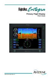
<strong>EXP5000</strong> Lower Half Display2.3 <strong>EXP5000</strong> Lower Half DisplayThe lower half of your <strong>EXP5000</strong> provides the Horizontal SituationIndicator (HSI) function and other information. You can choose todisplay the HSI as either a full 360° circle or as a 120° arc. The arcview is shown in Figure 4 on page 14.➥ All features can display in both the 360° and 120° views.674125839111013 12Figure 3. EHSI 360° View1) Magnetic Heading—A numeric indication of current aircraftmagnetic heading.2) Rate of Turn Indicator—The tip of the blue rate of turn indicatordisplays the current rate of turn. The indicator is marked for 1/2and full standard rate of turn. An arrowhead indicates a valuebeyond 1 1/2 standard rate. For more information, see Section"Using Trend Indicators" on page 33.3) Wind Vector—Displays the current wind speed and winddirection. The arrow indicates the direction of the wind relative tothe current aircraft heading.➥ After you turn, there will be a lag of several seconds inupdating current wind speed and direction.Entegra <strong>EXP5000</strong> PFD -12- 600-00104-001 Rev 04
<strong>EXP5000</strong> System OverviewThe wind vector on the HSI is very useful in any phase of flightwhere you need to take winds aloft into account. You can use acombination of the wind vector and projected track line innavigation tasks.Note: Under very light wind conditions or when wind speed cannot becalculated, wind data will be replaced by dashes.4) Projected Track Line—The dashed gray projected track lineoriginates from the aircraft present position symbol andterminates at the triangle along the outer edge of the compassrose. It displays a projection of the current ground track of theaircraft.➥ To take the guesswork out of determining proper crab anglesfor wind corrections, align the projected track line with thedesired course.Note: In dual-PFD equipped aircraft, differences between the two windvectors during light winds are normal.5) Bearing Pointer—The blue dual-line bearing pointer isassociated with the Bearing source and displays the currentbearing to the Bearing waypoint (GPS 1 or GPS 2) or to thestation (VLOC 1 or VLOC 2). A bearing pointer does not display ifyou tune the VLOC source to an ILS or LOC station.6) Course Deviation Indicator (CDI)—The green single-line CDIdisplays deviation from the set or desired course.7) To-From Flag—The small green arrow indicates whether you areheading to or from the current VOR or GPS waypoint. If you areheading to the VOR, the arrow points the direction you are flying.If from, the arrow points towards your most recent VOR orwaypoint.8) HSI Moving Map—Displays up to a maximum of 15 waypointsand labels from the active flight plan. The active leg of the flightplan is depicted in magenta, and all other legs of the flight planare depicted in white. The moving map will also display waypointsand labels of an approach and hold.9) HSI Map Range—When the moving map is selected for displayon the HSI via the View knob, the outer and inner rings of thecompass rose are labeled with range in nautical miles. Outer ringranges are 2, 5, 10, 20, 50, 100, and 200 NM.600-00104-001 Rev 04 -13- Entegra <strong>EXP5000</strong> PFD
<strong>EXP5000</strong> Lower Half Display10) Compass Rose—In both the 360° view and 120° arc view, theminor graduation marks represent 5 degrees, major graduationmarks represent 10 degrees, with every 30 degrees labeled. Theouter edge of the compass rose is marked with reference marks.11) Air Data Data Block—Displays:■■■True Airspeed (TAS) in knotsGround Speed (GS) in knotsOutside Air Temperature (OAT) in degrees Celsius12) MSG Annunciator—Illuminates when there is a message on theGPS navigator.13) WPT Annunciator—Illuminates when the GPS navigator detectsthe approaching of a waypoint.Figure 4. EHSI Arc (120°) ViewEntegra <strong>EXP5000</strong> PFD -14- 600-00104-001 Rev 04
<strong>EXP5000</strong> System Overview2.4 <strong>EXP5000</strong> Buttons and KnobsLeft Buttons and KnobThe left-hand buttons and knob on the Entegra <strong>EXP5000</strong> allow you toset the navigation configuration and course.The Nav (Primary Navigation) button is enabled by default (theenabled button has a green rim). To enable a different left-handbutton, press it. Once enabled, you can continue to press the buttonto change the setting.Note: The Nav button is re-enabled ten seconds after you last push orrotate the Bearing, Aux, and Range/View button. <strong>Avidyne</strong> suggests that youenable the desired button just before you change the knob.The state of each navigation button is displayed in the adjacent datablock, as shown in Figure 5. For information about the data blocks,see Nav, Bearing and Aux Data Blocks, on page 17.12345Figure 5. Left Knob & Buttons1) Nav (Primary Navigation)—Controls the source for the CourseDeviation Indicator (CDI) and adjacent data block. In a dual GPS/VHF navigator system, the available sources are: GPS 1, VLOC1, GPS 2, and VLOC 2.600-00104-001 Rev 04 -15- Entegra <strong>EXP5000</strong> PFD
<strong>EXP5000</strong> Buttons and Knobs2) Bearing (Secondary Navigation)—Controls the source for theBearing Pointer and adjacent data block. In a dual GPS/VHFnavigator system, the available sources are: GPS 1, VLOC 1,GPS 2, VLOC 2, ADF (if available), OFF.3) Aux (Auxiliary Navigation)—Controls the source of theadjacent data block only. In a dual GPS/VHF navigator system,the available sources are: GPS 1, VLOC 1, GPS 2, VLOC 2, ADF(if available), OFF.4) HSI Moving Map Range and View Button (Range/View)—When selected, Range/View allows the left knob to control theHSI’s moving map range and view:■■Pushing the knob—Cycles the HSI through the HSI views(360° with map; 360° without map, 120° with map; 120°without map).Rotating the knob—Changes the HSI moving map rangewhen the map is available.For more information about the HSI Map, see Section3.4, "Setting Up the HSI" on page 27.5) Left Knob—The function of the left knob changes depending onthe enabled button.■When Nav is enabled, the DTK (Direct Track) Set or Crs Setlabel displays when you can set a course, as shown in Table2.1. For information about setting a course, see Section3.5, "Using GPS/VHF Systems with the <strong>EXP5000</strong>" on page 29.Table 2.1 DTK or Crs Set LabelsNAV Source GPS Nav Condition Left Knob LabelGPS 1 or GPS GPS in Auto-Leg mode NoneGPS 1 or GPSGPS in OBS modeVLOC 1 or VLOC 2 Tuned NavAid is a VORVLOC 1 or VLOC 2 Tuned NavAid is an ILS orLOCEntegra <strong>EXP5000</strong> PFD -16- 600-00104-001 Rev 04
<strong>EXP5000</strong> System Overview■ When Range/View is enabled, the left knob controls the HSIview, and if applicable, the moving map range, as follows:Table 2.2 HSI Moving Map Range LabelsView SelectionWith moving mapWithout moving mapLeft Knob LabelNav, Bearing and Aux Data BlocksThe Nav data block content varies depending on the source, asfollows:Table 2.3 Primary Navigation SourceNAV SourceData Block FormatGPS 1 or GPS 2 ■ Waypoint Identifier■ Desired Track to Waypoint■ Distance to Waypoint■ Time-to-Go to WaypointVLOC 1 or VLOC 2 (VOR Tuned) ■ “VOR”■ VOR Frequency■ CourseVLOC 1 or VLOC 2 (ILS or LOC Tuned) ■ “ILS” or “LOC”■ Localizer Frequency■ Course600-00104-001 Rev 04 -17- Entegra <strong>EXP5000</strong> PFD
<strong>EXP5000</strong> Buttons and KnobsThe Bearing and Aux data block content depends on the source, asfollows:Table 2.4 Bearing or Aux SourceBearing or Aux SourceData Block FormatGPS 1 or GPS 2 ■ Waypoint Identifier■ Bearing to Waypoint■ Distance to Waypoint■ Time-to-Go to WaypointVLOC 1 or VLOC 2 (VOR Tuned) ■ “VOR”■ VOR Frequency■ Bearing to stationVLOC 1 or VLOC 2 (ILS or LOC Tuned) ■ “ILS” or “LOC”■ Localizer FrequencyADF (if available) ■ ADF Frequency (if available)■ ADF BearingOFF ■ BlankEntegra <strong>EXP5000</strong> PFD -18- 600-00104-001 Rev 04
<strong>EXP5000</strong> System OverviewRight Buttons and KnobAfter you press a button to enable it, use the right knob to change thetarget settings for that Bug (or setting). The knob label displays thecurrent functionality, as shown in Table 2.5 on page 21.Note: The Hdg Bug button is re-enabled ten seconds after you last push orrotate the knob to set the Alt Bug or Baro Set buttons. <strong>Avidyne</strong>recommends that you always select the desired button just before you usethe knob.23241245Figure 6. Right Buttons and Knob1) Heading Bug (Hdg Bug)—Controlled by the right knob whenHdg Bug is selected, the notched part of the magenta bug symbolindicates the current Heading Bug value. The Heading Bug ispositioned on the selected side of the compass rose and remainsin partial view when the HSI is in 120° view and the Heading Bug600-00104-001 Rev 04 -19- Entegra <strong>EXP5000</strong> PFD
<strong>EXP5000</strong> Buttons and Knobsvalue is outside the current compass rose field of view. The rangeis 001 to 360 degrees.• The Heading Bug is always filled, regardless of autopilot heading mode.• The Altitude Bug is always hollow, because it is not used as the autopilotaltitude preselect.Partial2)Altitude Bug (Alt Bug)—Controlled by the rightknob when you select Alt Bug. The notched part ofthe magenta bug symbol indicates the currentaltitude preselect value. When the selected valueis outside the current altimeter field of view, theBug is positioned at the appropriate end of thetape and remains in partial view (left). The Alt Bugdisplays on the altitude tape and the range ofvalues is the same as the altitude tape (–1,000feet to 35,000 feet).Press the Alt Bug button toswitch between the Alt Bugmodes (1,000 ft., 100 ft.,and 10 ft.). The defaultadjustment position is1,000 ft. Push the button toselect the mode, thenrotate the knob to adjustthe altitude for that mode.3) Altitude Preselect—Displays the numeric value of the AltitudeBug setting. When Alt Bug is selected, the numbers appear asblack on magenta.4) Barometric Correction Setting (Baro Set)—Controlled by theright knob when you select Baro Set, the value indicates thecurrent barometric correction setting. The baro correction maydisplay as inches of mercury (Hg), millibars (Mb), or hectopascals(Hp). Barometric units are set during <strong>EXP5000</strong> installation. Therange of allowable values is 27.50” to 31.50” (931 mb/HPa - 1067mb/HPa). The value appears in the button label and in theBarometric Correction Setting window.5) Right Knob—Once you enable one of the setting buttons, youcan either rotate or push the knob:Entegra <strong>EXP5000</strong> PFD -20- 600-00104-001 Rev 04
<strong>EXP5000</strong> System Overview■■Rotate—Allows you to change the desired setting onenumber at a time.Push:◆◆Hdg Bug and Alt Bug, and VSI Bug—Syncs the settingto the current heading, altitude, . After pushing the knob,you can then rotate it to easily make small adjustments toyour selected heading, altitude, and speed.Baro Set—Sets the barometric correction to theinternational standard setting of 29.92” (1013 hPa/mb).Table 2.5 summarizes the right knob settings:Table 2.5Right Knob SettingsActive Button Knob Label Rotary Action Push ActionHdg BugSets Heading Bug Syncs Heading Bugto current magneticheading.Alt Bug Sets Altitude Bug Syncs Altitude Bugto nearest 100’.Baro Set Sets Baro Sets Baro to 29.92.600-00104-001 Rev 04 -21- Entegra <strong>EXP5000</strong> PFD
3 Flying with the <strong>EXP5000</strong>3.1 IntroductionThis chapter contains all the basic information you need to use the<strong>EXP5000</strong>. Information includes:● Starting the <strong>EXP5000</strong>, page 23● <strong>EXP5000</strong> Alignment Messages, page 24● Setting Up the HSI, page 27● Using GPS/VHF Systems with the <strong>EXP5000</strong>, page 29● Flying with the Autopilot, page 30● Precision Flying with <strong>EXP5000</strong>, page 32● Using the <strong>EXP5000</strong> for Approaches, page 34600-00104-001 Rev 04 -22- Entegra <strong>EXP5000</strong> PFD
Flying with the <strong>EXP5000</strong>3.2 Starting the <strong>EXP5000</strong>The <strong>EXP5000</strong> includes a solid state Air Data and Attitude HeadingReference System (ADAHRS) which requires an alignment timebefore you are ready for flight.The <strong>EXP5000</strong> is designed to operate during engine start and shutdown procedures. <strong>EXP5000</strong> start-up is automatic once power isapplied via the battery switch.➥ A common startup procedure is to turn on BAT and conduct theaircraft preflight during the ADAHRS alignment process. ThePFD and the ADAHRS alignment process may restart whenyou start the engine.Approximately 10 seconds after turning on the <strong>EXP5000</strong>, the AHRSAlignment message box is displayed. In addition to AHRS Alignmentmessages, the box also displays the aircraft model, product name,and software part number. The informational messages automaticallytransition as described in Table 3.6 on page 24. When warm-up iscomplete, the message box is removed.Figure 7. Entegra <strong>EXP5000</strong> AHRS Alignment MessageTypical alignment time is 3 minutes but may take longer if the aircraftis subjected to motion. Air data (airspeed, altitude, vertical speed) willbecome valid prior to attitude data. Engine instruments are availableafter <strong>EXP5000</strong> start-up. The start-up message block displays a seriesof messages as shown in Table 3.6 on page 24, and is automaticallyremoved when warm-up is complete.600-00104-001 Rev 04 -23- Entegra <strong>EXP5000</strong> PFD
Starting the <strong>EXP5000</strong><strong>EXP5000</strong> Alignment MessagesNote: For faster alignments (3 minutes or less), <strong>Avidyne</strong> recommends thatyou do not move the aircraft until alignment is complete. The OK TO TAXImessage provides increased flexibility during ground operations, but it mayextend overall alignment time.Table 3.6Initialization PhasesAlignment Phase &Dialog DisplayedINITIAL AHRS ALIGNMENTREMAIN STATIONARYOK TO TAXI IN xx SECONDSAHRS WARMING UP 90 seconds, ifstationary.OK TO TAXIREADY FOR FINAL AHRSALIGNMENTBRING AIRCRAFT TO ASTOP AS SOON ASPRACTICALFINAL AHRS ALIGNMENTREMAIN STATIONARYREADY TO GO IN XSECONDSApproximate Pilot ActionDuration30 Seconds Remain StationaryUp to severalminutes ifmoving.5 seconds, ifstationary.Up to severalminutes ifmoving.You can taxi, but <strong>Avidyne</strong>recommends remainingstationary for faster overallalignmentsIf moving, bring aircraft toa stop as soon aspractical.40 - 45 seconds Remain stationaryEntegra <strong>EXP5000</strong> PFD -24- 600-00104-001 Rev 04
Flying with the <strong>EXP5000</strong>AHRS Alignment ErrorsWhile alignment and startup should proceed smoothly, in the case oferror, you may see one of the following messages in the AHRS Initbox:Table 3.7AHRS Alignment ErrorsMessageUNABLE TO COMPLETE ALIGNMENTMOTION SENSED - STOP AIRCRAFTAlignment Should Resume Within 2 Mins.UNABLE TO COMPLETE ALIGNMENTMAGNETIC ANOMALY IN THE AREARecommend Moving AircraftUNABLE TO COMPLETE ALIGNMENTSOFTWARE FAULT EXPERIENCEDRecommend Power CycleUNABLE TO COMPLETE ALIGNMENTATTITUDE SENSOR FAILURERecommend One-Time Power CycleUNABLE TO COMPLETE ALIGNMENTNO COMM. WITH MAGNETOMETERRecommended Pilot ActionStop aircraft as soon as practicaland wait for alignment to resume.Move Aircraft to different locationand begin startup operations.Power Cycle the PFD. Ifmessage displays again, contact<strong>Avidyne</strong> Technical Support.Power Cycle the PFD. Ifmessage displays again, contact<strong>Avidyne</strong> Technical Support.Contact an <strong>Avidyne</strong> EntegraCertified Service Center.Note: If any error message continues to display, contact an <strong>Avidyne</strong>Entegra Certified Service Center.Mag Cal ErrorIf the following alert is displayed, contact an <strong>Avidyne</strong> EntegraCertified Service Center as soon as practical.600-00104-001 Rev 04 -25- Entegra <strong>EXP5000</strong> PFD
Startup Settings3.3 Startup SettingsFigure 8. Default Startup SettingsWhen powered up, the Entegra <strong>EXP5000</strong> starts with the followingdefault values:● Hdg Bug, Alt Bug, Baro Set—The value from just beforeprevious shutdown● Map Range, Map View—The setting from just before previousshutdown● Alt Bug Mode—Thousands mode● Nav—GPS 1● Bearing—OFF● Aux—OFF● Right Side Active Button—Hdg Bug● Left Side Active Button—Nav● Right Knob—Sets Hdg Bug● Left Knob—InactiveEntegra <strong>EXP5000</strong> PFD -26- 600-00104-001 Rev 04
Flying with the <strong>EXP5000</strong>3.4 Setting Up the HSIThe Entegra <strong>EXP5000</strong> can integrate with single or dual GNS 400/500-series GPS or GPS/VHF navigator systems. When your<strong>EXP5000</strong> PFD is installed, it is configured for the number and type ofnavigator systems on board.Use the Nav button (Primary Nav) to select the navigator source forthe green single-line CDI and the moving map data. The active flightplan from the selected navigator unit drives the moving map on theHSI and will display up to 15 waypoints, including the curvedapproach path and holding pattern segments.Note: Garmin 400W/500W-Series GPS or GPS/VHF navigator systems arecapable of flying a parallel offset track. Since the 400W/500W navigators donot provide the PFD with information to depict the parallel offset flight plancorrectly, the PFD does the following when the 400W/500W is navigating toa parallel offset track:1) The offset flight plan is not depicted;2) The original non-offset flight plan is depicted on the HSI with thenon-offset active leg shown in white as opposed to magenta,which it is for non-offset flight plans.3) The To waypoint indentifier is removed from the Nav/Bearing/Aux datablock.Note: The Garmin 430W is capable of redrawing holding patterns based ongroundspeed. However, the 400W/500W navigators do not always transmitthe correct information to external devices to allow them to draw holdingpatterns correctly. In these situations, the depiction of the holding patternon the PFD will not match that of the 400/500W. If this occurs, correctguidance is still provided on the CDI/HDI and also to the autopilot while inGPSS mode.GPS 1 is also the primary source for ground-speed readout and arequired element for the wind vector calculation and display. If GPS 1is unavailable, ground speed and wind vector data are derived fromGPS 2. If the Nav source is selected to a VOR or localizer source, the600-00104-001 Rev 04 -27- Entegra <strong>EXP5000</strong> PFD
Setting Up the HSIHSI will display the appropriate course deviation indicator. Themoving map from the associated GPS will still be displayed.For more information about the Wind Vector and the HSI moving mapdisplay, see Figure 4, EHSI Arc (120°) View, on page 14.Use the Bearing button to select the Nav source for the blue doublelinebearing pointer. If the selected bearing source is a Localizer, thebearing pointer does not display.To take full advantage of the <strong>EXP5000</strong>, GPS 2 can be loaded withDirect-To waypoints, alternative flight plans, or Navaid frequencies toprovide additional guidance beyond what is loaded into GPS 1. Thisinformation can be selected for display on the <strong>EXP5000</strong> as theBearing or Aux.While using the crossfill capability of dual-configured GPS systems isfully supported and a common technique, it can prevent you fromtaking full advantage of the multiple Nav source display capability ofthe <strong>EXP5000</strong>.For information about loading data into your GPS/VHF unit see thePilot’s Guide for your GPS/VHF system.Note: The CDI on the <strong>EXP5000</strong>’s HSI comes from the selected Nav sourcewhich may be different from the CDI displayed on the GPS 1 or GPS 2displays.Entegra <strong>EXP5000</strong> PFD -28- 600-00104-001 Rev 04
Flying with the <strong>EXP5000</strong>3.5 Using GPS/VHF Systems with the <strong>EXP5000</strong>You can use the <strong>EXP5000</strong> to set a primary navigation course settingon the HSI when one of three conditions is met:● PFD Nav Source = GPS 1 or GPS 2 and the selected GPS/VHFsystem is in OBS mode.● PFD Nav Source = VLOC 1 or VLOC 2 and the currentfrequency is a VOR station.● PFD Nav Source = VLOC 1 or VLOC 2 and the currentfrequency is an ILS or localizer. In this case, you can set acourse for reference. The CDI is driven by the received localizersignal, regardless of the course set.The CDI scale on the <strong>EXP5000</strong>’s HSI is automatically set by theGPS/VHF system as a function of the Nav source you select with thePFD Nav button.Figure 9. Setting CDI Scale on <strong>EXP5000</strong>’s HSIThe source you select for Nav is coupled with the CDI button on theGPS/VHF unit, as follows:● When you toggle the Nav button on the <strong>EXP5000</strong> from GPS 1 toVLOC 1 and back, the CDI source on GPS 1 changes from GPSto VLOC and back to match the current Nav setting.● Similarly, when you toggle the CDI button on the GPS/VHF unitfrom GPS to VLOC and back, the Nav source on the <strong>EXP5000</strong>changes to match.➥ <strong>Avidyne</strong> recommends that you use the CDI button on GPS 1 totoggle the Nav source back and forth, especially for dual-GPSinstallations where the PFD Nav button cycles through all fourNav sources (GPS 1, VLOC 1, GPS 2, VLOC 2), and the CDIbutton on GPS 1 makes it easy to switch the <strong>EXP5000</strong>between GPS 1 and VLOC 1 and back.600-00104-001 Rev 04 -29- Entegra <strong>EXP5000</strong> PFD
Flying With the Autopilot3.6 Flying With the AutopilotYour Entegra <strong>EXP5000</strong>s are integrated with the S-TEC System 1500Autopilot.Flight Director steering command bars are displayed whencommanded to do so by the autopilot. Control of the S-TEC 1500vertical modes and display of mode information is available via theautopilot faceplate.The following is a description of the S-TEC 1500 autopilot modessupported by the Entegra PFD. The autopilot may only be coupled tothe GPS/NAV selected as the PFD Nav source. The autopilot maynot be coupled to the GPS/NAV selected as the PFD Bearing source.S-TEC 1500 Horizontal Modes1) Heading Capture/Hold Mode—Press the Hdg Bug button on thePFD and rotate the right knob to set a desired heading. Press theHDG button on the autopilot control head to engage headingmode. The autopilot will track the input heading. The autopilotcontrol head will indicate “HDG”. Select a new heading at anytime while the autopilot is in heading mode and the autopilot willtrack the new heading bug value.Note: See the S-TEC 1500 faceplate for engaged mode annunciation.2) Nav/Apr Mode—Press the NAV button on the autopilot controlhead to engage Nav mode.■■■■If GPS (Nav=GPS 1 or GPS 2) is the selected nav source onthe PFD, the autopilot will track the active flight plan usingGPS roll steering and will display “NAV GPSS”.If VLOC (Nav=VLOC 1 or VLOC 2) is the selected nav sourceon the PFD, the autopilot tracks the active VOR or localizersignal.When a localizer is the active Nav source, the autopilot willautomatically transition to APR mode when the localizer iscaptured and will display “NAV APR”.Glideslope capture is supported when the autopilot is in NAVAPR and altitude hold (“ALT”) modes.Entegra <strong>EXP5000</strong> PFD -30- 600-00104-001 Rev 04
Flying with the <strong>EXP5000</strong>Flight Director ModesThe Flight Director is a display of the flight profile commanded fromthe autopilot. Buttons on the S-TEC 1500 faceplate allow you toswitch the control of the autopilot modes between autopilot “AP”, andFlight Director “FD”. “FD” mode is a manual mode in which you areexpected to manually fly toward the command bars. When theautopilot is engaged in AP or FD mode, the Flight Director displays.The Flight Director command bars are limited to +/- 30° in roll and +/-15° in pitch with respect to the aircraft reference symbol.!S-TEC 1500 Autopilot Operation During PFD FailuresThe S-TEC 1500 requires a dual-PFD installation to operate.If either PFD fails, the autopilot cannot be engaged.600-00104-001 Rev 04 -31- Entegra <strong>EXP5000</strong> PFD
Precision Flying with <strong>EXP5000</strong>3.7 Precision Flying with <strong>EXP5000</strong>This section describes several techniques which take advantage ofthe <strong>EXP5000</strong>’s features to produce precision flight performance.Obtaining Level FlightYou can obtain level flight by placing the apex of the yellow deltashapedreference symbol a the pitch angle where the altitude trendvector is not displayed and the VSI reads zero (0). The pitch angle forlevel flight will vary with flight conditions, depending on speed,altitude and weight. There is no manual adjust capability (i.e. parallaxadjust).Flying a Constant Rate TurnThe proper technique for flying a constant rate turn involves using acombination of the turn indicator and the bank angle indicator. Figure10 shows a constant rate turn to the left.Figure 10. Flying a Constant Rate TurnInitiate the standard rate turn by banking to an initial bank angle of 20degrees with reference to the bank angle indicator, then adjust thebank angle to standard rate by reference to the standard rate turnindicator. Deviations from an intended bank angle are extremely easyto notice with the <strong>EXP5000</strong> ADI horizon line.Entegra <strong>EXP5000</strong> PFD -32- 600-00104-001 Rev 04
Flying with the <strong>EXP5000</strong>Using Trend IndicatorsUse the trend indicators to capture and maintain a desired airspeedand altitude by adjusting the pitch and/or power to the airspeed oraltitude you want. This results in a smooth capture of the desiredairspeed and altitude.Figure 11. Trend Indicators1) Airspeed Trend Indicator—The tip of the blue airspeed trendindicator displays the predicted airspeed six seconds into thefuture at the current rate of change. The Airspeed Trend Indicatordisplays changes greater than 1.8 knots/sec. An arrowheadindicates a value beyond the current tape field of view.2) Excessive Pitch Chevrons—Large white chevrons display atpitch values greater than +50 degrees and less than -30 degrees.In all cases, the chevrons point towards the horizon line.3) Rate of Turn Indicator—The tip of the blue rate of turn indicatordisplays the current rate of turn. The indicator is marked for 1/2and full standard rate of turn. An arrowhead indicates a valuebeyond 1 1/2 standard rate.4) Altitude Trend Indicator—The tip of the blue altitude trendindicator displays the predicted altitude six seconds into thefuture at the current rate of change. An arrowhead indicates avalue beyond the current tape field of view.600-00104-001 Rev 04 -33- Entegra <strong>EXP5000</strong> PFD
Using the <strong>EXP5000</strong> for Approaches3.8 Using the <strong>EXP5000</strong> for ApproachesPrecision ApproachesFigure 12. Flying an ILS ApproachFlying an ILS ApproachThe <strong>EXP5000</strong> is designed to take full advantage of the auto transitioncapability of the Navigator systems for flying a GPS flight plan endingin an ILS approach. In this case, the horizontal deviation indicator(HDI) and vertical deviation indicator (VDI) windows are displayed onthe ADI.The CDI course is automatically set to the inbound localizer courseresulting in a hands-free transition.As long as you select a localizer or ILS via the <strong>EXP5000</strong> Nav button,the HDI and VDI will automatically display when applicable localizerand glideslope signals are received. No pilot action is required.<strong>Avidyne</strong> recommends that you set the inbound course using the<strong>EXP5000</strong> Course Set knob to serve as reference during the localizerintercept and tracking. This is automatic if the Navigator system hasbeen set to Autoslew. The CDI deflection will be driven by thelocalizer signal itself, regardless of the course setting.Entegra <strong>EXP5000</strong> PFD -34- 600-00104-001 Rev 04
Flying with the <strong>EXP5000</strong>Flying a WAAS ApproachThe <strong>EXP5000</strong> is designed to take full advantage of the WAASapproach features provided in GNS-400W/500W series GPS or GPS/VHF navigators (Figure 13).Figure 13. Flying a WAAS ApproachWhen GPS is selected as the primary navigation source and theselected 400W/500W is providing guidance for a LPV, L/VNAV, andLNAV+V approach, the PFD provides horizontal and verticalguidance by means of the HDI and VDI.● For non-precision GPS approaches, the PFD will providehorizontal guidance by means of the HDI.● “GPS” will be annunciated next to the HDI to indicate that GPS isthe navigation source.● “TERM” or “APPR” will be annunciated next to the “GPS”annunciation to indicate when the navigator is in terminal orapproach mode, respectively.● A “GPS INTEG” annunciation is provided to the left of the HDI, ifthe 400W/500W has determined that satellite coverage isinsufficient for use of GPS as the primary navigation source. Ifthe GPS INTEG annunciation is displayed, VLOC should beselected as the navigation source.Refer to the 400W/500W pilot guide for more information.600-00104-001 Rev 04 -35- Entegra <strong>EXP5000</strong> PFD
Using the <strong>EXP5000</strong> for ApproachesFlying an Autopilot-Coupled WAAS ApproachTo perform an autopilot-coupled GPS WAAS approach, do thefollowing:●●●●Ensure that the nav source is set to GPS and that the selectednavigator has the approach loaded and activated.Autopilot should remain in GPSS mode until intercepting the finalapproach course (only GPSS mode will provide procedure turnand hold guidance).When the VDI is displayed, and the HDI annunciator is “GPSAPPR”, activate APR mode on the autopilot head. Provided thatALT mode is selected, and the airplane is within 50% scaledeflection on the HDI, GS mode and glide path capture capabilitywill be armed.As the glide path is approached, GS mode will become active tofollow the GPS generated glide path. This behavior is similar tothe glide slope function of an ILS approach.The autopilot will then track the horizontal and vertical guidanceprovided by the 400W/500W in the same way it would tracklocalizer and glideslope guidance. Refer to the autopilot’s user’sguide for Glideslope capture scenarios.Flying an Autopilot-Coupled ApproachTo perform an autopilot-coupled approach, ensure the approach hasbeen activated in the Navigator selected as the Nav source. Then:●●Press NAV on the autopilot control head to activate Nav mode.Press the APR button on the Autopilot control head to activatethe Glideslope capture capability.The autopilot will then track the Glidescope and localizer. Refer tothe autopilot user’s guide for Glideslope capture scenarios.<strong>Avidyne</strong> recommends that you set the Altitude Bug to the publishedapproach decision altitude to serve as a visual reference during theapproach.Note: For maximum situational awareness during all types of precision andnon-precision instrument approaches, always select and activate theapproach in the Navigator. This will enable the <strong>EXP5000</strong> to display theapproach waypoints on its moving map.Entegra <strong>EXP5000</strong> PFD -36- 600-00104-001 Rev 04
Flying with the <strong>EXP5000</strong>Note: Upon reaching the Final Approach Fix (FAF), ensure that the correctbaro setting is entered in both the <strong>EXP5000</strong> and standby altimeter. Alsoverify that the <strong>EXP5000</strong> and standby altimeter indicate the same altitude.Non-Precision ApproachesThe <strong>EXP5000</strong> is also designed to aid in the flying of non-precisionapproaches. Once the published approach has been activated in theNavigator system, the inbound course on the <strong>EXP5000</strong> will beautomatically set to match the inbound course of the publishedapproach.Flying an Autopilot-Coupled Non-Precision ApproachA recommended technique when performing an autopilot-couplednon-precision approach is:1) Select the HDG, NAV and ALT buttons on the autopilot while stilloutside the Final Approach Fix (FAF).2) Prior to reaching the FAF, if present, set the desired VS descentrate:■ Use the <strong>EXP5000</strong> HDG Bug to set the desired heading forclimbout/missed approach.■ Use the <strong>EXP5000</strong> Alt Bug to set the desired intermediatelevel off altitude or the minimum descent altitude (MDA) as avisual reminder.3) After crossing the FAF, select VS mode on the autopilot.4) Just prior to reaching MDA, select ALT on the autopilot tocommand altitude hold.Flying a Back Course Localizer ApproachThe <strong>EXP5000</strong> is designed to fully support flying back course localizerapproaches. To perform a back course localizer approach, ensure thefront course value is set via the <strong>EXP5000</strong> Course Set knob. As soonas the <strong>EXP5000</strong> determines that it is established on the back courselocalizer, the HDI source label indicates “LOC BCRS” and both theHDI and CDI display correct sensing. There is no further pilot action600-00104-001 Rev 04 -37- Entegra <strong>EXP5000</strong> PFD
Using the <strong>EXP5000</strong> for Approachesrequired. The VDI will not be displayed for back course localizerapproaches.Note: For coupled approaches, the Autopilot may have to be set to reversemode. Please consult the Autopilot POH for proper operation.Entegra <strong>EXP5000</strong> PFD -38- 600-00104-001 Rev 04
4 Invalid Sensors and Error ConditionsWhen the data coming into the <strong>EXP5000</strong> is unavailable or otherwiseinvalid, the <strong>EXP5000</strong> provides appropriate warnings and messages.This section discusses the following topics:● Invalid Air Data, page 40● Invalid Heading, page 41● Crosscheck Monitor, page 42● Warmstart Conditions, page 43● Recoverable Attitude, page 44● Invalid Attitude & Heading, page 45● Invalid Engine Data, page 46● Nav Source Crosscheck, page 47● Loss of Communication with Autopilot, on page 48600-00104-001 Rev 04 -39- Entegra <strong>EXP5000</strong> PFD
Invalid Sensors and Error Conditions4.1 Invalid Air DataFigure 14. Invalid Air DataIf air data becomes unavailable:1) Airspeed, altitude, and vertical speed data are removed andreplaced by red X’s.2) Wind Vector data is removed and replaced by dashes.3) True airspeed data is removed and replaced by dashes.If invalid air data occurs use the mechanical backup airspeedindicator and altimeter. <strong>Avidyne</strong> recommends that you crossreference the <strong>EXP5000</strong> attitude to the backup ADI when flyingwith invalid air dataNote: When the <strong>EXP5000</strong> determines that the air data is valid, it will resumeair data display.600-00104-001 Rev 04 -40- Entegra <strong>EXP5000</strong> PFD
Invalid Heading4.2 Invalid HeadingFigure 15. Invalid HeadingIf valid heading data becomes unavailable, heading data and HSInavigation data are removed from the display and replaced with a redX.Note: Refer to the aircraft compass for heading. Refer to the EX5000 MFDor GPS Navigator for ground track and flight plan.When heading data is determined to be valid, the display of headingand HSI navigation data will be restored.Entegra <strong>EXP5000</strong> PFD -41- 600-00104-001 Rev 04
Invalid Sensors and Error Conditions4.3 Crosscheck MonitorFigure 16. Crosscheck MonitorThe Entegra <strong>EXP5000</strong> comes equipped with a self-check monitor.When this monitor detects a condition that does not warrant removalof data, a CROSSCHECK ATTITUDE warning message displays.When this message is displayed, scan all backup instruments andauxiliary instruments (backup attitude indicator, backup airspeedindicator, and back up altimeter) to crosscheck the aircraft attitude.The warning message is automatically removed when the self-checkmonitor confirms the <strong>EXP5000</strong> attitude is valid.The message will not be displayed when air data is invalid (as shownon page 40). Cross referencing the <strong>EXP5000</strong> attitude to the backupADI is recommended during flight with invalid air data.Note: Highly dynamic maneuvering such as multiple linked lazy-8 leavesmay result in small pitch and/or bank errors. If the errors build up to anexcessive amount, the crosscheck attitude message may display.Note: In dual PFD installations, the CROSSCHECK ATTITUDE messageapplies to the selected ADAHRS source.600-00104-001 Rev 04 -42- Entegra <strong>EXP5000</strong> PFD
Warmstart Conditions4.4 Warmstart ConditionsThe <strong>EXP5000</strong> is capable of performing a warmstart from a fullyaligned condition when subjected to a power loss of less than 30seconds. In this event, the “PLEASE STANDBY” message in thewarmup box is displayed for approximately 2 seconds followed by the“ATTEMPTING QUICK RESTART” message and its countdown.There is no requirement to limit dynamic maneuvering during thiswarmstart attempt.Note: Two warmstart attempts in a row without a successful alignmentbetween attempts will result in a full alignment attempt.Figure 17. Quick Restart MessagesEntegra <strong>EXP5000</strong> PFD -43- 600-00104-001 Rev 04
Invalid Sensors and Error Conditions4.5 Recoverable AttitudeFigure 18. Recoverable Attitude SituationIf a recoverable attitude data failure occurs:1) All normal button labels are removed.2) Attitude data is removed from the display and replaced with a redX.3) A Fast Erect button label and message displays.When you press Fast Erect, the message will change to “Maintainstraight and level flight” until the 10 second count-down timerexpires. At that point, all attitude data is restored.!It is imperative that you obtain straight and level flight beforepressing Fast Erect. Use the backup instruments and/oroutside visual references to obtain straight and levelconditions.600-00104-001 Rev 04 -44- Entegra <strong>EXP5000</strong> PFD
Invalid Attitude & Heading4.6 Invalid Attitude & HeadingFigure 19. Invalid Attitude and HeadingIf valid attitude and heading data becomes unavailable, attitude data,wind vector data, heading data, and HSI navigation data are removedfrom the display.Note: You may be able to recover from a failed attitude condition by pullingboth PFD circuit breakers for less than 20 seconds. This will initiate awarmstart as described in Section 4.4, "Warmstart Conditions" on page 43.!If warmstart is unsuccessful, use back-up instruments forattitude and heading for the remainder of the flight. During IFRflights, proceed to the nearest VMC conditions and do not reenterIMC.Entegra <strong>EXP5000</strong> PFD -45- 600-00104-001 Rev 04
Invalid Sensors and Error Conditions4.7 Invalid Engine DataFigure 20. Invalid Engine DataIf valid engine data becomes unavailable:1) Torque and ITT tapes will be removed.2) Engine Instrument numeric readouts will be shown as whitedashes instead of digits.!It is likely that if data for one engine instrument is lost, thatdata will be lost for all engine instruments. Use engineinstruments on the Multi-Function Display (MFD) or CopilotPFD, if available. If engine sensors have failed and the data isnot available on the PFD or MFD, land as soon as practical.600-00104-001 Rev 04 -46- Entegra <strong>EXP5000</strong> PFD
Nav Source Crosscheck4.8 Nav Source CrosscheckWhen receiving valid navigation information from two radios tuned tothe same navigation aid, the <strong>EXP5000</strong> compares the data from thetwo and provides an alert if there is a miscompare.This comparison is only done when one of the radios is selected asthe primary navigation source.Figure 21. Localizer and Glideslope Crosscheck ErrorsFigure 22. VOR Crosscheck ErrorEntegra <strong>EXP5000</strong> PFD -47- 600-00104-001 Rev 04
Invalid Sensors and Error Conditions4.9 Loss of Communication with AutopilotIf autopilot data becomes unavailable, the autopilot annunciators areremoved from the display and a message with the text, “NOCOMMUNICATION WITH AUTOPILOT,” is displayed at the top of thePFD (Figure 23).Figure 23. Autopilot Data Unavailable MessageNote: It is normal to see this message when the PFD is turned on before theautopilot, but it should not persist for any longer than 20 seconds after theautopilot is turned on. If the message appears after the autopilot hasinitialized, cycle power to the PFD. If the problem persists, contact an<strong>Avidyne</strong> Entegra Certified Service Center as soon as practical.600-00104-001 Rev 04 -48- Entegra <strong>EXP5000</strong> PFD
5 Using Dual PFDsThis section discusses features specific to aircraft equipped with dualPFDs, as follows:● Selecting the ADAHRS Source, page 49● Synchronized and Non-synchronized Controls, page 51● Pilot Priority Switch, page 53● Dual PFD Error Conditions, page 545.1 Selecting the ADAHRS SourceFigure 23. Dual PFD DisplayFor dual PFD-equipped aircraft, each PFD has a complete andindependent ADAHRS. Each PFD can display ADAHRS data fromeither PFD. If one PFD is displaying the ADAHRS data from the otherPFD, a message displays at the center top of the PFD. As shown inthe example above, the message ADAHRS 2 displays on the PilotsPFD when it is displaying the Copilot PFD’s ADAHRS.600-00104-001 Rev 04 -49- Entegra <strong>EXP5000</strong> PFD
Using Dual PFDsSelect the ADAHRS source from a switch mounted on the aircraftinstrument panel. To locate the ADAHRS Source Selection switch,see the Pilot’s Operating Handbook for your aircraft.Note: When both PFDs are operating normally, <strong>Avidyne</strong> recommends thatyou set the ADAHRS source selection switch so that each PFD displays itsown ADAHRS data. This allows you to easily cross-check attitude,heading, and air data.In the case of an ADAHRS failure, set the switch to display the ADAHRS onthe remaining operating PFD.If the ADAHRS that is not selected fordisplay fails, is in alignment, or is in fasterect, a yellow message box describingthe condition displays in the lower rightcorner of the HSI.600-00104-001 Rev 04 -50- Entegra <strong>EXP5000</strong> PFD
Synchronized and Non-synchronized Controls5.2 Synchronized and Non-synchronized ControlsFigure 24. Dual PFDs – Synchronized ControlsWhen equipped with dual PFDs, some controls are synchronizedbetween the two PFDs to reduce confusion and improve situationalawareness. For these controls, adjusting any of the settings on onePFD also changes the other PFD.However, to provide maximum flexibility for the navigational needs oftwo crew members, other controls are not synchronized. Table 5.9lists the main PFD controls and whether or not they are synchronized:Table 5.9 Dual PFD Synchronized ControlsSynchronizedNot SynchronizedPrimary Nav Source selection Bearing Nav SourceCourse setting (if supported by Aux Nav Sourceselected Nav source and mode)Hdg BugHSI viewsAlt BugBaro SettingEntegra <strong>EXP5000</strong> PFD -51- 600-00104-001 Rev 04
Using Dual PFDsNote: While the bugs that control the autopilot can be set by either PFD, theautopilot uses only the Pilot PFD heading to measure its deviation. If theCopilot PFD heading differs from the Pilot PFD, the Copilot PFD may showa mismatch between the heading bug and the autopilot-controlled heading.600-00104-001 Rev 04 -52- Entegra <strong>EXP5000</strong> PFD
Pilot Priority Switch5.3 Pilot Priority SwitchOn dual-PFD equipped aircraft, the Pilot Priority switch mounted inthe flightdeck instrument panel allows you to inhibit the controls onthe Copilot PFD when a non-pilot is in the right-hand seat. See youraircraft Pilot’s Operating Handbook to locate the Pilot Priority switch.Figure 25. Uncoupled Copilot PFDThe Pilot Priority can be set as follows:● Uncoupled—The Nav, Hdg Bug, Alt Bug, and Baro Set buttonsare removed from the Copilot PFD, as shown in Figure 25. Thesesettings are controlled only from the Pilot PFD. The copilot cansee them on their PFD, but cannot make changes.Uncoupling the PFDs can be especially important when using theAutopilot in a mode where Bugs are controlling the aircraft.Uncoupling the copilot PFD prevents the passenger (a child, forexample) from accidentally changing the flight path.● Coupled—Button labels are restored, which reinstates copilotcontrol for the Nav, Hdg Bug, Alt Bug, and Baro Set parametersas described in Section 5.2, "Synchronized and NonsynchronizedControls" on page 51.Entegra <strong>EXP5000</strong> PFD -53- 600-00104-001 Rev 04
Using Dual PFDs5.4 Dual PFD Error ConditionsADAHRS MiscomparesIn dual-PFD equipped aircraft, the two PFDs compare their ADAHRSmeasurements for fault detection. If airdata, attitude, or headingmiscompare occurs, both PFD's will display the appropriate warningmessage adjacent to the affected instrument.Figure 26. ADAHRS Alert MessagesNotes: The ADAHRS miscompare messages are suppressed if:• One of the ADAHRS has failed, is in alignment, or is in fast erect.• The ADAHRS source selection switch is set to ADAHRS1 or ADAHRS2.• A PFD-to-PFD communication failure has occurred.PFD-to-PFD Communication FaultIf, at any point, one PFD loses contact with theother, a yellow error message will appear at thelower right corner of the HSI reading “No COMwith Pilot PFD” or “No COM with Copilot PFD.”600-00104-001 Rev 04 -54- Entegra <strong>EXP5000</strong> PFD
Dual PFD Error ConditionsIf you see the “No COM with Copilot PFD” error, a communicationfailure has occurred and the following dual PFD functions are nolonger available:●●●ADAHRS Source SelectionSynchronize ControlsADAHRS Comparison Monitoring.Vertical Modes with S-TEC 55X AutopilotThe vertical modes of the S-TEC 55X Autopilot (Alt Hold, Alt Capture,VS Mode, and so on) are wired to the pilot PFD only. If the copilotaltimeter or VSI differs from the pilot, the copilot PFD may display amismatch between the bugs and the autopilot controlled altitude orvertical speed.Entegra <strong>EXP5000</strong> PFD -55- 600-00104-001 Rev 04
6 Software License<strong>Avidyne</strong> Corporation (“<strong>Avidyne</strong>”) is willing to license this software, pilot'sguide, and related materials (the “Software”) only on the condition that youagree to all the terms of this agreement. Please read these terms carefully.Trademarks<strong>Avidyne</strong>, the <strong>Avidyne</strong> logo, Entegra, the Entegra Logo, FlightMax, and theFlightMax logo are trademarks of <strong>Avidyne</strong> Corporation. Other brands orproducts are the trademarks or registered trademarks of their respectiveholders and should be treated as such.License and Certain RestrictionsYou may use the Software on the FlightMax or Entegraon which it wasdelivered. You may not copy the Software for any purpose. You may nottransfer the Software or any rights under this Agreement to another partywithout this Agreement. The other party must agree to accept the terms ofthis Agreement. The Software contains trade secrets. You may notdecompile, reverse engineer, disassemble, or otherwise reduce the Softwareto human-readable form. You may not modify, adapt, translate, rent,sublicense, assign, lease, loan, resell for proof, distribute, or network theSoftware, disk or related materials or create derivative works based upon thesoftware or any part thereof. Title, ownership rights, and intellectual propertyrights in and to the Software belongs to <strong>Avidyne</strong> and its licensors. TheSoftware is protected by the copyright laws of the United States and byinternational copyright treaties. Title, ownership rights and intellectualproperty rights in and to the content accessed through the Software is theproperty of <strong>Avidyne</strong>, and where applicable, to the licensor content ownersand may be protected by applicable copyright or other law. This Agreementgives you no rights to such content.Government LicenseeIf you are acquiring the Software on behalf of any unit or agency of the UnitedStates Government, this provision applies. The Government acknowledges<strong>Avidyne</strong>'s representation that the Software and its documentation weredeveloped at private expense and no part of them is in the public domain.The Government acknowledges <strong>Avidyne</strong>'s representation that the Software is“Restricted Computer Software” as that term is defined in Clause 52.227-19of the Federal Acquisition Regulations (FAR) and is “Commercial ComputerSoftware” as that term is defined in Subpart 227.401 of the Department ofDefense Federal Acquisition Regulation Supplement (DFARS). TheGovernment agrees that: If the Software is supplied to the Department ofDefense (DoD), the Software is classified as “Commercial ComputerSoftware” and the Government is acquiring only “restricted rights” in theSoftware and its documentation as that term is defined in Clause 52.227-7013(c)(1) of the DFARS, and If the Software is supplied to any unit oragency of the United States Government other than DoD, the Government'srights in the Software and its documentation will be as defined in Clause52.227-19(c)(2) of the FAR.600-00104-001 Rev 04 -56- Entegra <strong>EXP5000</strong> PFD
Software LicenseRestricted Rights LegendUse, duplication, or disclosure by the Government is subject to restrictions asset forth in subparagraph (c)(1)(ii) of the Rights in Technical Data andComputer Software clause at DFARS 52.227-7013, and when applicablesubparagraphs (a) through (d) of the Commercial Computer-Restricted rightsclause at FAR 52.227-19, and in similar clauses in the NASA FARSupplement. - <strong>Avidyne</strong> Corporation, 55 Old Bedford Road, Lincoln, MA01773.Export Law AssurancesYou acknowledge and agree that the Software is subject to restrictions andcontrols imposed by the United States Export Administration Act and ArmsExport Control Act (the “Acts”) and the regulations thereunder. You agree andcertify that neither the Software nor any direct product thereof is being or willbe acquired, shipped, transferred or exported, directly or indirectly, into anycountry prohibited by the Acts and the regulations thereunder or will be usedfor any purpose prohibited by the same.MiscellaneousThis Agreement will be governed by the internal laws of the State ofMassachusetts. If any provision of this Agreement is held to beunenforceable, that provision will be removed and the remaining provisionswill remain in full force. This Agreement is the complete and exclusivestatement of the agreement between us which supersedes any othercommunications between us in relation to the subject matter of thisAgreement. This Software contains dated information. Use of the Software isbased on your understanding that this Software may not include all theinformation or the most current information relevant to your particularsituation. If you have any questions concerning this Agreement, you maycontact <strong>Avidyne</strong> by writing to <strong>Avidyne</strong> Corporation, 55 Old Bedford Road,Lincoln, MA 01773. You acknowledge that, in providing you with theSoftware, <strong>Avidyne</strong> and its licensors rely upon you to read this Agreement,understand it, and agree to be bound by its terms and not those contained inyour purchase order.If you do not agree to the terms of this license, <strong>Avidyne</strong> is unwilling to licensethe product to you. In such event, you may not use or copy the product, andyou should promptly contact <strong>Avidyne</strong> for instructions on return of the unusedproduct(s) for a refund.Copyright© 2007 <strong>Avidyne</strong> Corporation. All rights reserved. Reproduction of thispublication or any portion thereof by any means without the express writtenconsent of <strong>Avidyne</strong> Corporation is prohibited. For further information contact<strong>Avidyne</strong> Corporation, 55 Old Bedford Road, Lincoln, MA 01773, 781-402-7400. Information in this document is subject to change without notice.<strong>Avidyne</strong> reserves the right to change or improve their products and to makechanges in the content of this material without obligation to notify any personor organization of such changes or improvements.600-00104-001 Rev 04 -57- Entegra <strong>EXP5000</strong> PFD
AVIDYNE CORPORATION55 Old Bedford RoadLincoln, MA 01773Telephone: 781-402-7400Toll Free: 800-AVIDYNE (800-284-3963)FAX:781-402-7599www.avidyne.comP/N 600-00104-001 Rev 04 10/01©2007 <strong>Avidyne</strong> Corporation All Rights Reserved.<strong>Avidyne</strong> ® and FlightMax ® are registered trademarks of <strong>Avidyne</strong> Corp.