Model MT data sheet - MTS Sensors
Model MT data sheet - MTS Sensors
Model MT data sheet - MTS Sensors

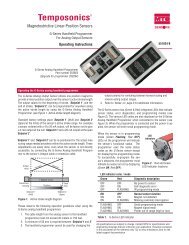
You also want an ePaper? Increase the reach of your titles
YUMPU automatically turns print PDFs into web optimized ePapers that Google loves.
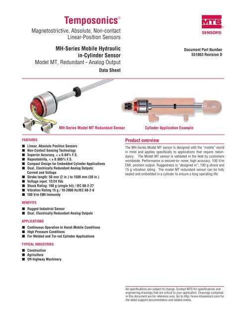
Temposonics ®Magnetostrictive, Absolute, Non-contactLinear-Position <strong>Sensors</strong>MH-Series Mobile Hydraulicin-Cylinder Sensor<strong>Model</strong> <strong>MT</strong>, Redundant - Analog OutputData SheetSENSORSDocument Part Number551063 Revision D®MH-Series <strong>Model</strong> <strong>MT</strong> Redundant SensorCylinder Application ExampleFEATURES• Linear, Absolute Position <strong>Sensors</strong>• Non-Contact Sensing Technology• Superior Accuracy, < ± 0.04% F.S.• Repeatability, < ± 0.005% F.S.• Compact Design for Embedded Cylinder Applications• Dual, Electrically Redundant Analog Outputs:Current and Voltage• Stroke length: 50 mm (2 in.) to 1500 mm (59 in.)• Voltage input: 12/24 Vdc• Shock Rating: 100 g (single hit) / IEC 68-2-27• Vibration Rating 15 g / 10-2000 Hz/IEC 68-2-6• 100 V/m EMI ImmunityProduct overviewThe MH-Series <strong>Model</strong> <strong>MT</strong> sensor is designed with the “mobile” worldin mind and applies specifically to applications that require redundancy.The <strong>Model</strong> <strong>MT</strong> sensor is validated in the field by customersworldwide. Performance is second-to- none; high accuracy, 100 V/mEMI, position output. Ruggedness is “designed in”; 100 g shock and15 g vibration rating. The model <strong>MT</strong> redundant sensor can be fullysealed and embedded in a cylinder to ensure a long operating life.BENEFITS• Rugged Industrial Sensor• Dual, Electrically Redundant Analog OutputsAPPLICATIONS• Continuous Operation In Harsh Mobile Conditions• High Pressure Conditions• For Welded and Tie-rod Cylinder ApplicationsTYPICAL INDUSTRIES• Construction• Agriculture• Off-highway MachineryAll specifications are subject to change. Contact <strong>MT</strong>S for specifications andengineering drawings that are critical to your application. Drawings containedin this document are for reference only. Go to http://www.mtssensors.com forthe latest support documentation and related media.
Product Specifications and Output OptionsProduct specificationsParametersOUTPUTMeasuredvariable:SpecificationsLinear Position measurementResolution: Range: Resolution:Outputs:Stroke length:Linearityuncorrected:Repeatability:Hysteresis:Outputs:Operatingvoltage:Powerconsumption:ELECTRONICSElectricalisolation:50 to 500 mm150 mm1,000 mm1.250 mm1,500 mmVoltage:0.25 to +1.75 Vdc0.5 to 4.5 VdcReverse:4.75 to 0.25 Vdc4.5 to 0.5 Vdc> 10kΩ at 12/24 Vdcpower supply0.1 mm0.18 mm0.24 mm0.3 mm0.38 mmCurrent:4 to 20 mAReverse:20 to 4 mA≤ 250Ω at 12/24 Vdcpower supply50 mm to 1500 mm (2 in. to 59 in.)Measured in 5 mm (0.20 in.) increments< ± 0.04% full stroke (minimum ± 0.100 mm0.003 in.)< ± 0.005% of full stroke± 0.1 mm (0.003 in.)Analog, dual electrically redundant:‡ Voltage: 0.25 to 4.75 Vdc , 0.5 to 4.5 Vdc(reverse: 4.75 to 0.25 Vdc, 4.5 to 0.5 Vdc)‡ Current: 4 to 20 mA(reverse: 20 to 4 mA)12/24 Vdc (8-32 Vdc)1 W maximum (per sensor)Polarityprotection: Up to -36 VdcOvervoltageprotection: Up to 36 Vdc500 Vdc (DC ground to machine ground)ParametersENVIRONMENTALOperatingconditions:EMC test:SpecificationsOperating: -40 °C (-40 °F) to +105 °C (221 °F)Storage: -30 °C (-22 °F) to +105 °C (221 °F)90% relative humidity, no condensation100 V/m:ISO 11452-5ISO 14982 to Agriculture and forest machineryShock rating: 100 g (single hit)/IEC standard 68-2-27(survivability)Vibrationrating: 15 g / 10 to 2000 Hz /IEC standard 68-2-6WIRINGConnectiontype:One 4-pin and one 5-pin with the M12 x1 connector and flange (provides IP69Kenvironmental protection when installed in acylinder).ROD STYLE SENSOR (MODEL <strong>MT</strong>)Material: Sensor rod: Stainless steel 1.4306 / AISI304LHousing: Stainless steel 1.4305 / AISI 303Mechanical assembly: Flange housing 48 mm(1.89 in.) dia., O-ring 40.87 x 3.53 mm NBR80, backup ring 42.6 x 48 x 1.4 PTFESealing: IP67 (IP69k when installed inside a cylinderwith M12 x 1 in. connection type)Pressurerating:Magnet type:Sensor rod, 10 mm (0.39 in.):Operating, 350 bar (5076 psi)Peak, 530 bar (7687 psi)Ring magnet,‡ Output range is factory programmable through entire strokeand is fully reversible.Output optionsThe MH-Series <strong>Model</strong> <strong>MT</strong> position analog sensor provides two, analog, electrically redundant outputs:• Voltage; 0.25 to 4.75 Vdc, 0.5 to 4.50 Vdc (reverse acting: 4.75 to 0.25 Vdc, 4.5 to 0.5 Vdc)• Current; 4 to 20 mA (reverse acting: 20 to 4 mA)MH-Series <strong>Model</strong> <strong>MT</strong>, Redundant Temposonics ® Linear-Position Sensor for Mobile Hydraulics, AnalogOutput Product Data Sheet, Document Part No.: 551063 Revision D, 12/11, 8/12, 12/12, 6/13 (US) 2<strong>MT</strong>S <strong>Sensors</strong>
Connections and wiring<strong>Model</strong> <strong>MT</strong> Rod-Style SensorConnections, Wiring and MountingCONNECTION TYPEThe Temposonics ® M12 connector system (shown in Figures 7, 8, 9 and 10 ), meets the most stringent protection requirements importantfor the difficult environmental conditions of mobile hydraulics applications. Protection type IP69K makes the robust metal housing not onlycompletely dust- and waterproof, even the harshest cleaning measures cannot damage the sensor.<strong>Model</strong> <strong>MT</strong>, rod-style redundant Sensor connector and pin assignments Drawings are for reference only, contact applications engineeringfor tolerance specific information.(1) Power Supply +12/24 Vdc4 3M12 x 110 mm(0.30 in.)12 mm(0.47 in.)24 mm (0.94 in.)17 mm(0.69 in.)Channel AA(2) N.C.(3) 0 Vdc(4) Output:mA, Vdc129 mm(0.35 in.)0 Vdc16H84.4 mm(0.17 in.) dia.Channel BB(1) Power Supply +12/24 Vdc(2) Output: mA, Vdc(3) 0 Vdc(4) N.C.(5) N.C.0 Vdc4 3512Figure 5. <strong>Model</strong> <strong>MT</strong> sensor connection dimensionsFigure 6. M12 x 1 Connector system pin assignmentsMOUNTING THE CONNECTOR SYSTEM TO THE CYLINDERFigure 7. The MH sensor is delivered by <strong>MT</strong>S together with the newconnector system: The connector insert carrier is alreadyconnected to the sensor electronics, i.e. no soldering, anycolor or connection mistake.Figure 9. Four standard screws must be tightened to mount theconnector flange on the cylinder.Figure 8. The connector insert is taken out of the cylinder througha bore hole. The flange housing can be snapped into positioneasily from outside.Figure 10 With a corresponding mating molded plug the connectorsystem fulfills an ingress protection (IP) of 69K.<strong>MT</strong>S <strong>Sensors</strong>5MH-Series <strong>Model</strong> <strong>MT</strong>, Redundant Temposonics ® Linear-Position Sensor for Mobile Hydraulics, AnalogOutput Product Data Sheet, Document Part No.: 551063 Revision D, 12/11, 8/12, 12/12, 6/13 (US)
Magnet selections and optional test kit<strong>Model</strong> <strong>MT</strong> Rod-Style SensorOrdering InformationMagnets and the MH-Series Analog/PWM tester must be ordered separetely. Refer to the table below for ordering information.Magnet selectionsPart no.Ring magnet, O.D. 17.4 mm 401032Ring magnet, O.D. 25.4 mm 400533Ring magnet, O.D. 33 mm 201542-2Magnet spacer 400633Optional accessoryMH-Series Analog/PWM testerThe MH-Series Tester includes:• MH-Series analog / PWM Tester• 12 Vdc battery charger with adapter• (adapter main plug EU, adapter main plug UK)• Cable with M12 x 1 connector• Cable with pigtailed wires• Carrying case• CD-Rom with user’s guidePart no.280618MH-Series Analog/PWM tester, part no.: 280618<strong>MT</strong>S <strong>Sensors</strong>7MH-Series <strong>Model</strong> <strong>MT</strong>, Redundant Temposonics ® Linear-Position Sensor for Mobile Hydraulics, AnalogOutput Product Data Sheet, Document Part No.: 551063 Revision D, 12/11, 8/12, 12/12, 6/13 (US)
Document Part Number: 551063, Revision D, 12/11, 8/12, 12/12, 6/13 (US)<strong>MT</strong>S and Temposonics are registered trademarks of <strong>MT</strong>S Systems Corporation.All other trademarks are the property of their respective owners.Printed in USA. Copyright © 2013 <strong>MT</strong>S Systems Corporation. All Rights Reserved in all media.SENSORS®<strong>MT</strong>S Systems Corporation<strong>Sensors</strong> Division3001 Sheldon DriveCary, North Carolina27513, USATel.: +1-800-633-7609Fax: +1-919-677-2343+1-800-498-4442e-mail: sensorsinfo@mts.comhttp://www.mtssensors.com<strong>MT</strong>S Sensor TechnologieGmbH & Co. KGAuf dem Schüffel 9D - 58513 Lüdenscheid, GermanyTel.: +49-2351-9587-0Fax: +49-2351-56491e-mail: info@mtssensor.dehttp://www.mtssensor.de<strong>MT</strong>S <strong>Sensors</strong> TechnologyCorporation737 Aihara-cho, Machida-shiTokyo 194-0211, JapanTel.: +81-42-775-3838Fax: +81-42-775-5516e-mail: info@mtssensor.co.jphttp://www.mtssensor.co.jp