NURBS in VRML
NURBS in VRML
NURBS in VRML

Create successful ePaper yourself
Turn your PDF publications into a flip-book with our unique Google optimized e-Paper software.
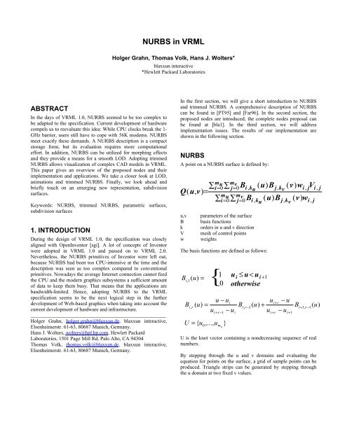
<strong>NURBS</strong> <strong>in</strong> <strong>VRML</strong>Holger Grahn, Thomas Volk, Hans J. Wolters*blaxxun <strong>in</strong>teractive*Hewlett Packard LaboratoriesABSTRACTIn the days of <strong>VRML</strong> 1.0, <strong>NURBS</strong> seemed to be too complex tobe adapted to the specification. Current development of hardwarecompels us to reevaluate this idea: While CPU clocks break the 1-GHz barrier, users still have to cope with 56K modems. <strong>NURBS</strong>meet exactly these demands. A <strong>NURBS</strong> description is a compactstorage form, but its evaluation requires more computationaleffort. In addition, <strong>NURBS</strong> can be utilized for morph<strong>in</strong>g effectsand they provide a means for a smooth LOD. Adopt<strong>in</strong>g trimmed<strong>NURBS</strong> allows visualization of complex CAD models <strong>in</strong> <strong>VRML</strong>.This paper gives an overview of the proposed nodes and theirimplementation and applications. We take a closer look at LOD,animations and trimmed <strong>NURBS</strong>. F<strong>in</strong>ally, we look ahead andbriefly touch on an emerg<strong>in</strong>g new representation, subdivisionsurfaces.Keywords: <strong>NURBS</strong>, trimmed <strong>NURBS</strong>, parametric surfaces,subdivision surfaces1. INTRODUCTIONDur<strong>in</strong>g the design of <strong>VRML</strong> 1.0, the specification was closelyaligned with OpenInventor [sgi]. A lot of concepts of Inventorwere adopted <strong>in</strong> <strong>VRML</strong> 1.0 and passed on to <strong>VRML</strong> 2.0.Nevertheless, the <strong>NURBS</strong> primitives of Inventor were left out,because <strong>NURBS</strong> had been too CPU-<strong>in</strong>tensive at the time and thedescription was seen as too complex compared to conventionalprimitives. Nowadays the average Internet connection cannot feedthe CPU and the modern graphics subsystems a sufficient amountof data to keep them busy. That means that the applications arebandwidth-limited. Hence, adopt<strong>in</strong>g <strong>NURBS</strong> to the <strong>VRML</strong>specification seems to be the next logical step <strong>in</strong> the furtherdevelopment of Web-based graphics when tak<strong>in</strong>g <strong>in</strong>to account thecurrent development of hardware and <strong>in</strong>frastructure._____________________________________________________Holger Grahn, holger.grahn@blaxxun.de, blaxxun <strong>in</strong>teractive,Elsenheimerstr. 61-63, 80687 Munich, Germany.Hans J. Wolters, wolters@hpl.hp.com, Hewlett PackardLaboratories, 1501 Page Mill Rd, Palo Alto, CA 94304Thomas Volk, thomas.volk@blaxxun.de, blaxxun <strong>in</strong>teractive,Elsenheimerstr. 61-63, 80687 Munich, Germany.In the first section, we will give a short <strong>in</strong>troduction to <strong>NURBS</strong>and trimmed <strong>NURBS</strong>. A comprehensive description of <strong>NURBS</strong>can be found <strong>in</strong> [PT95] and [Far96]. In the second section, theproposed nodes are <strong>in</strong>troduced; the complete nodes proposal canbe found at [bla1]. In the third section, we will addressimplementation issues. The results of our implementation areshown <strong>in</strong> the follow<strong>in</strong>g section.<strong>NURBS</strong>A po<strong>in</strong>t on a <strong>NURBS</strong> surface is def<strong>in</strong>ed by:∑Q(u,v)=u,vBkVwmu mvi= 0∑j = 0Bi, ( u)B ku j,( v)w kv i , j Vi, jmu m∑vi= 0∑j = 0 Bi, k u( u)Bj, k ( v)wv i , jparameters of the surfacebasis functionsorders <strong>in</strong> u and v directionmesh of control po<strong>in</strong>tsweightsThe basis functions are def<strong>in</strong>ed as follows:B i {( , 1u) =1 0ui≤ u
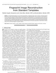
The normals are computed by tak<strong>in</strong>g the cross product of thesurface derivatives∂ ∂n = Q( u,v)× Q(u,v)∂u∂vand normaliz<strong>in</strong>g the result<strong>in</strong>g vector.This evaluation scheme is referred to <strong>in</strong> the literature as uniformtessellation. This method is staightforward to implement, lessCPU-<strong>in</strong>tensive and suitable for parallel comput<strong>in</strong>g. For a fixedtessellation it is possible to precompute all the necessary basisfunctions B i (u) and B j (v). In addition, some properties of <strong>NURBS</strong>can be exploited. The control po<strong>in</strong>ts are <strong>in</strong>variant totransformations. Thus the small number of control po<strong>in</strong>ts can betransformed <strong>in</strong>stead of the huge number of output vertices. Thevertices are lighted <strong>in</strong> screen space afterwards. Furthermore, theconvex hull property of <strong>NURBS</strong> states that the surface or curvelies completely with<strong>in</strong> the convex hull formed by its controlpolygon. Hence the control polygon can be used as bound<strong>in</strong>g boxfor cull<strong>in</strong>g. It is also known that by repeatedly perform<strong>in</strong>gsubdividision via knot <strong>in</strong>sertion [Far96] the control polygonconverges quadratically to the surface [Dahmen86]. By exploit<strong>in</strong>gthis fact, we can compute very tight bound<strong>in</strong>g hulls.As a drawback of a fixed step size the surfaces can beoversampled or undersampled: a flat surface may be broken up<strong>in</strong>to a very f<strong>in</strong>e mesh, or a surface of high curvature may berepresented by a coarse mesh. This problem is adressed <strong>in</strong> theadaptive subdivision scheme as described <strong>in</strong> [Pet94]. Adaptivetessellation approximates the surface more accurately, especially<strong>in</strong> cases of highly vary<strong>in</strong>g curvature, but is more CPU-<strong>in</strong>tensive.In our approach, we use a uniform tessellation due to its lessercomputational requirements. If the <strong>NURBS</strong> surface isparametrized appropriately, then the placement of the knot l<strong>in</strong>esreflects the surface properties well. In areas of dense knot l<strong>in</strong>es thesurface will be more complex than <strong>in</strong> areas with sparse knotl<strong>in</strong>es.Hence a tessellation formed by divid<strong>in</strong>g knot <strong>in</strong>tervals <strong>in</strong>to a fixednumber of sub<strong>in</strong>tervals will sample the surface accurately.for <strong>in</strong>tersection to f<strong>in</strong>d out if they are identical [KML95].Especially when render<strong>in</strong>g trimmed <strong>NURBS</strong>, the trimm<strong>in</strong>g curveshave to be checked. Patches may have different trimm<strong>in</strong>g curves<strong>in</strong> terms of control po<strong>in</strong>ts represent<strong>in</strong>g the curve.Trimmed <strong>NURBS</strong>To describe arbitrary shapes, we have to <strong>in</strong>troduce trimmed<strong>NURBS</strong> patches. Here, so-called trimm<strong>in</strong>g loops which arespecified <strong>in</strong> parameter space of a surface mark <strong>in</strong>valid regions ofthe <strong>NURBS</strong> patch doma<strong>in</strong>. Especially <strong>in</strong> the CAD doma<strong>in</strong>,trimmed <strong>NURBS</strong> are used to design objects with fluid shapes likeship hulls and aircraft or car bodies. Also <strong>in</strong> solid modell<strong>in</strong>gpatches conta<strong>in</strong><strong>in</strong>g holes are represented <strong>in</strong> trimmed form.Trimm<strong>in</strong>g loops consist of one or more trimm<strong>in</strong>g curves, whichare 2D <strong>NURBS</strong> curves or piecewise l<strong>in</strong>ear curves, ly<strong>in</strong>g <strong>in</strong>parameter space of the surface and form<strong>in</strong>g a closed loop.Degeneracies like self<strong>in</strong>tersect<strong>in</strong>g trimm<strong>in</strong>g loops and <strong>in</strong>tersect<strong>in</strong>gloops need special attention, <strong>in</strong> that they have to be split up <strong>in</strong>tonon <strong>in</strong>tersect<strong>in</strong>g loops.Two different approaches of tessellat<strong>in</strong>g trimmed surfaces can befound <strong>in</strong> literature: In [Luk93] and [LC93] the B-Spl<strong>in</strong>erepresentation is used for render<strong>in</strong>g. The render<strong>in</strong>g algorithm<strong>in</strong>volves the computation of <strong>in</strong>tersections of trimm<strong>in</strong>g curves withthe iso-l<strong>in</strong>es and triangulation. S<strong>in</strong>ce these operations are simplerand faster to perform on Bezier-representations than on B-Spl<strong>in</strong>es,algorithms presented <strong>in</strong> [RHD89], [KML96] and [AES94] firstconvert <strong>NURBS</strong> surfaces to Bezier surfaces. The algorithm <strong>in</strong>[RHD89] partitions each trimm<strong>in</strong>g curve <strong>in</strong>to monotonic segmentsfollowed by a special triangulation at the patch boundaries. Weshare this approach <strong>in</strong> our implementation which is stable andstraightforward to implement. The monotonic subdivision and thetriangulation may become a bottleneck [RHD89]. More recentresults as [KML96] present more efficient algorithms for thetriangulation, the computation of tight bounds and the exploitationof frame coherence.Boundary computationThere is considerable literature on step size computation foruniform tessellation such as [RHD89], [FMM86], [AES91],[KML96]. There are two categories of algorithms, the sizecriterion and the deviation criterion. The size criterion determ<strong>in</strong>esthe bound based on the size of the result<strong>in</strong>g triangles <strong>in</strong> screenspace. Apply<strong>in</strong>g this step size to uniform tessellation still meansthat smooth areas are oversampled because the step size is relatedto the maximum curvature. The deviation criterion computes abound on the maximum deviation of the tessellated surface fromthe <strong>NURBS</strong> surface. The deviation criterion produces good resultsbut is computationally expensive.CracksS<strong>in</strong>ce adjacent surfaces need not necessarily be tessellated withthe same step size, cracks will appear at the patch boundaries. Ifthe boundary curve of two surfaces has an identical parametricrepresentation, a strip of cov<strong>in</strong>g triangles can be generated at theboundary as described <strong>in</strong> [FMM86, RHD89]. If the control po<strong>in</strong>tsof the boundary do not match, boundary curves have to be testedFigure 1: Trimmed <strong>NURBS</strong> patch rendered with the glutessellator.
2. PROPOSED NODESNurbsSurfaceNurbsSurface {field SFInt32 uDimension 0 # [0, ∞)field SFInt32 vDimension 0 # [0, ∞)field MFFloat uKnot [] # (-∞,∞)field MFFloat vKnot [] # (-∞,∞)field SFInt32 uOrder 3 # [2, ∞)field SFInt32 vOrder 3 # [2, ∞)exposedField MFVec3f controlPo<strong>in</strong>t [] # (-∞,∞)exposedField MFFloat weight [] # (0, ∞)exposedField SFInt32 uTessellation 0 # (-∞,∞)exposedField SFInt32 vTessellation 0 # (-∞,∞)exposedField SFNode texCoord []field SFBool ccw TRUEfield SFBool solid TRUE}uDimension and vDimension def<strong>in</strong>e the number of control po<strong>in</strong>ts<strong>in</strong> the u and v dimensions.uOrder and vOrder def<strong>in</strong>e the order of surface. From amathematical po<strong>in</strong>t of view, the surface is def<strong>in</strong>ed by polynomialsof the degree order-1. The order of the curves uOrder and vOrdermust be greater than or equal to 2. An implementation may limituOrder and vOrder to a certa<strong>in</strong> number. The most common ordersare 3 (quadratic polynomial) and 4 (cubic polynomial), which aresufficient to achieve the desired curvature <strong>in</strong> most cases.The number of control po<strong>in</strong>ts must be at least equal to the order ofthe curve. The order def<strong>in</strong>es the number of adjacent control po<strong>in</strong>tsthat <strong>in</strong>fluence a given control po<strong>in</strong>t.controlPo<strong>in</strong>t def<strong>in</strong>es a set of control po<strong>in</strong>ts of dimensionuDimension * vDimension. This set of po<strong>in</strong>ts def<strong>in</strong>es a meshsimilar to the grid of an ElevationGrid, whereas the po<strong>in</strong>ts do nothave a uniform spac<strong>in</strong>g. Depend<strong>in</strong>g on the weight values and theorder, this hull is approximated by the result<strong>in</strong>g surface. Thenumber of uDimension po<strong>in</strong>ts def<strong>in</strong>e a polyl<strong>in</strong>e <strong>in</strong> u-directionfollowed by further u-polyl<strong>in</strong>es with the v-parameter <strong>in</strong> ascend<strong>in</strong>gorder. The number of control po<strong>in</strong>ts must be equal to or greaterthan the order. A closed B-Spl<strong>in</strong>e surface can be specified byrepeat<strong>in</strong>g the limit<strong>in</strong>g control po<strong>in</strong>ts and by specify<strong>in</strong>g a periodicknot vectorThe control vertex correspond<strong>in</strong>g to the control po<strong>in</strong>t P[i, j] on thecontrol grid is:P[i,j].x = controlPo<strong>in</strong>ts[i + ( j × uDimension)].xP[i,j].y = controlPo<strong>in</strong>ts[i + ( j × uDimension)].yP[i,j].z = controlPo<strong>in</strong>ts[i + ( j × uDimension)].zP[i,j].w = weight[ i + (j × uDimension)]where 0
necessary to resolve the set of the surface control po<strong>in</strong>ts as a 2dimensional area.NurbsGroupNurbsGroup {eventIn MFNode addChildreneventIn MFNode removeChildrenexposedField MFNode children []field SFVec3f bboxCenter 0 0 0 # (-∞,∞)field SFVec3f bboxSize -1 -1 -1 # (0,∞)or -1,-1,-1exposedField SFFloat tessellationScale 1.0}The NurbsGroup node groups a set of NurbsSurface nodes to acommon group. This provides a h<strong>in</strong>t to the browser to treat the setof NurbsSurface as a unit dur<strong>in</strong>g tessellation to enforcetessellation cont<strong>in</strong>uity along borders. The tessellationScaleparameter scales the tessellation values <strong>in</strong> lower-levelNurbsSurface nodes. If a set of NurbsSurfaces uses a match<strong>in</strong>g setof controlPo<strong>in</strong>ts along the borders, this results <strong>in</strong> a commontessellation stepp<strong>in</strong>g.NurbsPositionInterpolatorNurbsPositionInterpolator {}eventIn SFFloat set_fractionexposedField SFBool fractionAbsolute TRUEexposedField SFInt32 dimension 0exposedField MFFloat knot []exposedField SFInt32 order 4exposedField MFVec3f keyValue []exposedField MFFloat keyWeight []eventOut SFVec3f value_changedNurbsPositionInterpolator describes a 3D <strong>NURBS</strong> Curve us<strong>in</strong>gdimension keyValue, keyWeight, knot and order. Send<strong>in</strong>g aset_fraction <strong>in</strong>put computes a 3D position on the curve, which issent by value_changed. The set_fraction value is used as the <strong>in</strong>putvalue for the tessellation function. Thereby the knot coresponds tothe key field of a conventional <strong>in</strong>terpolator node, i.e. if theset_fraction value is with<strong>in</strong> [0;1] and the knot vector with<strong>in</strong> [0;2]only the half of the curve is computed. To traverse an arbitraryknot span with the normal <strong>in</strong>put span of [0;1] of a TimeSensornode a mapp<strong>in</strong>g function can be activated by sett<strong>in</strong>g thefractionAbsolute to FALSE.It is under consideration to expand the functionality to alsocompute tangents:exposedField SFBool computeTangent FALSEeventOut SFVec3f tangent_changedThe tangent is computed if the computeTangent field is TRUE.This eventOut can be used to compute a frame of reference at thecurrent position along the curve.Us<strong>in</strong>g a <strong>VRML</strong> PositionInterpolator, it is not possible to specify asmooth movement like a path along a circle until the curve issampled to a very f<strong>in</strong>e resolution. In a lot of exist<strong>in</strong>g <strong>VRML</strong>content, the data for Interpolators make up a substantial portion ofthe total size of the <strong>VRML</strong> file. Us<strong>in</strong>g Spl<strong>in</strong>e- (<strong>NURBS</strong>-) based<strong>in</strong>terpolation, we hope that this amount of data can be reduced.Feedback from content developers and tool vendors is required toevaluate this node and its usability and data reduction capabilities.NurbsTextureSurfaceNurbsTextureSurface {field SFInt32 uDimension 0 # [0, ∞)field SFInt32 vDimension 0 # [0, ∞)field MFFloat uKnot [] # (-∞,∞)field MFFloat vKnot [] # (-∞,∞)field SFInt32 uOrder 3 # [2, ∞)field SFInt32 vOrder 3 # [2, ∞)exposedField MFVec2f controlPo<strong>in</strong>t [] # (-∞,∞)exposedField MFFloat weight [] # (0, ∞)}The NurbsTextureSurface node is a <strong>NURBS</strong> surface exist<strong>in</strong>g <strong>in</strong>the parametric doma<strong>in</strong> of its surface host specify<strong>in</strong>g the mapp<strong>in</strong>gof the texture onto the surface. The tessellation process generates2D texture coord<strong>in</strong>ates, which means additional computationaleffort <strong>in</strong> a frame-by-frame tessellation. If theNurbsTextureSurface is undef<strong>in</strong>ed, texture coord<strong>in</strong>ates arecomputed by the client on the basis of parametric step sizewithout any performance penalty. Conventional vertex parametersdo not apply on <strong>NURBS</strong> because triangles are only available afterpolygonization, but the conventional texture transform may beused.TrimmedSurfaceTrimmedSurface {eventIn MFNode addTrimm<strong>in</strong>gContoureventIn MFNode removeTrimm<strong>in</strong>gContourexposedField MFNode trimm<strong>in</strong>gContour []exposedField SFNode surfaceNULL}The TrimmedSurface node def<strong>in</strong>es a <strong>NURBS</strong> surface that istrimmed by a set of trimm<strong>in</strong>g loops. The surface field conta<strong>in</strong>sthe NurbsSurface that shall be trimmed. The trimm<strong>in</strong>gContourfield, if specified, shall conta<strong>in</strong> a set of Contour2D nodes. Thecontours specify the area to trim out follow<strong>in</strong>g the trimm<strong>in</strong>g rulealigned to the Open Inventor def<strong>in</strong>ition [Wer94]. A area <strong>in</strong>side aloop is discarded if the loop is def<strong>in</strong>ed <strong>in</strong> a clockwise direction. Ifthe loop is def<strong>in</strong>ed <strong>in</strong> a counterclockwise direction the area <strong>in</strong>sideis reta<strong>in</strong>ed and outside is discarded. The outermost contour mustbe def<strong>in</strong>ed <strong>in</strong> a counterclockwise direction. The contours may notbe self-<strong>in</strong>tersect<strong>in</strong>g or <strong>in</strong>tersect other contours.Contour2DContour2D {eventIn MFNode addChildreneventIn MFNode removeChildrenexposedField MFNode children []field SFVec3f bboxCenter 0 0 0 # (-∞,∞)field SFVec3f bboxSize -1 -1 -1 # (0, ∞)or -1,-1,-1}The Contour2D node groups a set of curve segments to acomposite contour. The children have to form a closed loop withthe first po<strong>in</strong>t of the first child repeated as the last po<strong>in</strong>t of the lastchild and the last po<strong>in</strong>t of a segmet repeated as the first po<strong>in</strong>t ofthe consecutive one. The segments must be of the type
NurbsCurve2D or Polyl<strong>in</strong>e2D and must be enumerated <strong>in</strong> thechild field <strong>in</strong> consecutive order accord<strong>in</strong>g to the topology of thecontour.NurbsCurve2DNurbsCurve2D {field MFFloat knot []field SFInt32 order 3exposedField MFVec2f controlPo<strong>in</strong>t []exposedField MFFloat weight []exposedField SFInt32 tessellation 0}suitable tessellation bound simply based on the desiredsmoothness. In addition, this value can be used to weight thepolygon budget of objects. Essential objects are given a hightessellation value to ensure a smooth surface; less importantobjects get a lower tessellation value because some coarseness istolerable.The NurbsCurve2D node def<strong>in</strong>es a trimm<strong>in</strong>g segment that is partof a trimm<strong>in</strong>g contour <strong>in</strong> the u-v doma<strong>in</strong> of the surface. If theNurbsCurve2D forms a closed contour, it may be used as aContour2D node.Polyl<strong>in</strong>e2DPolyl<strong>in</strong>e2D {exposedField MFVec2f po<strong>in</strong>t []}The Polyl<strong>in</strong>e2D node def<strong>in</strong>es a l<strong>in</strong>ear curve segment as a part of atrimm<strong>in</strong>g contour <strong>in</strong> the u-v doma<strong>in</strong> of a surface.3. IMPLEMENTATIONOur implementation <strong>in</strong> the <strong>VRML</strong> browser blaxxun Contact [bla2,web] proves the usage of <strong>NURBS</strong> <strong>in</strong> the <strong>VRML</strong> doma<strong>in</strong>. Allproposed nodes except the NurbsTextureSurface have beensuccessfully implemented. In favour of fast and stable process<strong>in</strong>ga uniform tessellation was applied as recommended <strong>in</strong> [KML96].Various render<strong>in</strong>g pipel<strong>in</strong>es fullfill the requirements of differentplatforms (Figure 2). As a reference implementation we used theOpenGL tessellator located <strong>in</strong> the glu-library. The <strong>NURBS</strong>surface parameters are directly handed over to the correspond<strong>in</strong>gOpenGL functions. This method is easy to implement, butperformance is low.To use the built <strong>in</strong> render<strong>in</strong>g pipl<strong>in</strong>e <strong>in</strong> our client, we polygonize<strong>NURBS</strong> models and store the result<strong>in</strong>g mesh data. If no dynamictessellation is required, the performance penalty is avoidedalltogether. For low-end CPUs or complex models, this methodcan be used to tessellate <strong>NURBS</strong> surfaces <strong>in</strong> a preprocess<strong>in</strong>g step.In case of dynamic tessellation (view-depended render<strong>in</strong>g) the<strong>in</strong>troduction of thresholds for the tessellation values m<strong>in</strong>imizes thecomputational load. If the tessellation value is altered by morethan 10% the vertex cache is flushed and a new tessellation cycleis <strong>in</strong>voked.Current chip architectures like the Intel ISSE or the AMD3DNow! allow to parallelize the computations <strong>in</strong>volved <strong>in</strong> thepolygonization. An ISSE optimized tessellation with additionallyoptimized light<strong>in</strong>g and transformation showed best results. Thispipel<strong>in</strong>e exploits the fact that CVs are <strong>in</strong>variant undertransformations. Transform is sped up by apply<strong>in</strong>g the costlymatrix multiplication to the small amount of CVs. After thetessellation process the transformed vertices are lit.In the current implementation stage no step size computation isperformed. As a first step we encourage the content author to set aFigure 2: pipel<strong>in</strong>es for tessellation and render<strong>in</strong>gView dependent render<strong>in</strong>gThe implementation is targeted to dynamic tessellation whichallows view-dependend render<strong>in</strong>g. Like the classical LOD,<strong>NURBS</strong> objects can be scaled down accord<strong>in</strong>g to the viewer’sdistance from the object. We have <strong>in</strong>troduced a quality factordescrib<strong>in</strong>g the render<strong>in</strong>g quality by means of triangles per screensize of the object. This value is comparable with the screen basedtolerance shown <strong>in</strong> section 1, because both values specify theresolution of an object. In contrast to the screen based tolerancethe computation is very simple but is not directly related to thecurvature of the objecttriangles(scale)Quality =bbox(dist)Withtriangles ( scale)= ( uTess + 1) * scale*(vTess + 1) * scale* 2Quality:triangles(scale):bbox(dist):Describes render<strong>in</strong>g quality of an objectNumber of triangles of an objectDiameter of the bound<strong>in</strong>g box <strong>in</strong> screen spaceThe quality factor is specified by the tessellation values <strong>in</strong> <strong>VRML</strong>.If the quality is assumed to be constant the scale value alters withthe distance of the viewer to the object. An additional feedbackloop can scale the quality factor accord<strong>in</strong>g to the CPU speedreflect<strong>in</strong>g <strong>in</strong> the frame rate. The algorithm keeps the framerateconstant by scal<strong>in</strong>g the <strong>NURBS</strong> content at any given CPU speed.Of course, this implies that the whole scene has to be designed forscal<strong>in</strong>g: There has to be reasonable space for upscal<strong>in</strong>g anddownscal<strong>in</strong>g the tessellation and thus the appearance of an objectif mov<strong>in</strong>g away from the target platform. However, scalability isnot unlimited: In the average scene <strong>NURBS</strong> content is scaleddown very fast with CPU frequency s<strong>in</strong>ce certa<strong>in</strong> portions of theoverall computational effort do not decrease. The drawbacks ofCPU based scal<strong>in</strong>g are that the authors lose control over theappearance of the object s<strong>in</strong>ce the client itself cont<strong>in</strong>uously altersthe object’s resolution. Proper lower bounds have to be def<strong>in</strong>ed to
avoid <strong>in</strong>tolerable undersampl<strong>in</strong>g of the model. To overcome theseshortcom<strong>in</strong>gs additional parameters could be <strong>in</strong>troduced: Authorscould specify the tessellation strategy or the lower boundary of thequality.Other parametric shapes like cyl<strong>in</strong>ders, cones and spheres canprofit from the <strong>NURBS</strong> LOD as well. A client could composethese shapes with <strong>NURBS</strong> “beh<strong>in</strong>d the scenes,“ allow<strong>in</strong>g seamlessscal<strong>in</strong>g of the objects.Large-scale <strong>NURBS</strong> surfaces are not addressed <strong>in</strong> this approachand have to be subdivided by hand. In the worst case, a hugesurface is very coarse nearby while totally oversampled <strong>in</strong> itsremote parts. To avoid boundary cracks of adjacent surfaces dueto the view dependent render<strong>in</strong>g <strong>NURBS</strong> objects have to begrouped <strong>in</strong> a NurbsGroup node.Trimmed <strong>NURBS</strong>The usage of the <strong>NURBS</strong> tessellator of OpenGL for the presentednodes <strong>in</strong> the context of trimmed <strong>NURBS</strong> is straightforward. TheContour2D node signals OpenGL the beg<strong>in</strong>n<strong>in</strong>g and the end of atrimm<strong>in</strong>g loop. The NurbsCurve2D coresponds to agluNurbsCurve and the Polyl<strong>in</strong>e2D is the <strong>VRML</strong> counterpart ofgluPwlCurve. The performance of glu's <strong>NURBS</strong> implementationon the average PC (table 1) is low. In the trimmed <strong>NURBS</strong> caseperformance decreased considerably <strong>in</strong> comparison to theuntrimmed one, reserv<strong>in</strong>g the OpenGL implementation to highend workstations, at least until graphic boards support<strong>in</strong>g <strong>NURBS</strong><strong>in</strong> hardware on basis of the OpenGL API arise on the market.Therefore <strong>in</strong> our implementation the performance penalty oftessellation was avoided by cach<strong>in</strong>g the tessellated model. Torender even complex CAD models an optimal polygon count isachieved by employ<strong>in</strong>g adaptive tessellation. Techniques rely<strong>in</strong>gon realtime tessellation such as the animation of control verticesand view depended render<strong>in</strong>g are out of the scope <strong>in</strong> thisimplementation, but various LOD modells could be generated <strong>in</strong> apreprocess<strong>in</strong>g step. Further work has to be done <strong>in</strong> us<strong>in</strong>g trimmed<strong>NURBS</strong> for LODs.4. ResultsFor test<strong>in</strong>g we take as a common scenario a scene with multiple<strong>NURBS</strong> objects shown at high resolution and exploit<strong>in</strong>g theadvantage of arbitrary resolution for a LOD. Multiuser worldswith a huge number of avatars mov<strong>in</strong>g around or a shopp<strong>in</strong>g mallconta<strong>in</strong><strong>in</strong>g a large number of products show this behaviour.A sample implementation [bla2] of file exporters for 3d StudioMax 2.5 and 3.0 respectively supports the new nodes. The<strong>NURBS</strong> export function is fully <strong>in</strong>tegrated <strong>in</strong> the conventional<strong>VRML</strong>97 file exporter <strong>in</strong> the 3.0 version. In another approach weconvert Open Inventor files to <strong>VRML</strong>. This method isstraightforward s<strong>in</strong>ce the specification of the proposed nodes isclosely related to the one of Open Inventor <strong>NURBS</strong>. Support<strong>in</strong>gauthor<strong>in</strong>g tools like 3d Studio Max seems to be more complex:Internal <strong>NURBS</strong> data structures like ruled, loft and blendedsurfaces have to be reduced to the basic <strong>NURBS</strong> surface. Varioustools especially <strong>in</strong> the CAD doma<strong>in</strong> support the Open Inventor fileformat. For professional modell<strong>in</strong>g Alias Wavefront can be used.IFS <strong>in</strong> D3D OpenGL Preprocess<strong>in</strong>g ISSE60fps 5fps 38fps 45fpsTable 1: Comparison between tessellation pipel<strong>in</strong>es. The sceneconta<strong>in</strong>ed an animated <strong>NURBS</strong> patch. Uniform tessellationwas configured to 5000 triangles. The frame rate <strong>in</strong>creasesnoticeable if the patch is stored as a IndexedFaceSet.Animation with <strong>NURBS</strong>The frame-by-frame tessellation allows us to alter the position ofthe control po<strong>in</strong>ts on the fly. To achieve effects like mov<strong>in</strong>gwaves with conventional meshes, many po<strong>in</strong>ts have to beanimated at the cost of huge data size of Coord<strong>in</strong>ateInterpolatorsor complex scripts. By transferr<strong>in</strong>g this problem to <strong>NURBS</strong>, onlys<strong>in</strong>gle control po<strong>in</strong>ts have to be animated. Data size is kept verysmall and scripts are very simple.Currently this technique is only limited by the lack of suitableauthor<strong>in</strong>g tools. Awesome effects can be achieved by-hand edit<strong>in</strong>gthe <strong>VRML</strong> file, but as the complexity of objects <strong>in</strong>creases, toolshave to be used. A sample implementation based on 3D StudioMAX shows the power of <strong>NURBS</strong> animations. The sampledanimation path is approximated by a spl<strong>in</strong>e and exported as aNurbsPositionInterpolator.CompressionThe figures presented <strong>in</strong> this section can only give a idea of thecompression factor, s<strong>in</strong>ce the factor largly depends on the degreeof curvature of the model. A <strong>NURBS</strong> model <strong>in</strong> 3d Studio Maxwas exported to the <strong>VRML</strong>97 <strong>NURBS</strong> format and to aconventional IndexedFaceSet with a resolution such that themodel did not show any render<strong>in</strong>g artefacts. However, thiscomparison assumes that the <strong>NURBS</strong> model is shown at itsoptimal resolution.Figure 3 Triangulation of a trimmed <strong>NURBS</strong> patch byadaptive tessellation
Figure 4 The Knight <strong>NURBS</strong> avatar composed of several<strong>NURBS</strong> patches. Even at close ups the avatar stays smooth.The avatar is taken out of the Knight <strong>NURBS</strong> demo ofLunatic Interactive (www.lunatic.de).IFS<strong>NURBS</strong>a) curved surface 66K (6.8K Polygons) 7Kb) Knight <strong>NURBS</strong> 2MB (40K Polygons) 200KTable 2 File size <strong>in</strong> KByte. a) A tool generated sphererepresent<strong>in</strong>g an average curved surface was exported as<strong>NURBS</strong> surface (without expoit<strong>in</strong>g the special characteristicsof a sphere) and as a mesh. b) A <strong>NURBS</strong> avatar shown <strong>in</strong> fig.4.Speed improvement with LODDepend<strong>in</strong>g on the scene, the LOD can speed up the render<strong>in</strong>gprocess tremendously. Especially <strong>in</strong> a multiuser sceneario wheremany avatars are mov<strong>in</strong>g <strong>in</strong> a scene, the LOD has a tremendousimpact on the performance. In a typical multiuser scenario, thecomplexity of the environment is negligible <strong>in</strong> comparison to thatof 50 or even 100 avatars. Typically, avatars are tool-generatedand thus only poorly <strong>VRML</strong>-optimized. Experiments with<strong>NURBS</strong> avatars have shown acceleration of at least 2x. Author<strong>in</strong>gvarious LOD models for the conventional LOD node of <strong>VRML</strong> isa time-consum<strong>in</strong>g process whereas with <strong>NURBS</strong> the LODs comefor free.IFS<strong>NURBS</strong>fps 8 24polygons 150K 35KTable 3 Frame rate <strong>in</strong>creases by factor 3 <strong>in</strong> this example whenemploy<strong>in</strong>g <strong>NURBS</strong> avatars with LOD <strong>in</strong>stead ofIndexedFaceSet based avatars. The overall polygon load of thescene decreased from 150K polygons to 35K s<strong>in</strong>ce only theavatars close to the camera are of high resolution.Figure 5 A scene with 10 high resolution avatars (15KPolygons) positioned <strong>in</strong> different distances to the viewer wasrendered as IndexedFaceSet and as <strong>NURBS</strong> model with LOD.The avatar was provided by the courtesy of okupi(www.okupi.com).5.SUBDIVISION SURFACESRecently, subdivision surfaces have ga<strong>in</strong>ed more attention as apossible alternatives to <strong>NURBS</strong>. In particular, <strong>in</strong> areas such asanimation and enterta<strong>in</strong>ment, subdivision surfaces have beenemployed. The reason for their <strong>in</strong>creas<strong>in</strong>g popularity is the factthat it is possible to generate geometry with arbitrary topologywithout <strong>in</strong>troduc<strong>in</strong>g trimm<strong>in</strong>g. This simplifies the user <strong>in</strong>teractionconsiderably and also elim<strong>in</strong>ates the robustness problems whichare <strong>in</strong>herent to trimmed <strong>NURBS</strong>.The basic idea of subdivision surfaces is the follow<strong>in</strong>g: Given is apolygonal mesh M 0 . A ref<strong>in</strong>ed mesh M 1 is created by subdivid<strong>in</strong>geach face <strong>in</strong>to a collection of subfaces. Typically, the vertices ofthe new mesh M 1 are computed as weighted averages of thevertices of the old mesh. Repeated application of this subdivisionstep leads to a smooth limit surface. The most popular schemesare Catmull-Clark subdivision [CC78] and Loop subdivision[Loo87]. The two schemes differ <strong>in</strong> that Catmull-Clark is basedon rectangles and the limit surface is a bicubic B-Spl<strong>in</strong>e. Loop‘sscheme is based on triangles. For commercial applications,Catmull-Clark is favored s<strong>in</strong>ce it directly generalizes the bicubictensor product B-Spl<strong>in</strong>es.This scheme has been used at Pixar for the creation of geometry <strong>in</strong>the short film Geri‘s game. In [DKT98] , the authors describetechniques developed by Pixar for modell<strong>in</strong>g sharp creases and fortexture mapp<strong>in</strong>g subdivision surfaces. Catmull-Clark subdivisionsurfaces are also implemented <strong>in</strong> Alias/Wavefront Maya.Evaluation of Subdivision SurfacesIt was a long-held belief that there is no direct way of evaluat<strong>in</strong>g asubdivision surface efficiently. Look<strong>in</strong>g at Figure 6 we can seethat almost everywhere the subdivision surface consists ofquadrilaterals which forms the control net of a bicubic B-Spl<strong>in</strong>e.Only around the extraord<strong>in</strong>ary vertices (vertices of valence notequal 4) does the surface not correspond to a B-Spl<strong>in</strong>e. Stam[Sta98] showed that even around extraord<strong>in</strong>ary vertices, it is
possible to evaluate the surface directly and efficiently. This canbe achieved by transform<strong>in</strong>g to a suitable basis, the eigenbasiswhich correpsonds to the power basis <strong>in</strong> regular regions. Hence, itis now much more practical to <strong>in</strong>corporate subdivision surfaces<strong>in</strong>to a model<strong>in</strong>g framework and to have them coexist withstandard <strong>NURBS</strong>.effective with current hardware and can save considerablebandwidth. Besides this obvious advantage of data compression,the LOD is a key feature. Def<strong>in</strong><strong>in</strong>g various levels of detail of amodel is not left up to the author but computed automatically bythe application.As a first step, work on the standardization of the proposed<strong>NURBS</strong> nodes needs to be done. Secondly, a standard for thetessellation and for the LOD technique have to be agreed upon toguarantee same visual appearance of objects <strong>in</strong> variousimplementations.Further work has to do be done <strong>in</strong> the field of author<strong>in</strong>g solutions.Due to the complexity of <strong>NURBS</strong>, objects cannot be modeled byhand <strong>in</strong> a text editor. We have to develop file exporters and fileconverters for the majority of the author<strong>in</strong>g tools to <strong>in</strong>crease theacceptance of <strong>NURBS</strong> <strong>in</strong> the community of content developers.Look<strong>in</strong>g farther ahead, one can imag<strong>in</strong>e to <strong>in</strong>corporate subdivisionsurfaces as well. Aga<strong>in</strong>, the issue of author<strong>in</strong>g solutions will haveto be addressed.Figure 6 Subdivision mesh with extraord<strong>in</strong>ary vertices. Onlythe marked patches can not be evaluated directly as bicubic B-Spl<strong>in</strong>es.Level of Detail ControlOne of the strengths of subdivision surfaces is the built-<strong>in</strong>multiresolution hierarchy. A mesh can be ref<strong>in</strong>ed by perform<strong>in</strong>gadditional subdivision steps. Conversely, it is also possible tocoarsen the mesh by apply<strong>in</strong>g mesh decimation techniques. In[ZSS97], the authors describe techniques for add<strong>in</strong>g detail locally,which allows to edit the model <strong>in</strong> a restricted region. It is alsoshown how one can traverse the multiresolution hierarchy <strong>in</strong>order to perform adaptive render<strong>in</strong>g. This enables the applicationto trade off frame rates for level of detail as described <strong>in</strong> Section3.SummaryIt is possible to put forth a proposal for subdivision surfaces <strong>in</strong> thefuture which can make use of the <strong>NURBS</strong> standard proposed <strong>in</strong>this paper. Subdivision surfaces address some issue which areproblematic for <strong>NURBS</strong> such as the model<strong>in</strong>g of arbitrarytopology. On the other hand, <strong>NURBS</strong> are well-established <strong>in</strong> theeng<strong>in</strong>eer<strong>in</strong>g community and they are superior for model<strong>in</strong>g <strong>in</strong> aneng<strong>in</strong>eer<strong>in</strong>g context. It is difficult to compare the storage andhence the transmission requirements. A model which has lots ofdetail <strong>in</strong> a local region favors a subdivision surface s<strong>in</strong>ce it allowsto add detail locally, whereas <strong>in</strong> <strong>NURBS</strong> we have to modify thepatch globally. On the other hand, stor<strong>in</strong>g a full multiresolutionhierarchy can <strong>in</strong>crease the transmission cost for subdivisionsurfaces, whereas LOD control comes essentially for free whenrender<strong>in</strong>g <strong>NURBS</strong>. In any case, both respresentations yieldsignificant compression ratios when compared to tessellatedmodels.6. CONCLUSION<strong>NURBS</strong> present a great opportunity to meet the requirements ofcurrent hardware and the Internet. With <strong>NURBS</strong> scalable webapplication can be created which react to the configuration of theclient system. Practical experience has proven that <strong>NURBS</strong> are
REFERENCES[AES91] S.S. Abi-Ezzi, L.A. Shirman. Tessellation of curvedsurfaces under highliy vay<strong>in</strong>g transformations. Proceed<strong>in</strong>gs ofEurographics 91, pages 385-397, 1991[AES94] S.S. Abi-Ezzi, S. Subramaniam, Fast DynamicTessellation of Trimmed <strong>NURBS</strong> Surfaces, Compter GraphicsForum, Vol. 13 (3), 1994[bla1]http://www.blaxxun.com/developer/contact/3d/nurbs/overview.html[Sta98] J. Stam, Exact Evaluation of Catmull-Clark SubdivisionSurfaces at Arbitrary Parameter Values. Computer GraphicsProceed<strong>in</strong>gs (SIGGRAPH 98) pp 395-404, 1998[web] source code of blaxxun Contact:http://www.web3d.org/TaskGroups/source/blax<strong>in</strong>dex.html[Wer94] J. Wernecke, The Inventor Mentor, Addison-Wesley,1994[ZSS97] D. Zor<strong>in</strong>, P. Schroeder, W. Sweldens, InteractiveMultiresolution Mesh Edit<strong>in</strong>g. Computer Graphics Proceed<strong>in</strong>gs(SIGGRAPH 97) pp. 259-268, 1997[bla2] blaxxun contact:http://www.blaxxun.de/download/contact/<strong>in</strong>dex.html[Dah86] W. Dahmen: Subdivision algorithms convergequadratically, J. Comp. Appl. Math., Vol 16., pp. 125-158, 1986[DKT98] T. DeRose, M. Kass, T. Truong, Subdivision Surfaces <strong>in</strong>Character Animation. Computer Graphics Proceed<strong>in</strong>gs(SIGGRAPH 98), pp 85-94, 1998[Far96] G. Far<strong>in</strong>, Curves and Surfaces for Compter AidedGeometric Design: A Practical Guide, 4 th Edition, AcademicPress, Boston 1996[FMM86] D. Filip, R. Magedson, R. Markot. Surface algorithmsus<strong>in</strong>g bounds on derivatives. CAGD (3), 295-311, 1986[KML96] S. Kumar, D. Manocha, A. Lastra, Interactive Displayof large scale <strong>NURBS</strong> models, IEEE Transactions onvisualization and Computer Graphics, Vol. 2, December, 1996[LC93] W.L. Luken and Fuhua Cheng, Render<strong>in</strong>g TrimmedNURB Surfaces, Computer Science Research Report18669(81711), IBM Research Division, 1993[Luk93] W.L. Luken, Tessellation of Trimmed NURB Surfaces,Computer Science Research Report 19322(84059), IBM ResearchDivision, 1993[Loo87] C. Loop, Smooth Subdivision Surfaces Based onTriangles. Master‘s thesis, University of Utah, Department ofMathematics, 1987[Pet94] J.W. Peterson, Tessellation of <strong>NURBS</strong> Surfaces, GraphicGems IV, Academic Press, p.286-320, Boston, 1994[PT95] L. Piegl, W. Tiller, The <strong>NURBS</strong> Book, Spr<strong>in</strong>ger,Heidelberg, 1995[RHD89] A. Rockwood, K. Heaton, T. Davis. Realtime render<strong>in</strong>gof trimmed surfaces. In Proceed<strong>in</strong>gs of ACM Siggraph, pages107-117, 1989[sgi]http://www.sgi.com/Technology/Inventor/<strong>VRML</strong>/<strong>VRML</strong>Design.html