Wilkins 950 XL 975 XL .75 inch thru 2 inch Double ... - Irrigation Direct
Wilkins 950 XL 975 XL .75 inch thru 2 inch Double ... - Irrigation Direct
Wilkins 950 XL 975 XL .75 inch thru 2 inch Double ... - Irrigation Direct

Create successful ePaper yourself
Turn your PDF publications into a flip-book with our unique Google optimized e-Paper software.
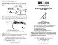
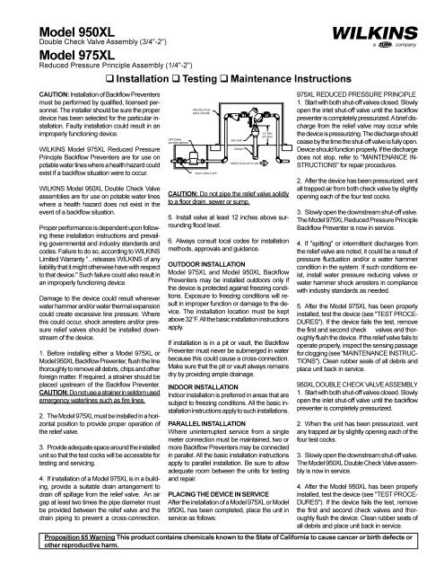
Model <strong>950</strong><strong>XL</strong><strong>Double</strong> Check Valve Assembly (3/4"-2")Model <strong>975</strong><strong>XL</strong>Reduced Pressure Principle Assembly (1/4"-2")q Installation q Testing q Maintenance InstructionsacompanyCAUTION: Installation of Backflow Preventersmust be performed by qualified, licensed personnel.The installer should be sure the properdevice has been selected for the particular installation.Faulty installation could result in animproperly functioning device.WILKINS Model <strong>975</strong><strong>XL</strong> Reduced PressurePrinciple Backflow Preventers are for use onpotable water lines where a health hazard couldexist if a backflow situation were to occur.WILKINS Model <strong>950</strong><strong>XL</strong> <strong>Double</strong> Check Valveassemblies are for use on potable water lineswhere a health hazard does not exist in theevent of a backflow situation.Proper performance is dependent upon followingthese installation instructions and prevailinggovernmental and industry standards andcodes. Failure to do so, according to WILKINSLimited Warranty "...releases WILKINS of anyliability that it might otherwise have with respectto that device." Such failure could also result inan improperly functioning device.Damage to the device could result whereverwater hammer and/or water thermal expansioncould create excessive line pressure. Wherethis could occur, shock arresters and/or pressurerelief valves should be installed downstreamof the device.1. Before installing either a Model <strong>975</strong><strong>XL</strong> orModel <strong>950</strong><strong>XL</strong> Backflow Preventer, flush the linethoroughly to remove all debris, chips and otherforeign matter. If required, a strainer should beplaced upstream of the Backflow Preventer.CAUTION: Do not use a strainer in seldom usedemergency waterlines such as fire lines.2. The Model <strong>975</strong><strong>XL</strong> must be installed in a horizontalposition to provide proper operation ofthe relief valve.3. Provide adequate space around the installedunit so that the test cocks will be accessible fortesting and servicing.4. If installation of a Model <strong>975</strong><strong>XL</strong> is in a building,provide a suitable drain arrangement todrain off spillage from the relief valve. An airgap at least two times the pipe diameter mustbe provided between the relief valve and thedrain piping to prevent a cross-connection.OPTIONALWATER METERPROTECTIVEENCLOSUREINLET SHUT-OFFAIR GAPDRAINDIRECTION OF FLOW12" MIN30" MAXCAUTION: Do not pipe the relief valve solidlyto a floor drain, sewer or sump.5. Install valve at least 12 <strong>inch</strong>es above surroundingflood level.6. Always consult local codes for installationmethods, approvals and guidance.OUTDOOR INSTALLATIONModel <strong>975</strong><strong>XL</strong> and Model <strong>950</strong><strong>XL</strong> BackflowPreventers may be installed outdoors only ifthe device is protected against freezing conditions.Exposure to freezing conditions will resultin improper function or damage to the device.The installation location must be keptabove 32°F. All the basic installation instructionsapply.If installation is in a pit or vault, the BackflowPreventer must never be submerged in waterbecause this could cause a cross-connection.Make sure that the pit or vault always remainsdry by providing ample drainage.INDOOR INSTALLATIONIndoor installation is preferred in areas that aresubject to freezing conditions. All the basic installationinstructions apply to such installations.PARALLEL INSTALLATIONWhere uninterrupted service from a singlemeter connection must be maintained, two ormore Backflow Preventers may be connectedin parallel. All the basic installation instructionsapply to parallel installation. Be sure to allowadequate room between the units for testingand repair.PLACING THE DEVICE IN SERVICEAfter the installation of a Model <strong>975</strong><strong>XL</strong> or Model<strong>950</strong><strong>XL</strong> has been completed, place the unit inservice as follows:<strong>975</strong><strong>XL</strong> REDUCED PRESSURE PRINCIPLE1. Start with both shut-off valves closed. Slowlyopen the inlet shut-off valve until the backflowpreventer is completely pressurized. A brief dischargefrom the relief valve may occur whilethe device is pressurizing. The discharge shouldcease by the time the shut-off valve is fully open.Device should function properly. If the dischargedoes not stop, refer to "MAINTENANCE IN-STRUCTIONS" for repair procedures.2. After the device has been pressurized, ventall trapped air from both check valve by slightlyopening each of the four test cocks.3. Slowly open the downstream shut-off valve.The Model <strong>975</strong><strong>XL</strong> Reduced Pressure PrincipleBackflow Preventer is now in service.4. If "spitting" or intermittent discharges fromthe relief valve are noted, it could be a result ofpressure fluctuation and/or a water hammercondition in the system. If such conditions exist,install water pressure reducing valves orwater hammer shock arresters in compliancewith industry standards as needed.5. After the Model <strong>975</strong><strong>XL</strong> has been properlyinstalled, test the device (see "TEST PROCE-DURES"). If the device fails the test, removethe first and second check valves and thoroughlyflush the device. If the relief valve fails tooperate properly, inspect the sensing passagefor clogging (see "MAINTENANCE INSTRUC-TIONS"). Clean rubber seals of all debris andplace unit back in service.<strong>950</strong><strong>XL</strong> DOUBLE CHECK VALVE ASSEMBLY1. Start with both shut-off valves closed. Slowlyopen the inlet shut-off valve until the backflowpreventer is completely pressurized.2. When the unit has been pressurized, ventany trapped air by slightly opening each of thefour test cocks.3. Slowly open the downstream shut-off valve.The Model <strong>950</strong><strong>XL</strong> <strong>Double</strong> Check Valve assemblyis now in service.4. After the Model <strong>950</strong><strong>XL</strong> has been properlyinstalled, test the device (see "TEST PROCE-DURES"). If the device fails the test, removethe first and second check valves and thoroughlyflush the device. Clean rubber seats ofall debris and place unit back in service.Proposition 65 Warning This product contains chemicals known to the State of California to cause cancer or birth defects orother reproductive harm.
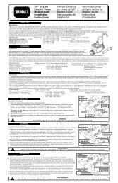
Testing ProceduresMODEL <strong>950</strong><strong>XL</strong> DOUBLE CHECK VALVE ASSEMBLY <strong>950</strong><strong>XL</strong> TEST NO. 2Equipment Required: Differential pressure gauge test kit.<strong>950</strong><strong>XL</strong> TEST NO. 1Purpose:Test #1 check valve for drip tightness against reverse flow.Requirement:The valve must close tight against reverse flow under all pressuredifferentials.Procedure:1. Close #2 and #1 shut-off valves.2. Open test cocks #2 and #3.3. Attach "VENT" hose to test cock #1, the "LOW" hose to test cock #2and the "HIGH" hose to test cock #3.4. Open by-pass valves "A" and "C", then open test cock #1.5. Open test cock #4 to bleed air from valve and test kit.6. Close by-pass valve "C". Slowly open by-pass valve "B" until differentialgauge reads 5 PSID. Close by-pass valve "B".7. The #1 check valve is considered tight if differential pressure ismaintained.MODEL <strong>975</strong><strong>XL</strong> REDUCED PRESSURE PRINCIPLEASSEMBLYEquipment Required: Differential pressure gauge test kit.<strong>975</strong><strong>XL</strong> TEST NO. 1Purpose:Test #2 check valve for tightness against reverse flow.Requirement:The valve must close tight against reverse flow under all pressure differentials.Procedure:1. Attach the "HIGH" hose to test cock #2 and the "LOW" hose to testcock #3.2. Close #2 shut-off valve.3. Open test cocks #2 and #3.4. Open by-pass valves "C" and "A" and bleed to atmosphere until allair is expelled.5. Close by-pass valve "A". Open by-pass valve "B" and bleed to atmosphereuntil all air is expelled. Close by-pass valves "B" and "C".6. Attach the "VENT" hose to test cock #4.7. Slowly open by-pass valves "A" and "C" and keep by-pass valve "B"closed.8. Open test cock #4.9. Indicated pressure differential will drop slightly. If pressure differentialdoes not continue to decrease, the #2 check valve is consideredtight.<strong>975</strong><strong>XL</strong> TEST NO. 2Purpose:Test #1 check valve for tightness and record pressure drop across #1check valve.Requirement:The static pressure drop across the #1 check valve should be at least3.0 PSID greater than the relief valve opening point (TEST NO. 3).Procedure:1. Close by-pass valve "A"2. Close test cock #4, and disconnect "VENT" hose from test cock #4.3. Open by-pass valves "B" and "C" bleeding to atmosphere, then closeby-pass valve "B" restoring the system to normal static condition.4. Observe the pressure differential gauge and note this as the #1check valve psid.2Purpose:Test #2 check valve for tightness against reverse flow.Requirement:The valve must close tight against reverse flow under all pressure differentials.Procedure:1. Close test cock #1.2. Attach "HIGH" hose to test cock #4 and "LOW" hose to test cock #3.3. Open by-pass valve "C". Open test cocks #1 and #4.4. Repeat step #6 of TEST NO. 1.5. The #2 check valve is considered tight if differential pressure ismaintained.#2 SHUT-OFFVALVE#4 TEST COCKHIGH SIDE HOSEBY-PASSVALVE "A"#3 TEST COCK#2 TEST COCKBY-PASSVALVE "C"BY-PASSVALVE "B"VENT HOSE#1 TEST COCK#1 SHUT-OFFVALVELOW SIDE HOSE<strong>975</strong><strong>XL</strong> TEST NO. 3Purpose:To test operation of the differential relief valve.Requirement:The pressure differential relief valve must operate to maintain the "ZONE"between the two check valves at least 2 PSID less than the supplypressure.Procedure:1. Close by-pass valve "C" and open by-pass valve "A".2. Open by-pass valve "B" very slowly until differential gauge needlestarts to drop. Hold the valve at this position and observe the gaugereading at the moment the first discharge is noted from the reliefvalve. Record this as the opening differential pressure of the reliefvalve.#2 SHUT-OFFVALVE#3 TEST COCK#4 TEST COCK#2 CHECK VALVEBY-PASSVALVE "A"HIGH SIDE HOSE#1 CHECK VALVE#2 TEST COCK#1 SHUT-OFFVALVEBY-PASSVALVE "C"BY-PASSVALVE "B"VENT HOSE#1 TEST COCKLOW SIDE HOSE
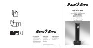
Maintenance InstructionsAll Model <strong>975</strong><strong>XL</strong> Reduced Pressure Principle and Model <strong>950</strong><strong>XL</strong> <strong>Double</strong>Check Valve Backflow Preventers must be inspected and maintainedby licensed personnel at least once a year or more frequently as specifiedby local codes. Replacement of worn or damaged parts must onlybe made with genuine "WILKINS" parts. The WILKINS Certificate ofLimited Warranty provides that failure to do so "...releases WILKINS ofany liability that it might otherwise have with respect to that device."Such failure could also result in an improperly functioning device.The Model <strong>975</strong><strong>XL</strong> Reduced Pressure Principle Assemblies should bethoroughly flushed after backflow conditions occur to prevent any typeof corrosive deterioration to its components. Failure to do so could resultin malfunction of the device.GENERAL MAINTENANCE1. Clean all parts thoroughly with water after disassembly.2. Carefully inspect rubber seal rings, diaphragms and o-rings fordamage.3. Test unit after reassembly for proper operation(see "TestingProcedures").SERVICING CHECK VALVES1. Close inlet and outlet shut-off valves.2. Open No. 2, No. 3 and No. 4 test cocks to release pressure fromvalve.3. Unscrew check valve covers using appropriate size wrench (CAU-TION: Cover is spring loaded). To avoid injury, hold cover down firmlywith one hand while unscrewing.4. Remove check valve cover, spring and poppet assembly.5. Inspect the rubber seal ring for cuts or embedded debris. To removeseal ring, remove screw and seal ring retainer. If the reverse side ofthe seal ring is unused, it is possible to invert the seal ring. Thiswould be considered a temporary solution to fixing a fouled checkand should be replaced with a new seal ring as soon as possible.6. Inspect valve cavity and seating area. Remove any debris.7. If installed with removable seat, unscrew seat from body and replacewith new seat and lightly grease o-ring.*8. Reverse the above procedures to reinstall check valve assembly.Care should be taken to make sure the heavy spring is installed inthe No. 1 check valve (Model <strong>975</strong>'s series only). For the 3/4"-1"<strong>975</strong><strong>XL</strong>SE the No. 2 poppet has a cupped seal retainer. For the1 1/4"-2" <strong>975</strong><strong>XL</strong>SE the No. 1 seat has a taller seat profile than theNo. 2 seat.SERVICING RELIEF VALVE1. Remove relief valve cover bolts and cover. Gently pull on diaphragmto remove the cartridge assembly.2. Inspect seal ring for cuts and embedded debris. Turn over or replaceif required.3. Disassemble cartridge by unscrewing relief valve retaining screw.4. Inspect diaphragm and o-rings for damage. Replace required partsand apply a light coat of grease to plunger o-ring.5. Carefully reassemble cartridge assembly.6. Inspect relief valve seat for wear on seating surface. If damaged,replace seat and seat o-ring.*7. Insert cartridge assembly into relief valve body.8. Replace relief valve cover and cover bolts.9. Place device in service and test per "TESTING PROCEDURES".*For seat removal assistance, consult factory.RETAINING SCREW(CHECK)SEAT(CHECK)SEAL RING RETAINERCOVER(CHECK)(CHECK)SPRING(CHECK)RELIEF VALVE COVERCOVER BOLTSDIAPHRAGMSEAT(RELIEF VALVE)SPRING(RELIEF VALVE)SEAL RING(RELIEF VALVE)POPPETO-RING(CHECKSEAT)SEAL RINGO-RING(COVER)(CHECK)TroubleshootingWhen the relief valve discharges intermittently it can be almost always assumed that the device is functioning correctly and that the discharge iscaused by systems such as inlet pressure fluctuations or water hammer due to quick closing valves.PROBLEM1. SUDDEN OR RAPID SPITTINGPOSSIBLE CAUSES1. Drop in inlet pressure.2. Sudden increase in downstream pressuredue to waterhamnmer from quick closingshut-off valve installed downstream.CORRECTIVE ACTIONA. Install an in-line spring loaded check valveupstream of backflow.B. Install pressure reducing valve upstream ofbackflow unit.C. Install in-line spring loaded check valvedownstream of backflow as close to sourceas possible, but not closer that 4 feet.2. LIGHT INTERMITTENT DRIP 1. Slightly fouled #1 check. A. Clean #1 check and turn check valve sealring over or replace.Continuous discharge of the relief valve signifies a failure of some part of the device. To help determine the specific area of failure, close the #2 shutoffvalve. If the discharge stops, the #2 check requires service. If the discharge continues, the #1 check requires service.1. CONTINUOUS DISCHARGE 1. Fouled #1 check.2. Fouled relief valve seat.3. Fouled #2 check.O-RING(PLUNGER)PLUNGER(UPPER)PLUNGER(LOWER)SEAL RING RETAINER(RELIEF VALVE)RETAINING SCREW(RELIEF VALVE)SEAT O-RING(RELIEF VALVE)A. Clean check valves and turn check valveseal rings over or replace.B. Clean relief valve seat and turn relief valveseal ring over or replace.In summation, the amount of discharge is proportional to degree of fouling. Most problems occur in the #1 check which is where debris enters thebackflow preventer first.3
Performance CharacteristicsPRESSURE LOSS (PSIG)MODEL <strong>975</strong><strong>XL</strong> 1/4", 3/8" & 1/2" (STANDARD & METRIC)FLOW RATES (l/s)2015100.19 0.38 0.57 0.761/4" (6mm)3/8" (9mm)1/2" (15mm)3550 3 6 9 12 15FLOW RATES (GPM)Rated Flow (Established by approval agencies)0.9513710369PRESSURE LOSS (kpa)Capacity <strong>thru</strong> Schedule 40 PipePipe size 5 ft/sec 7.5 ft/sec 10 ft/sec 15 ft/sec1/8" 1 1 2 31/4" 2 2 3 53/8" 3 4 6 91/2" 5 7 9 143/4" 8 12 17 251" 13 20 27 401 1/4" 23 35 47 701 1/2" 32 48 63 952" 52 78 45 167SPECIFICATIONSMaximum working water pressure 175 PSIMaximum working water temperature 180°FHydrostatic test pressure350 PSIEnd connectionsThreaded NPTANSI B1.20.1PRESSURE LOSS (PSIG)15105MODEL <strong>950</strong><strong>XL</strong> 3/4", 1", 1 1/4", 1 1/2" & 2" (STANDARD & METRIC)FLOW RATES (l/s)1.26 2.52 3.8 5.03.2 6.3 9.5 12.6153/4" (20mm) 1" (25mm) 1 1/4" (32mm) 1 1/2" (40mm)00 20 40 60 80105FLOW RATES (GPM)Rated Flow (Established by approval agencies)2" (50mm)15.810300 50 100 150 200 2506935PRESSURE LOSS (kpa)PRESSURE LOSS (PSIG)2015101.26MODEL <strong>975</strong><strong>XL</strong> 3/4", 1", 1 1/4", 1 1/2" & 2" (STANDARD & METRIC)2.523.8FLOW RATES (l/s)3/4" (20mm) 1" (25mm) 1 1/4" (32mm)5.035550 20 40 60 80 0 50 100 150 200 250FLOW RATES (GPM)2015103.2Rated Flow (Established by approval agencies)6.39.51½"(40mm)12.62" (50mm)15.813710369PRESSURE LOSS (kpa)Proper performance is dependent upon licensed, qualified personnel performing regular, periodic testing according to WILKINS' specificationsand prevailing governmental & industry standards and codes and upon following these installation instructions. Failure to do so releasesWILKINS of any liability that it might otherwise have with respect to that device. Such failure could also result in an improperly functioningdevice.ISSM<strong>950</strong> (REV. 8/03)WILKINS OPERATION OF ZURN PLUMBING PRODUCTS1747 Commerce Way, Paso Robles, CA 93446 Phone:805/238-7100 Fax:805/238-5766acompany